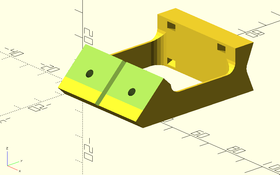
I was thinking of making the dovetail joint wedge shaped where the edges are not parallel, but converge towards the bottom. This way, even if the clamp lets go entirely, the piece cannot fall out, and if there is some discrepancy in suze for.smaller errors like extrusion, it will still fit.
You can make the dovetail groove a bit deeper, because the wedge will force consistency.
I’m away from all of my CAD right now or I’d draw up wn example of what I’m talking about
@SupraGuy
I’m a bit sleepy/drowsy today, and it’s making me dull. If you get a chance later to do a napkin sketch that would be awesome. I’m not grasping it as of yet. It sounds like it could be a great idea.
I think I get it, “it can not fall out”, by example if a laser is attached.
But it can be pushed up now?
By example if you attach a pen, it gets “pushed up” because of the force from below, which can lead to a wiggly result (if the latch does not hold it tight)?
@DougJoseph as far as I can see, he has “inverted” the “tongue and groove”. The Mount does have the tongue now and the attachment has now the groove. Before it was basically the opposite.
I hope I get it right and doesn’t bring in more confusion
Thanks. The potential problem whenever the cam lever does not hold, is a problem no matter which way the wedge is tapered. Tapered one way, the cam keeps the tool from falling. Tapered the other way, it keeps the tool from being pushed out of the mount by upward force from the material (pen and drag knife, for example).
Gravity is a relatively weak force. My logic in turning the taper of the wedge the way I did, was because the potential for upward force from the machine pressing against the material, seemed to me to be potentially greater than the force of gravity.
To add to the previous comment, of the two provided ways to constrain the tool from unwanted movement, one, the friction block of the tool holder pressing against the mount base, and, the other, the friction block of the cam lever, the tool holder against the tapered wedge is the stronger, more dependable. That’s why I targeted it on preventing upward force from dislodging the tool, and the less trustworthy, on keeping gravity from causing a fall.
Update: so, @jamiek 's mention of the word “kinematic” sent me down that rabbit hole. I found numerous successful creations of kinematic tool changer mount systems, including this one that’s amazingly fast on the changes and seems very solid: Cable-Driven Tool Changer System by poofjunior - Thingiverse
Here’s a video of the above one in action:
Also, this other one seems more economical in its design, and has also been proven in real world use:
… However I don’t see a link to design files or printable models. I’ve begun some dialogue with that maker in the comments of his video, and I’ve asked if he has shared them or would be willing to.
In the meantime, I can use the same principles and examples to design something similar. While we would all like to avoid buying hardware and just go with printed plastic where possible, this seems like an instance where the hardware could be warranted, depending on your need for repeatability between changes of tool/accessory.
Just wanted to give a clue to what’s happening in my brain while this project is on a bit of a hold.
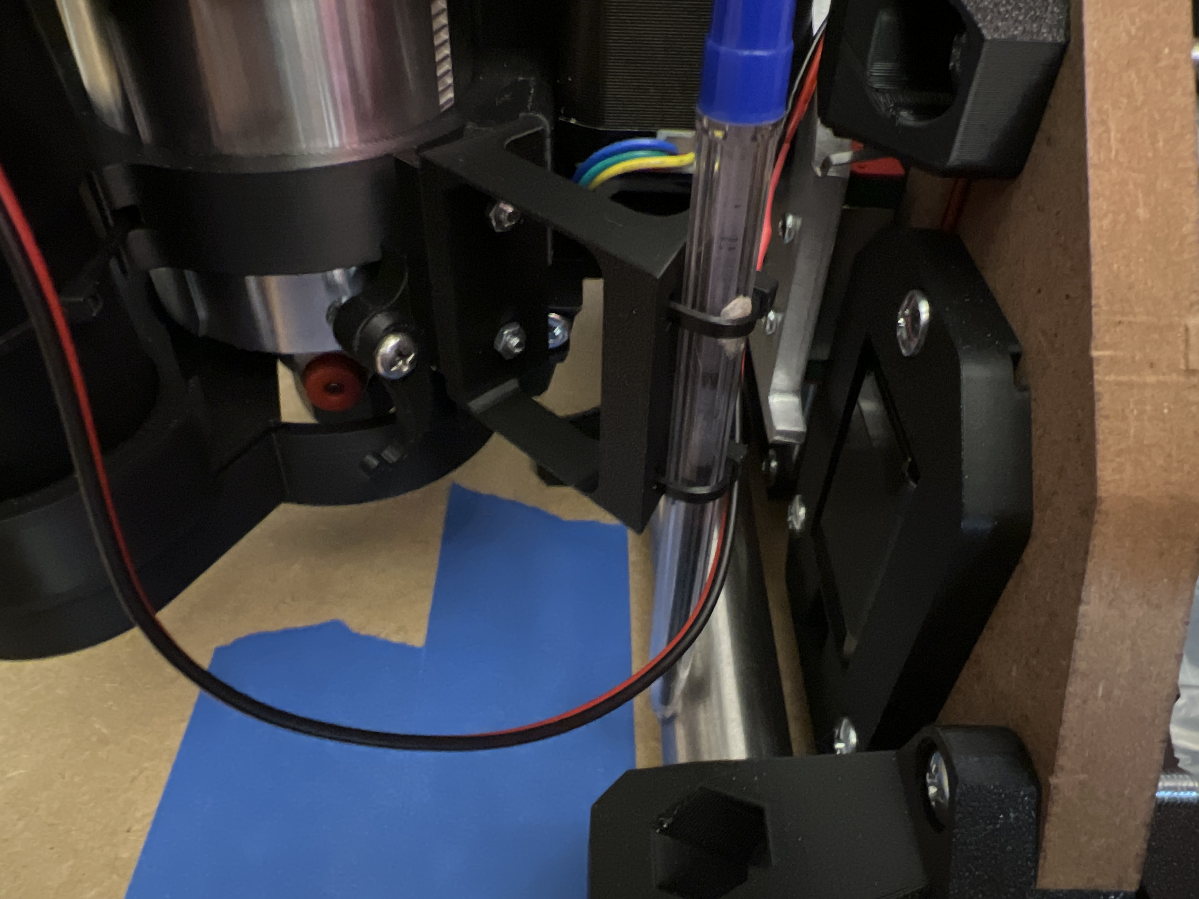
The docs exercise you’re referencing assumes use of a pen with no “springiness feature” by virtue of being attached either by lashing it directly to the router, or using it in place of the router. The offset length of this design is intended to provide springiness, and yet also allow semi-permanence, leaving added tool on without having to replace the router. This design’s thin “spring leafs” feature has to walk a tight rope to balance between having enough strength not to break, and yet having enough bend to achieve springiness. The length of the leafs was initially set by whoever came up with this approach. (This is now quite a few iterations down the road from the original.) One could certainly shorten the leafs, but doing so would defeat the purpose of it having springiness. This means any use of the pen or drag knife etc, needs to account for the offset.
Second point is this: there are other ways to achieve springiness, including— you guessed it— use of actual metal springs. There is s trade off in using printed plastic as the spring. I recently released a video showing a way to modify a ballpoint pen to add a spring from another pen, to give the pen built-in springiness.
Assuming one’s table surface is flat enough, one can go without any springiness. But the real world table is often not flat, and the bigger the table the more the need of springiness.
Also note, there are other pen mounts that don’t worry about providing springiness, and that decision gets the add-on tool closer to to core’s center (less offset).
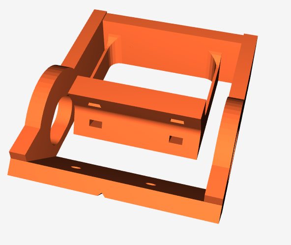
Finally, this remix itself is being overhauled majorly to achieve a kinetic style of attachment which should give much, much better repeatability on positioning during tool switching. I’ve got the prior version on hold since I’m overhauling it.
Thank you for that explanation, like suggested I used x-10mm as an offset to use the squareness code generator.
Another solution would be to to change the angle for the mount or pen attachment.
Its really not much, with that change the whole length of the x axis could be used.
Thank you for your work, I’m looking forward to your new version
This would be a valid approach. My original logic in the orientation was to have an equal number for both X offset and Y offset (45 degree offset). If the angle was turned so that the offset was all in one axis, Y, with zero X offset, it would provide full range on X axis, but would increase the deficit to usability in the Y axis.
At RMRRF I heard Ryan describe to someone the design process for this pen holder. Suffice to say the design embodies some optimization as far as stiffness and printability, so casual changes to the flexure are likely to make it somewhat worse.
Having said that, maybe there could be an inverted version where a rigid arm sticks out a few inches and the flexure is pointed back toward the router (or whichever mounting point). Then you could have the same function with the pen a bit closer to the router. If that matters.