Yep, makes sense. 5.2 and 5.3 are probably found in various sources, depending on whatever. I’m OK with either. I have them set to 5.2 now.
1 Like
OK, I have the overhauled the version on Printables, now set to version 3.1. I have not yet done a test print of the new revision, but will be re-printing directly. In the meantime I’m going ahead and letting it be shown on Printables because, since you have such a capable printer, both quick and well calibrated, I’m hoping you can also do a test print and report back. Please note that although many key areas of fitment have been revised, I have not yet revised the location of the pivot hole on the cam lever, until we can do some printing of the new revision and see how it “clamps” or does not. This new version deliberately has no upper stop block, so the tool accessory can just slide until the wedge shaped track engages. This should grant leeway for printers that either under extrude or over extrude.
https://www.printables.com/model/420517-lowrider-v3-cnc-tool-less-quick-change-accessory-h
2 Likes
Cura slicer says I can have a working set in 1 hour and 18 minutes, but I usually run faster by increasing speed and flow, so I estimate I’m about an hour out from a test set.
This is for printing one each of Mount A, B, and C.
1 Like
Amazing, great idea Doug!
I’ve started a print of every file now.
After this night I will let you know everything I’ve noticed ![]()
1 Like
Hey, on the newly revised listing, I had tried a much tighter fit on the Mount Part B. However, it was way too tight on my end (my printer may be over extruding). So I added one that was the same fitment as the previous version, and I left the super tight one too. I updated the print notes to say the following:
- I’m including two versions of Accessory Holder v3.1 MOUNT B - a “NORMAL FIT” version and a “VERY TIGHT FIT” version. I recommend trying the normal first. If your printer is under extruding then you could switch to the “very tight fit” version. Otherwise, the tight version is not likely to work for you at all.
2 Likes
will try to find some time this evening to print it out & test it.
1 Like
Observations:
-
M5 Screw holes did not get modified to 5.2mm in “Accessory Holder v3.1 MOUNT A.stl” (Both holes have still different sizes)

-
The “Accessory Holder v3.1 MOUNT B - VERY TIGHT FIT.stl” (Which I guess was the first version I’ve printed after writing you) is too tight:
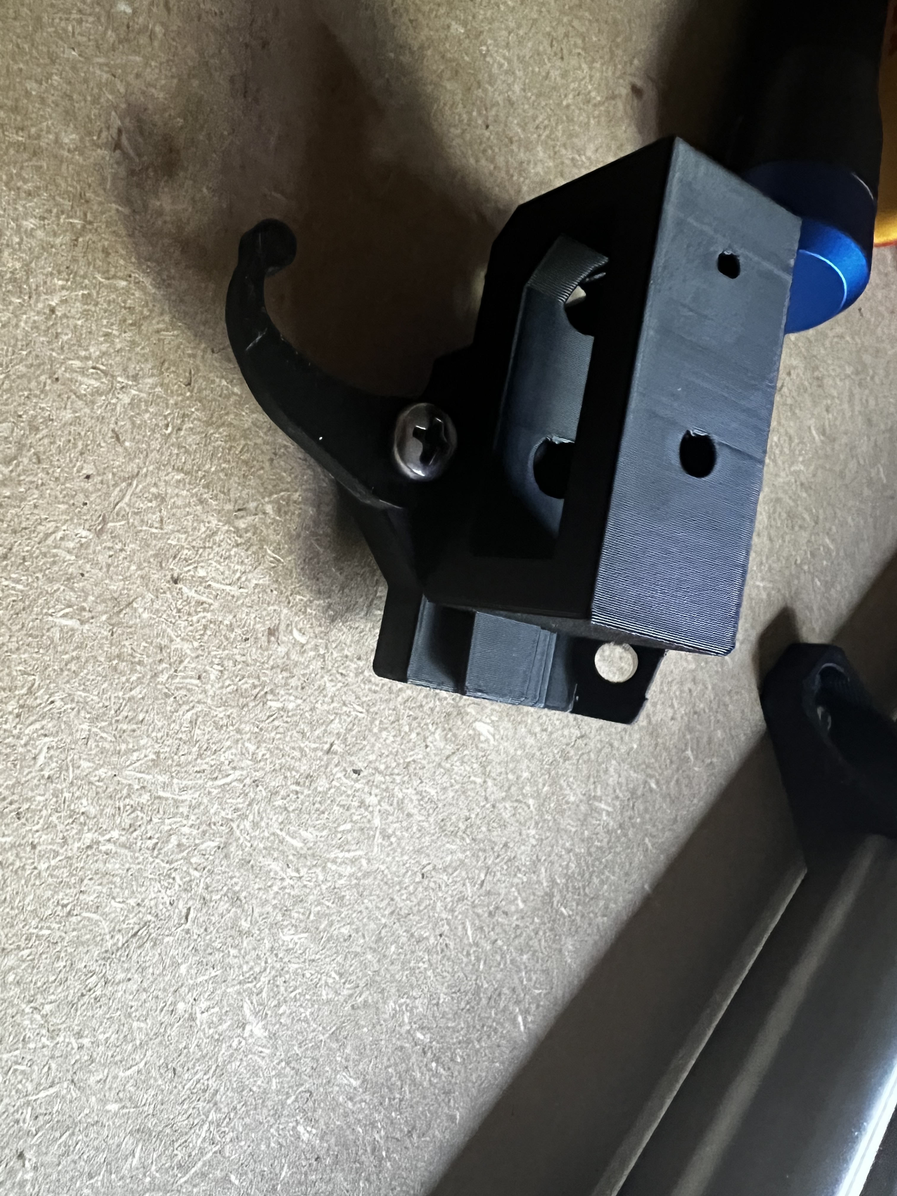
- The “NEJE A40640 Laser mount v3.1.stl” is the opposite, its very loose, which results in sliding it up very much, but that’s the hole point of the mechanism, right? Either way a little bit tighter would be great

- If I attach it like this, its rock solid, the latch does really “push” into the attachment like it should:
My take aways:
-
Thank you for the fast update!
-
Please resize the different sized M5 screw holes we’ve talked about
-
What would be great: If you could find a “middle ground” between the “tight fit” version and the “Laser attachment”? One is too tight the other is too loose. Would be great to find an “average” of both
P.S.:
I’m printing your new “normal fit” version of accessory holder B now, will update you once I’ve tried it.
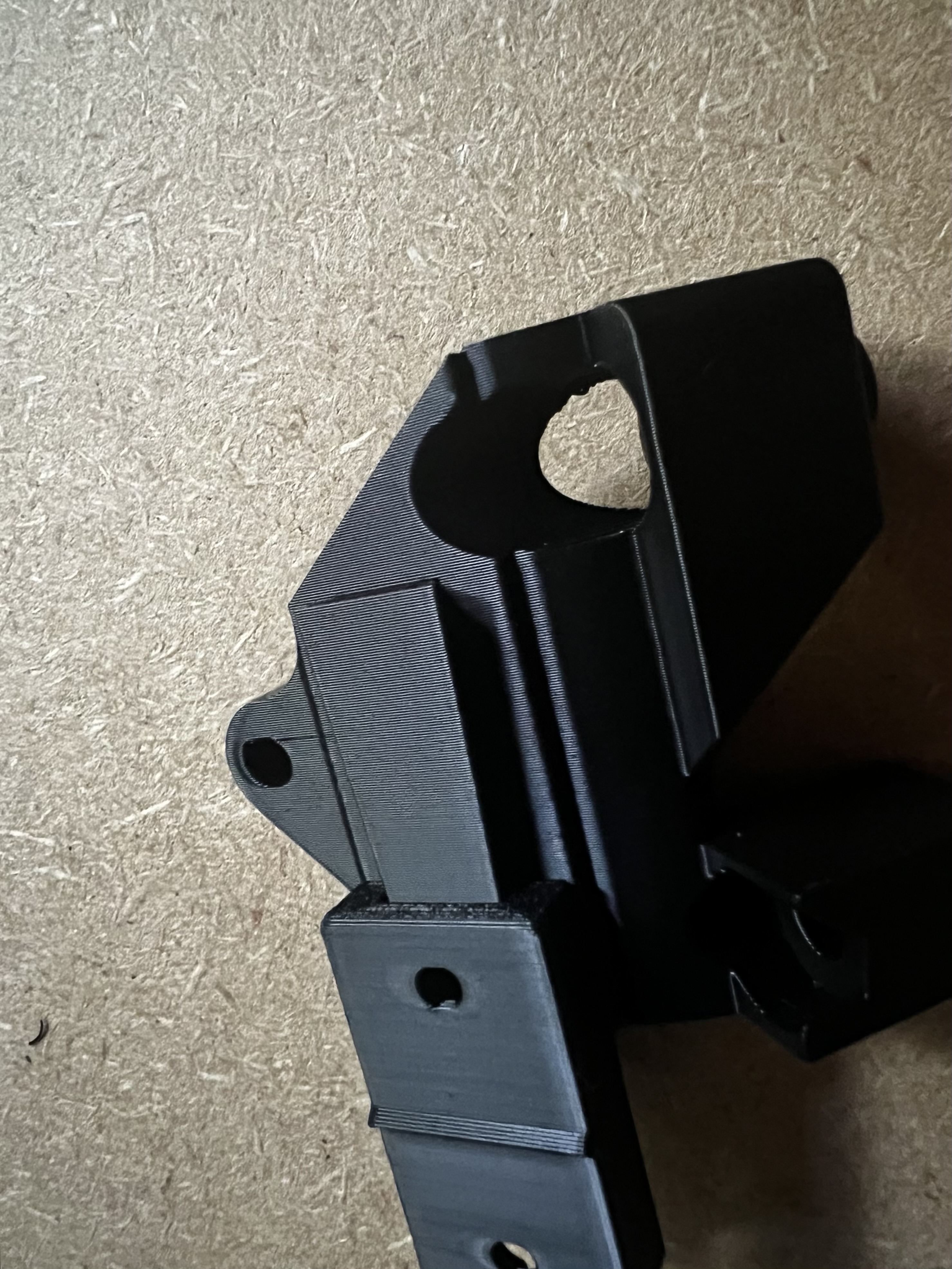
The „normal fit“ is the loosest of all:
Compared to the laser attachment:
And compared to the tight fit which does not fit at all:
Summary:
„Tight fit“ = too tight
Laser attachment = a little bit loose
„Normal fit“ = the loosest
For clarification:
With loose I mean it can be pushed up relatively high. Both are holding strong at the high position.
Would be great if you could find a „middle ground“ between the laser attachment & tight fit.
Or at least make the „normal fit“ as tight as the „laser attachment“.
Because I understand that you want to give it a margin for different printers, but at the moment the „normal fit“ is really loose, it’s about 45% „outside“ of the holder it’s attached to.
Anyway it’s useable now, which it wasn’t before ![]()
1 Like
I most definitely edited the M5 screw holes — will double check.
Will create a new normal with the current normal being described as loose.
Re. the difference between the laser module, and the part I described as normal fit: the wedge opening is (I think) the same on them, but the laser module is meant to mount with its bottom lower than the regular mount. This is because someone explained that the laser mount needed to be further down. So that’s why there’s a difference. So, even though you’re describing them as being different between each other, they’re actually the same amount of opening in the wedge.
Thank you for all the great feedback!
1 Like
Well, I just found that I uploaded the old model instead of the new one, for “Accessory Holder v3.1 MOUNT A.stl” — which explains why my edits to the screw holes did not make it online. Fixing it.
1 Like
I think a good goal would be a kinematic mount that is inherently repeatable and insensitive to print variations, rather than tuning to the print quality.
If you had pens in multiple colors and wanted to pause within the job to switch colors, you would want the Z to be very consistent between pen holders and between installations.
Or maybe a removable probe with a known offset from the router bit.
I apologize for sounding like a downer but I think there is some really cool unrealized potential here that can make this even better.
3 Likes
@jamiek
I totally agree. One issue with that kind of repeatability is that the printer that printed the mounts may have not quite had the repeatability to begin with, and another is that because of those long “spring leaf” extensions on several of the tool holders (pen, drag knife) any slight variation gets magnified, so that even if the Z lines up, the X,Y registration is off.
My issue is not that I don’t see the value in what you’re saying, but that my tired brain is not creative enough to figure out a better solution.
I’m thinking now of a different approach. Instead of the wedge, have a mount that is only concerned with the fit between the cam lever and the one near side of the base, and being pressed against a top “end stop” surface.
Also, along the way, I’ve become aware that although I had calibrated e-steps on my various printers quite a while back, somehow something has changed that has them off. One of my main printers I use a lot is over extruding by a serious amount. I’m working now to calibrate again!
UPDATE:
OK, so the printer I thought was over extruding appears to actually be under extruding, however, I typically print with manually telling the printer to increase both its speed and its flow (typically 120% on both) so that may be what switches it from under extruding to over extruding. I’m working on it.
1 Like
I know it is a redesign at thos point, but have you considered a wedge shape for the dovetail joint? Even a 5° taper would allow for quite a bit of tolerance for different printers
@SupraGuy
Are you meaning running a wedge with increasing distance away from the flat of the main base? I think I may be following you, but I’m not certain.
Fyi
Just printed the normal fit, is as loose as the original one. Running out of PLA so nit sure when I can test print the tight fit.
@Olivier
The tight fit is not something to bother with testing. It would be for someone whose printer is under extruding, and they are more interested in getting a part than in fixing their printer. ![]()
At this time, I’m in a phase of rethinking this, and basically on hold until I can get more clear on it.
1 Like
Just wanted to say the even your tired brain is doing great things. Thanks for doing this!
2 Likes