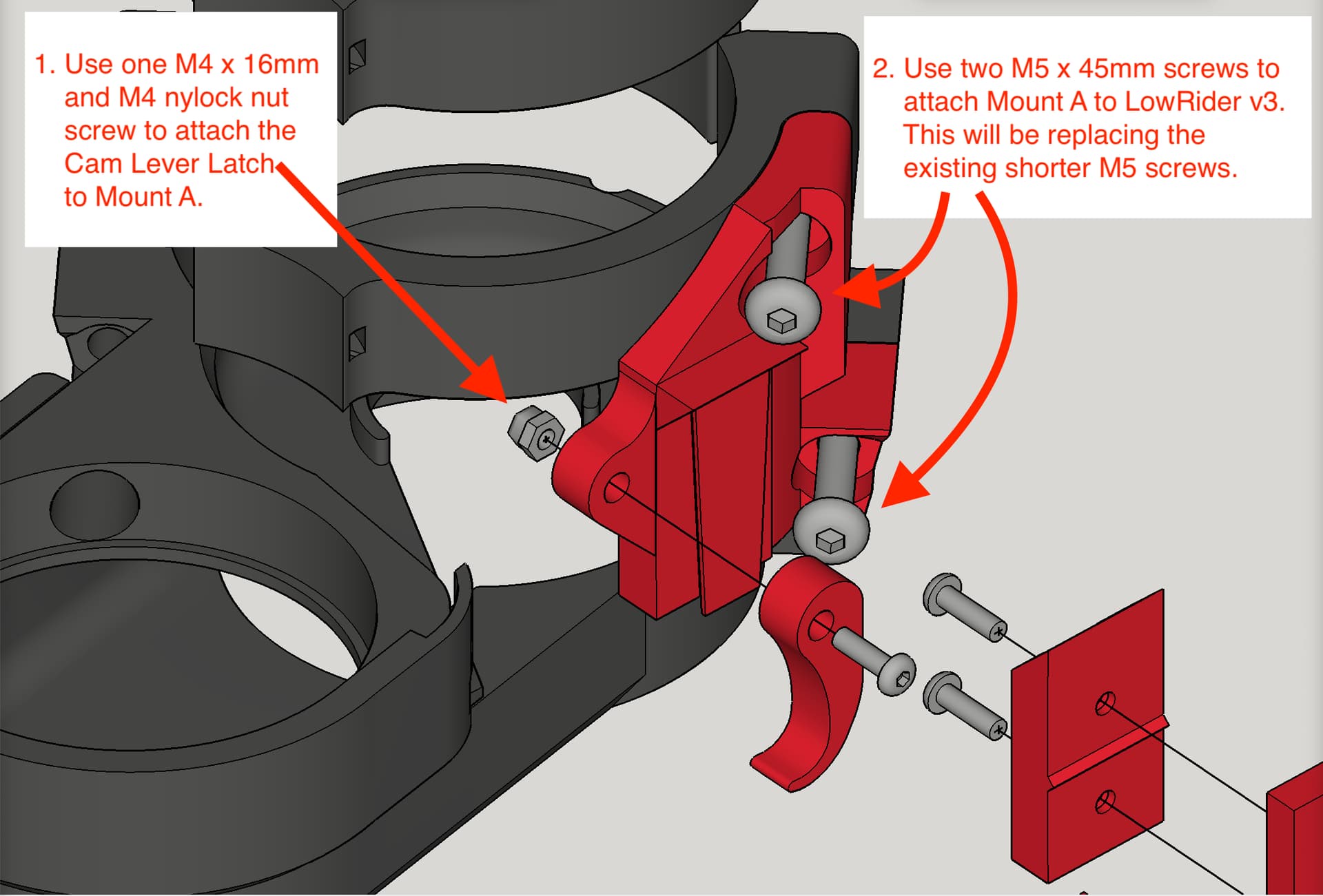
For understanding of how it works and assembly steps, just watch the 1-minute video.
This is a remix of several prior iterations.
Print info:
Prints with no supports needed.
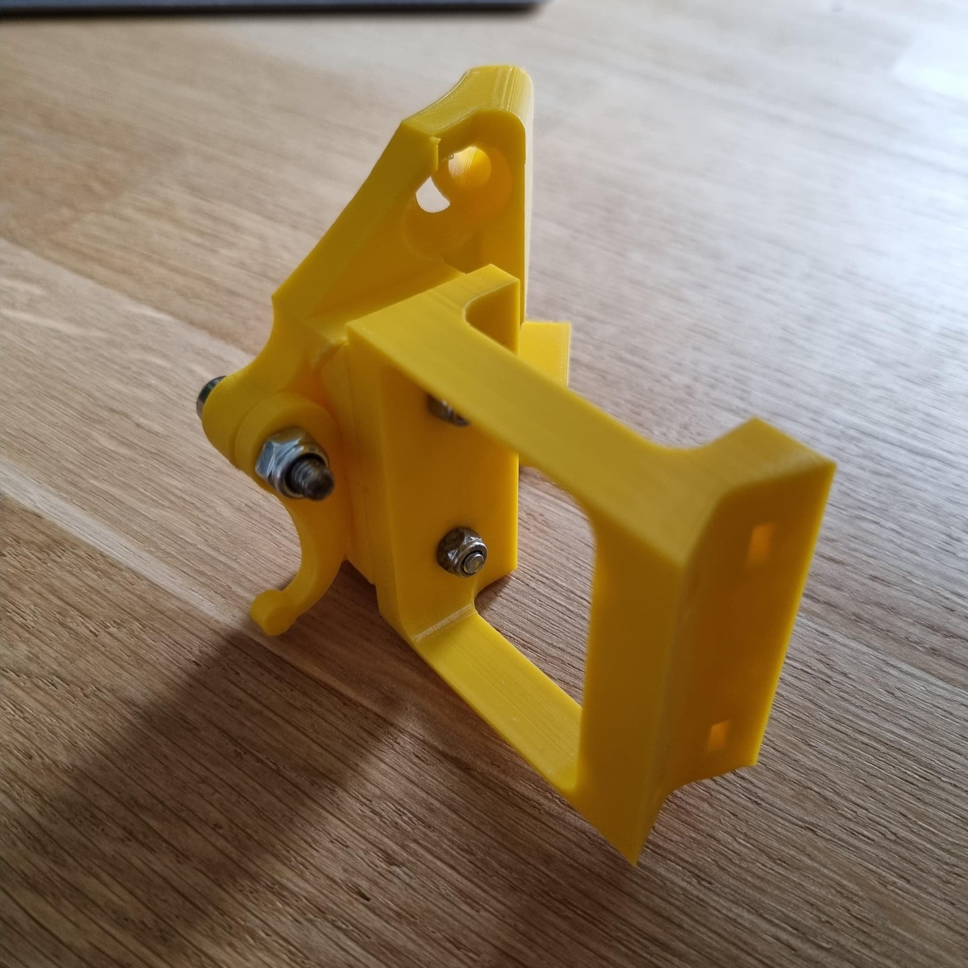
Print as oriented.
Use the same number of perimeter walls and same infill as most of the LowRider 3 parts.
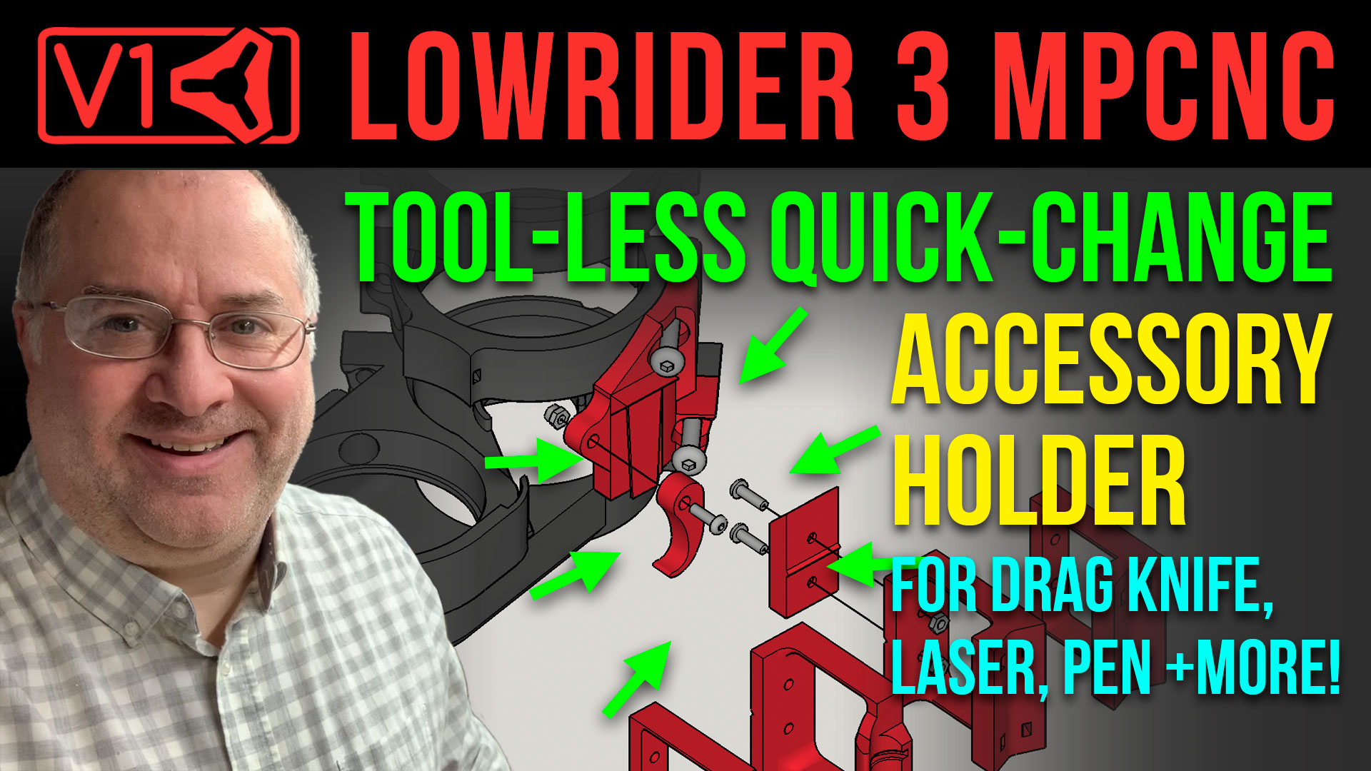
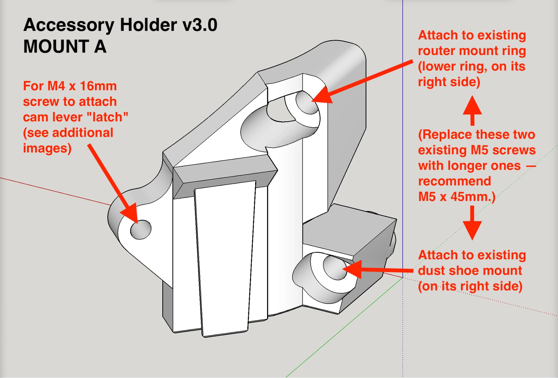
This design can work with either the original LR3 router mount & dust shoe (for 48mm hose) designed for Makita router, and also can work with my remix of that mount & dust shoe (for 2.5" hose), which is linked below. Other router mounts (such as Dewalt) may also be supported if they were based on the same design from V1 Engineering.
Change log:
March 10, 2023 - Original remix uploaded. Labelled as v3.0.
Now includes a NEJE A40640 Laser mount, thanks to help from Brady B’s remix of my earlier work.
To the 12 people who downloaded this between its launch and today’s fix of the one part labelled “Accessory Holder v3.0 MOUNT B (Tool Change Slider).stl”: please re-download and if you already printed that part, please reprint it.
In mid-stream on designing this, I realized by making a switch to screw hole locations, I could achieve backwards compatibility with earlier versions of the pen holder. In making those changes, I failed to edit the “Accessory Holder v3.0 MOUNT B (Tool Change Slider).stl” before publishing the design on Printables. That’s the reason it had to be fixed today.
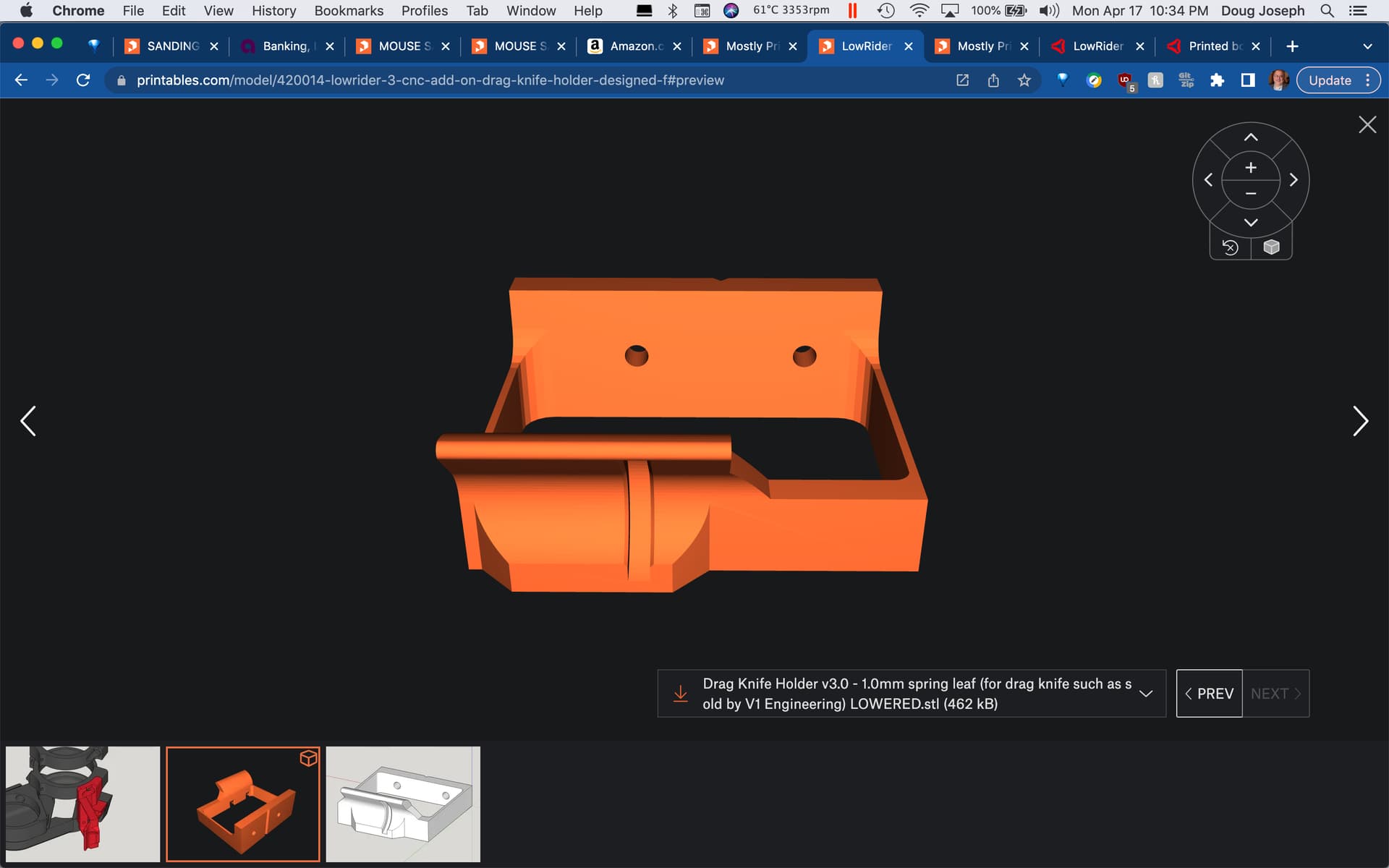
I just posted a revised, lowered version of the drag knife holder.
Both here: Printables
…and here: Printables
I added the following to the CHANGE LOG:
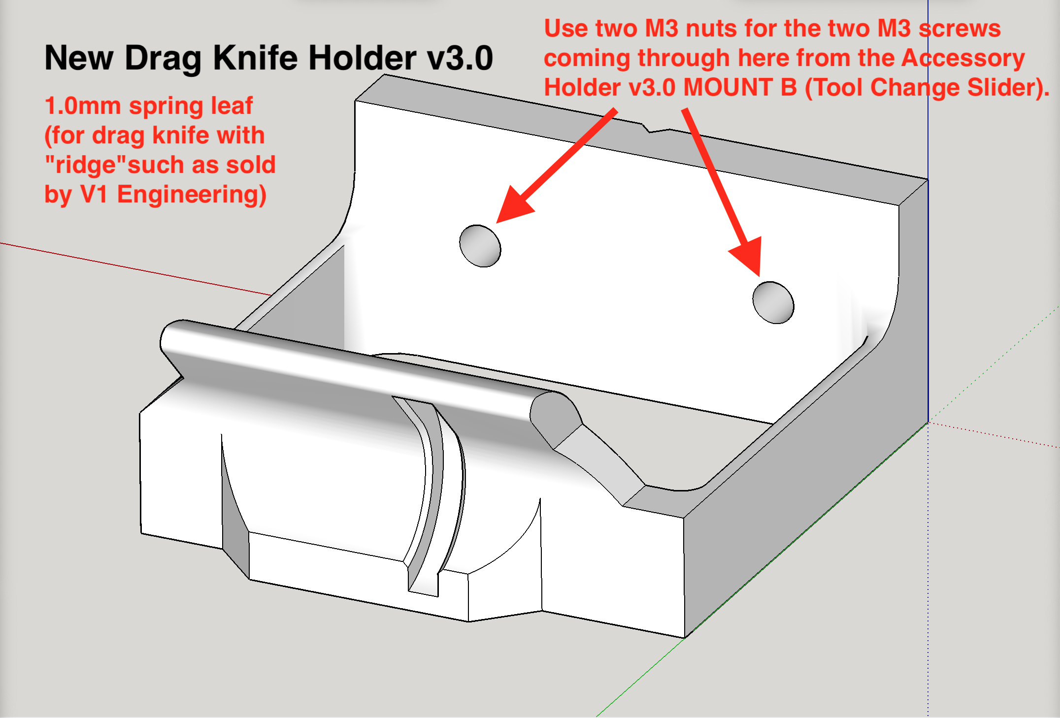
April 17, 2023 - revised the drag knife attachment to lower it, as fellow V1E maker Tom @Tna_331, reported the height of drag knife was too high, needing lowered by at least ½" —this revised version was lowered by 17mm.
My pen wouldn´t stay in place during the squareness test so figured (after updating the script to use dots instead of brackets) it is time to print one of your marveles designs. So thanks for that!
I have some feedback on the parts, to make it even better.
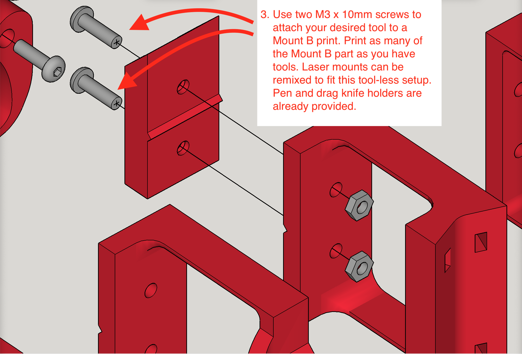
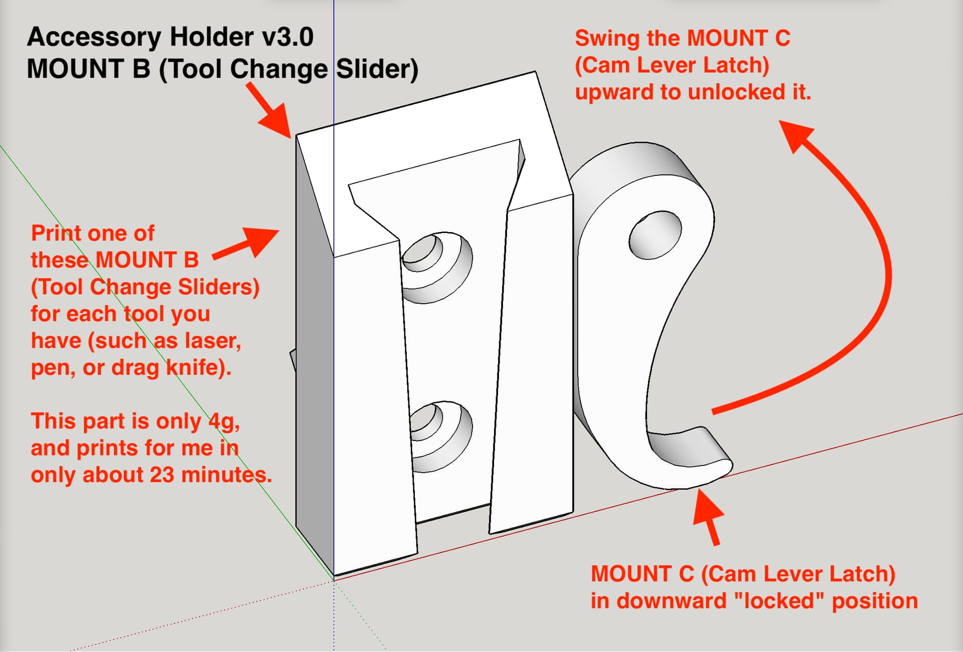
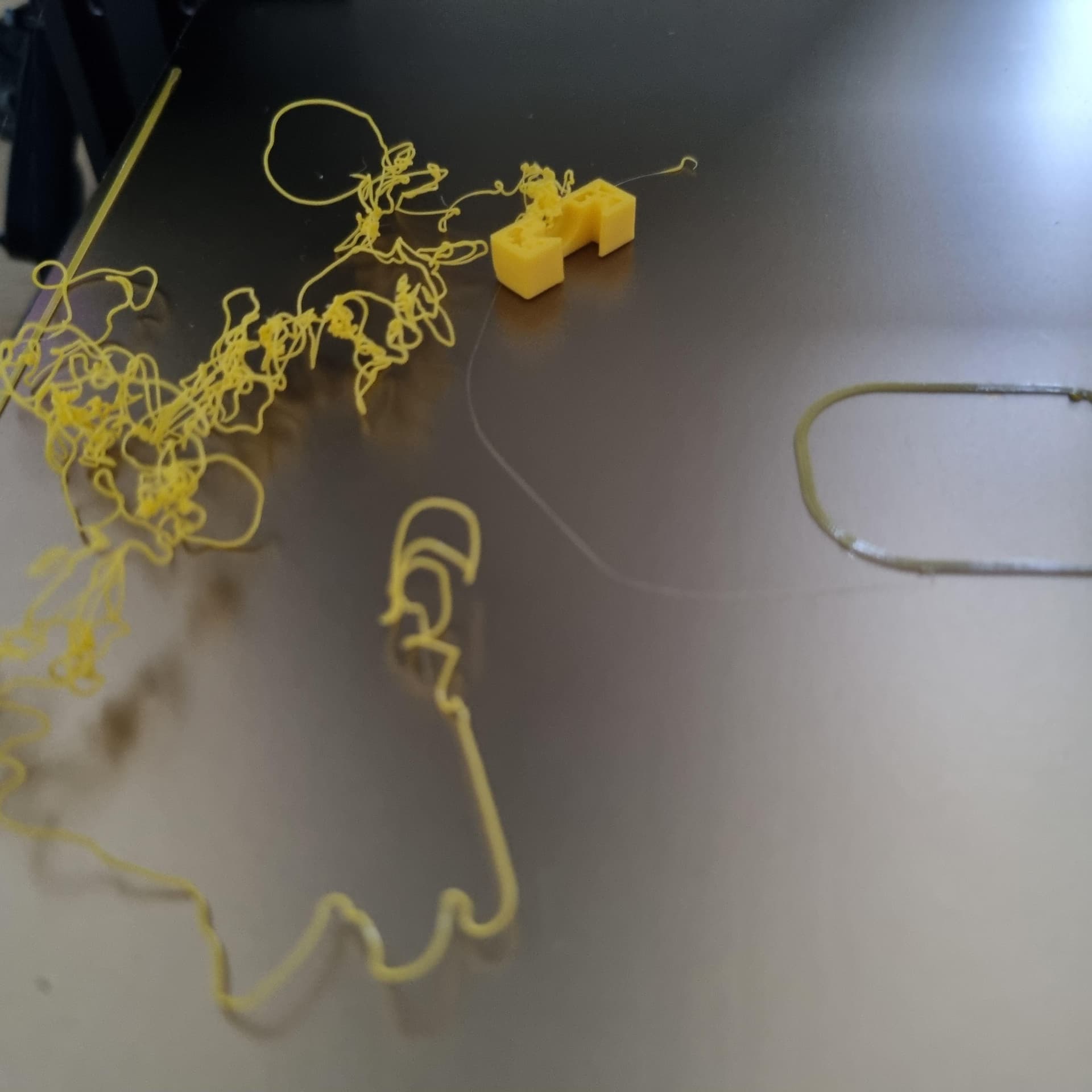
I had to print “Mount B” like 5 times before the print was a succes. I even retuned my Ender 3V2 before I succeded. It was strange :s So would add in your notes to print at least with a skirt.
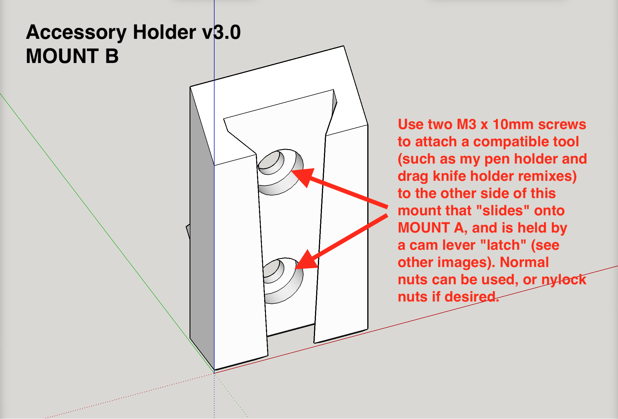
I also wonder why you made it a separate part instead of merging it with the tool mounts?
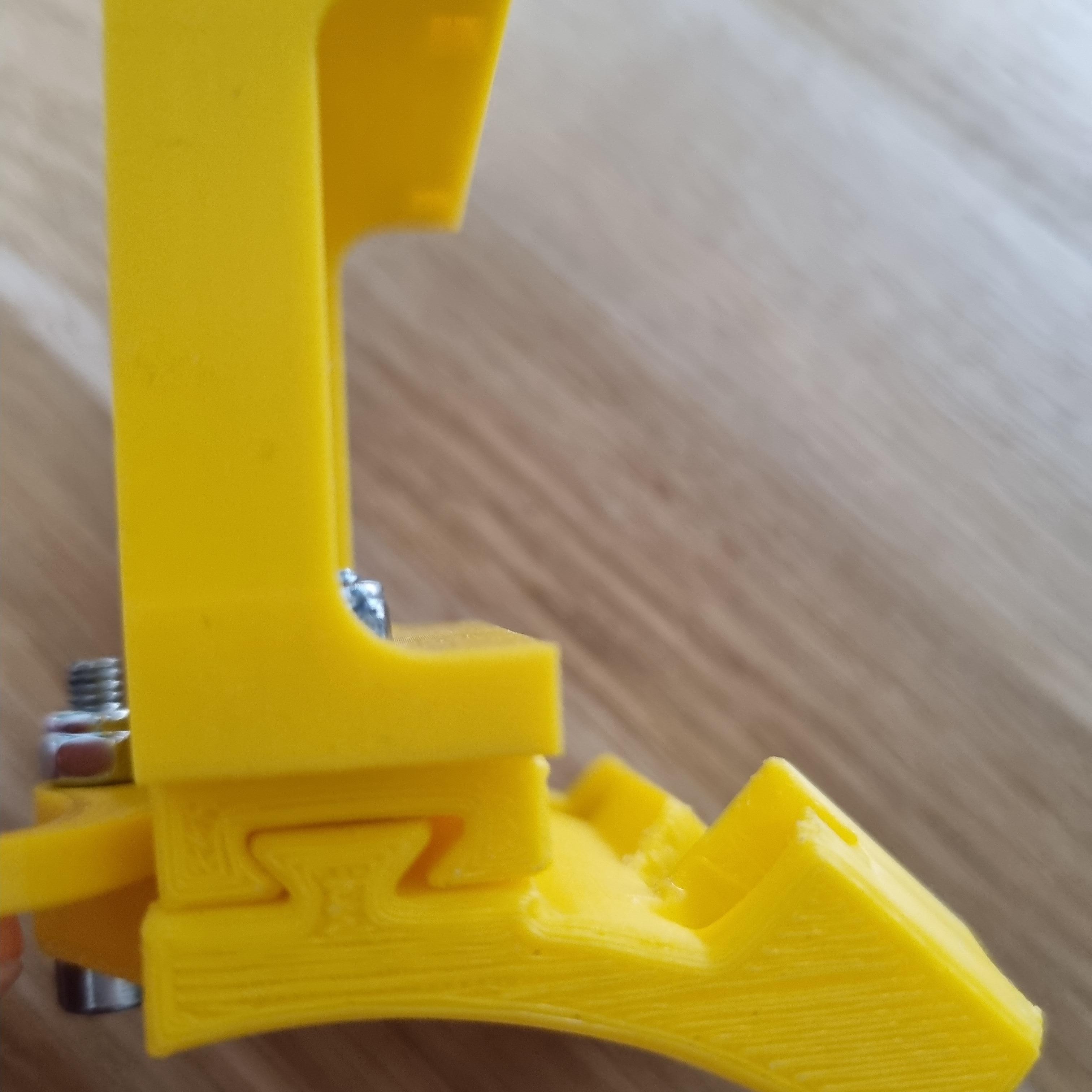
But even with the latch closed as it should I notice the tool mount drops out easily.
So would recommend the following:
make mount B a tighter fit on the clamping part, there is too much play (although I understand why you designed it this way)
Thank you for the great feedback, and the helpful suggestions. Below are some thoughts in response.
You mentioned retuning, and I’m wondering if you calibrated your E steps? The reason why I ask is because if a printers E-step‘s are not calibrated, then you can wind up with either over extrusion or under extrusion. This design is more sensitive to under extrusion than some other designs.
Regarding getting good adhesion on your part to the printer bed, I find it very helpful to put a light coating of hairspray on the print bed every so often before I print, and enabling a brim is also a helpful way to increase the adhesion to the board, and the brim is not hard to cut off later after succeeding with the print.
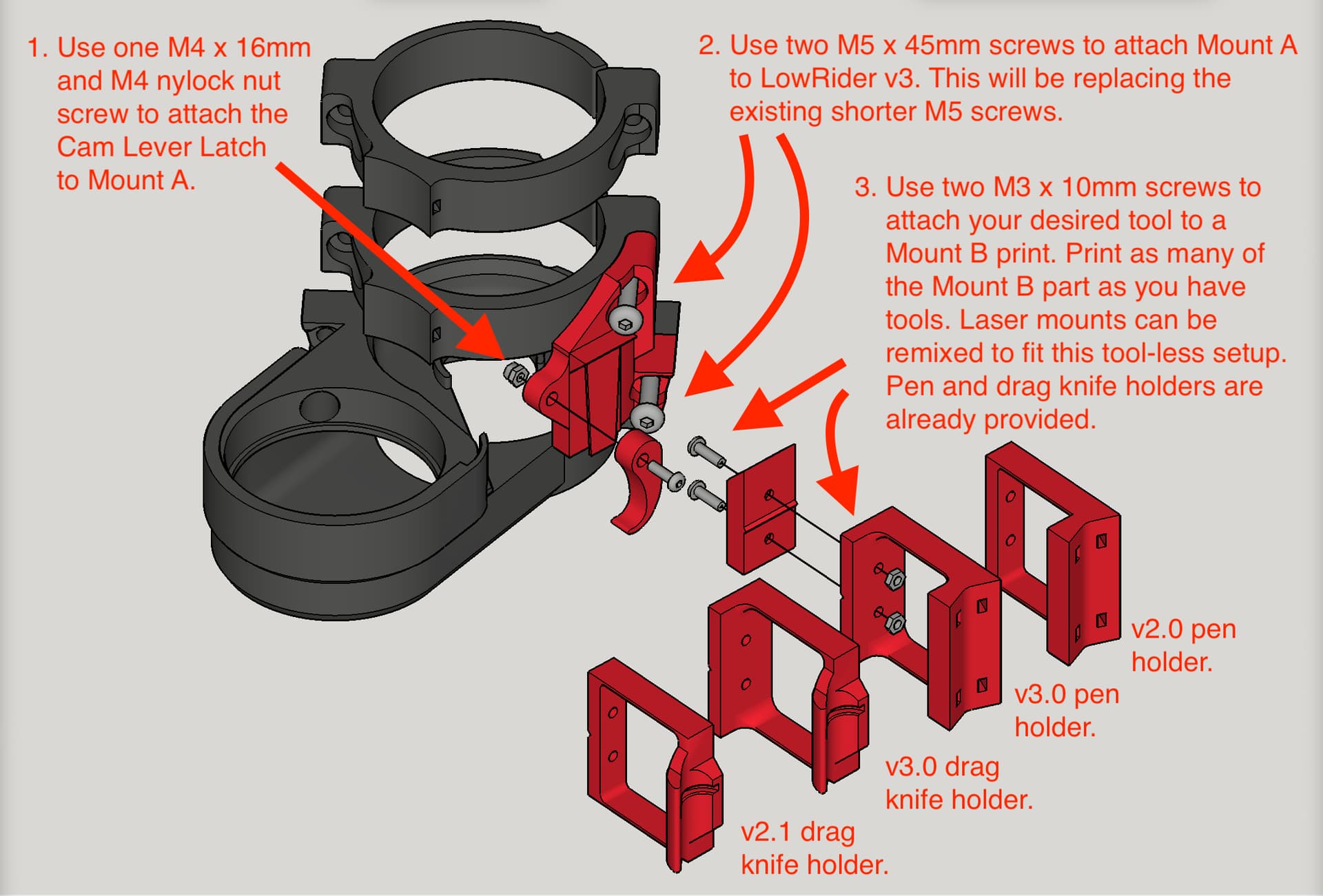
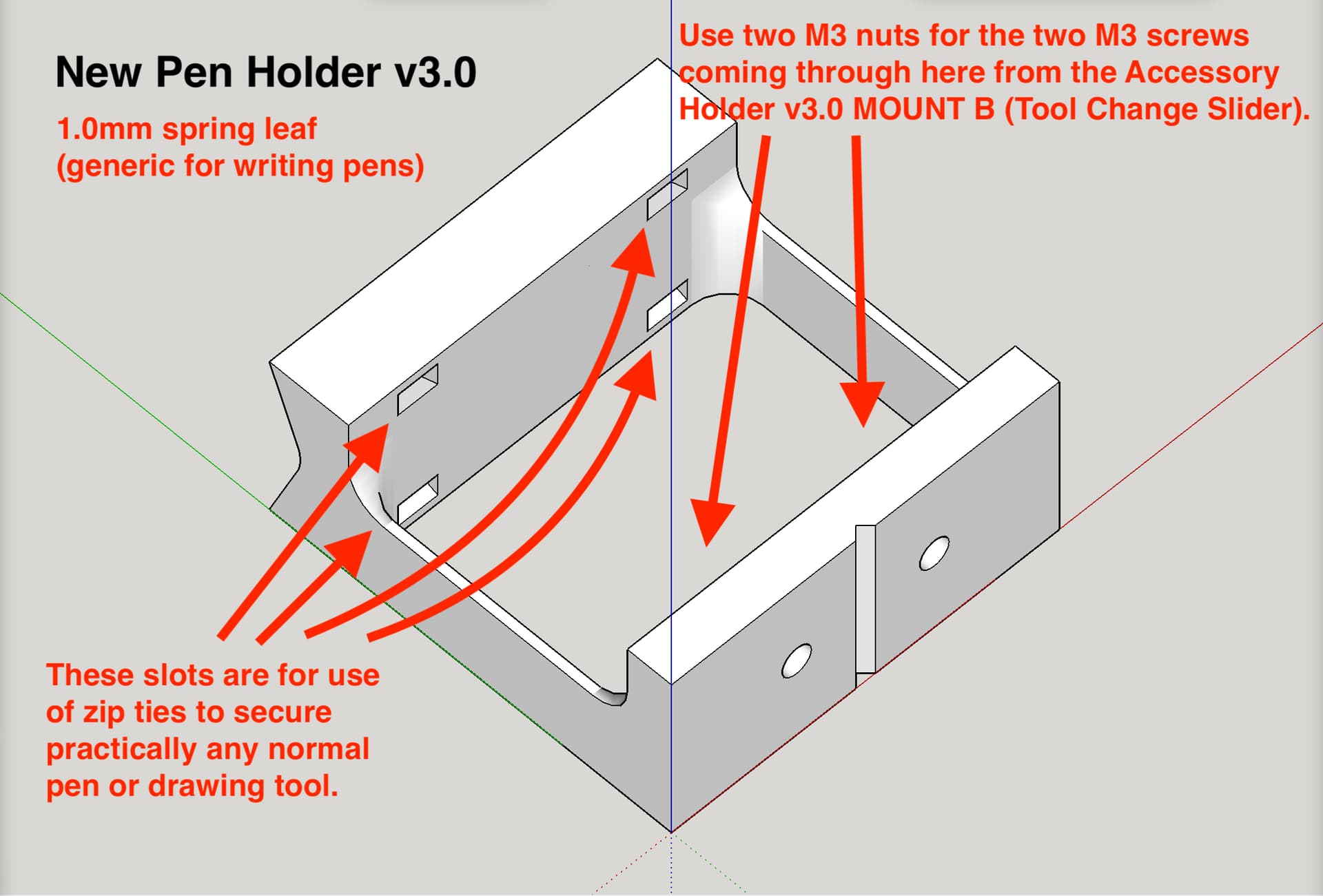
You asked about why I did not have that wedge shaped mount to be a built in part of the tool mount. Where possible I did. For example, the laser diode mount has the wedge and the tool mount as a single print job. However, for the pen holder drawing part, the layer adhesion issue means that I needed the wedge oriented in one direction, yet because of the spring-leaf feature of the penholder I needed the layer lines going the perpendicular direction. So those had to be two separate prints.
Your suggestion about the notch with the tab that hooks into it, is an idea worthy of consideration. In the meantime, one approach to get a tighter fit, is to increase your flow rate on your printer console, while leaving the speed the same. This would be the equivalent of temporarily increasing your E steps, and would deliberately nudge the printer toward over extrusion, making the parts slightly thicker and fatter. This would — in your case — give better clamping, affecting the friction between the cam lever and the edge that it’s trying to lock against.
yes, I did check it before printing. However, on your suggestion I checked it again and it seems to be off again. Strange. I reset the parameter a few times and after each test it is off again. Will need to troubleshoot some more what´s happening.
Now I was printing other parts and they were good. Anwyas, will manage to fix it.
Yes, indeed.
Swapped the motor, modified the settings 3 times and now it seems to hold.
I just reprinted it (tool mount b) but the fit remains the same. Even thinks it is slightly more loose then before as it just drops out without effort.
So “creep” is a term used to describe when plastic under tension will stretch or deforme overtime. It can cause parts that once fit tightly to become loose. I think I will make two or three variations of the cam lever part that allow for sprucing up a tight fit, with a reprint of the most minimal amount of plastic.
Also, since the track is wedge shaped, I can remove the “ceiling” / top stop and make it so the upward motion of installing the tool mount wedge is not concluded by reaching that top stop, but rather by when the wedge achieves contact, so this would mean a tight fit no matter someone’s level of under extrusion or over extrusion. I should have thought of this at the start!
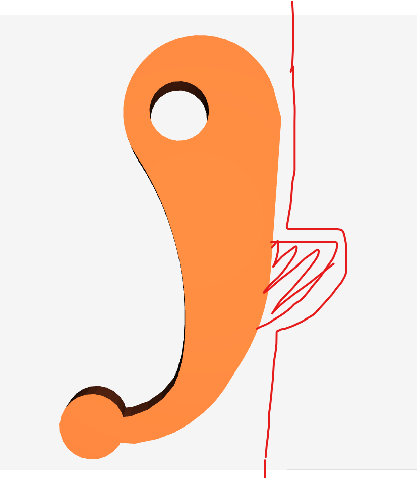
could you please update the latch to make it a bit wider?
I have the exact same experience!
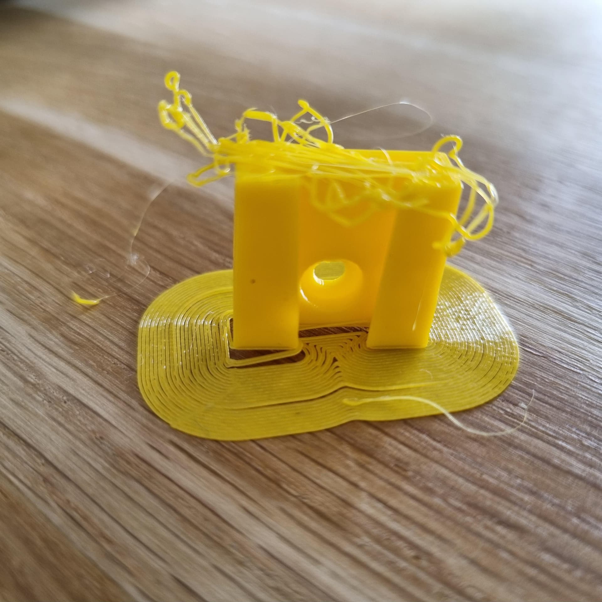
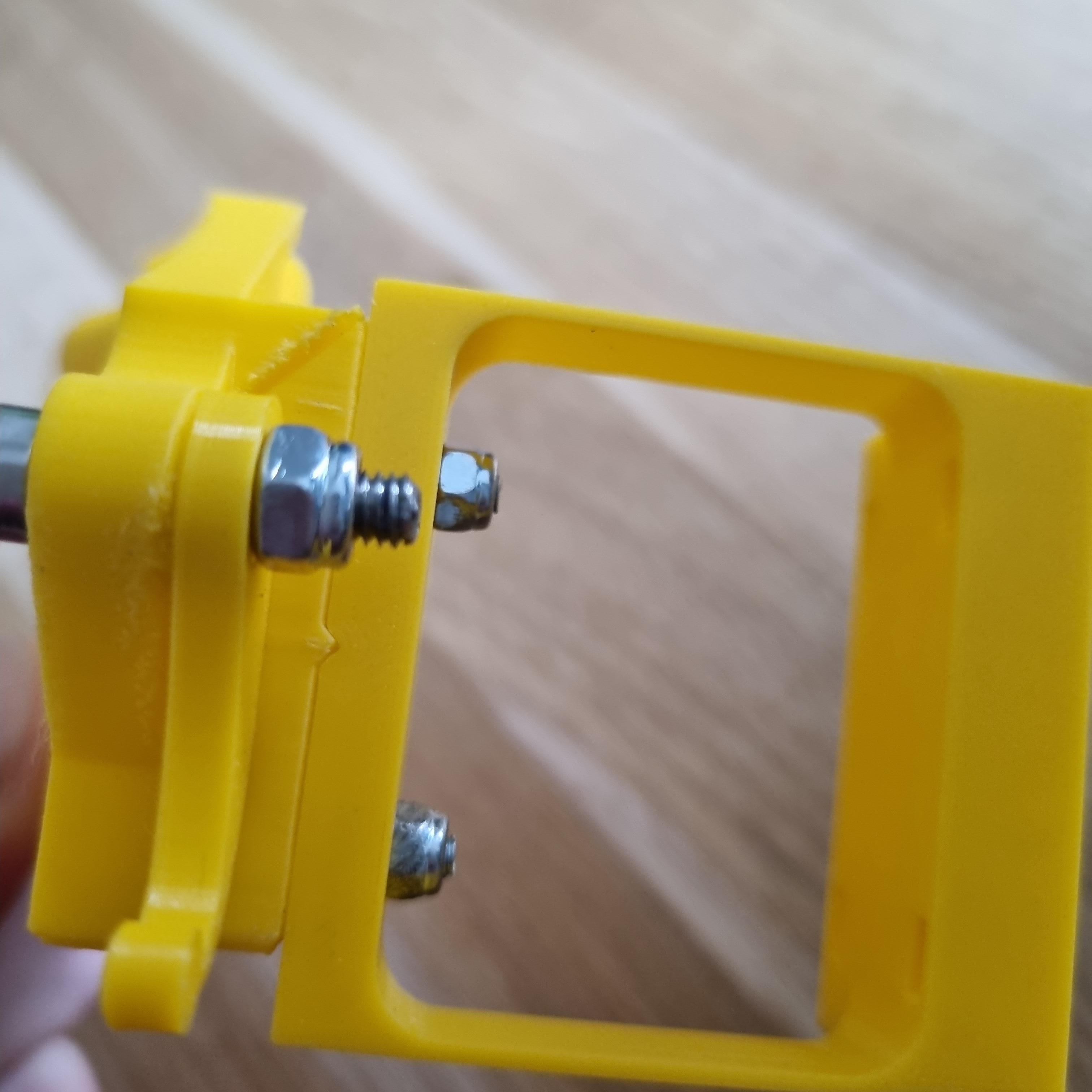
I’ve printed it on the X1C and it does not hold very well, only by force but not by the „latch mechanism“ itself (it should hold because the latch gets bigger while pushing it down)
I’ve recorded a video:
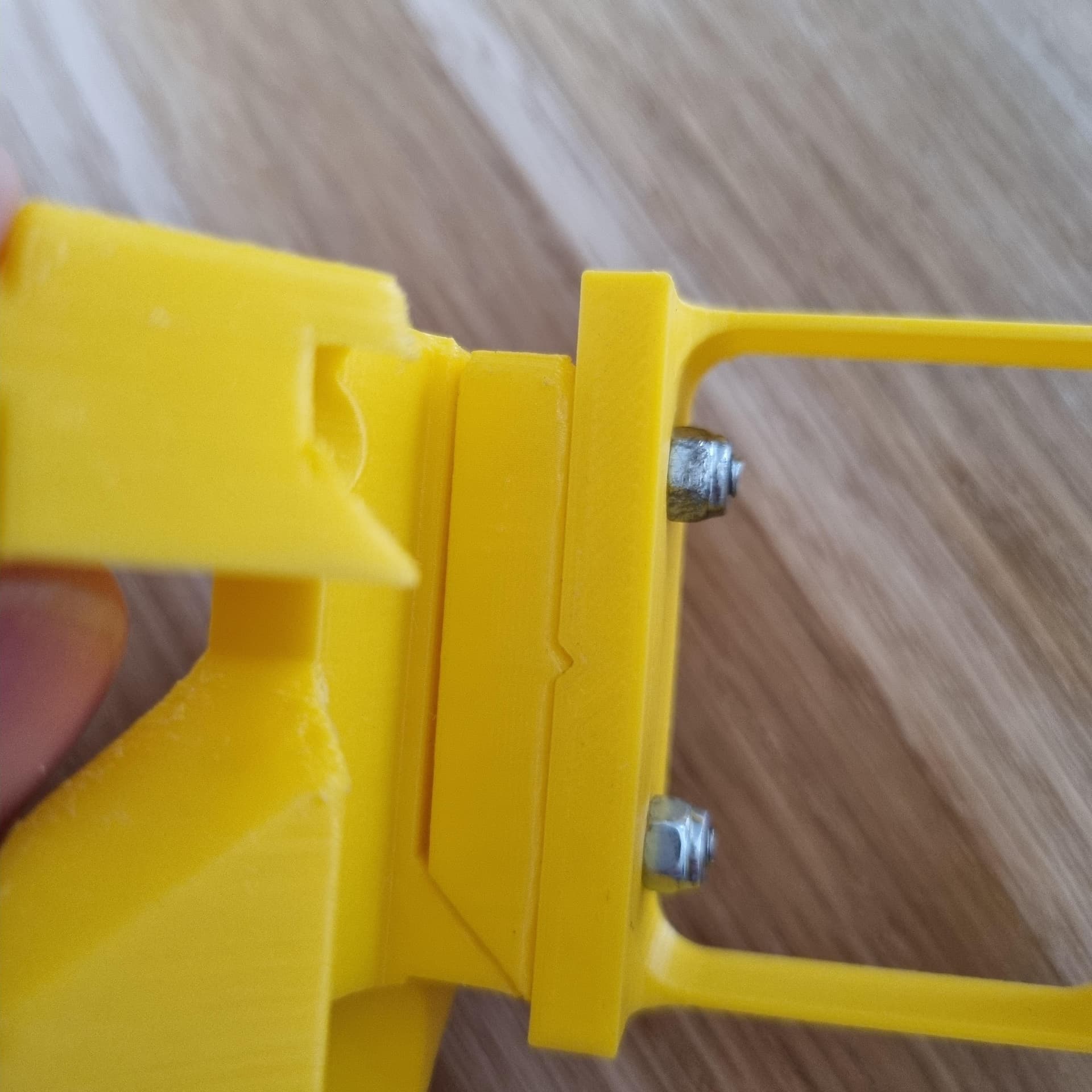
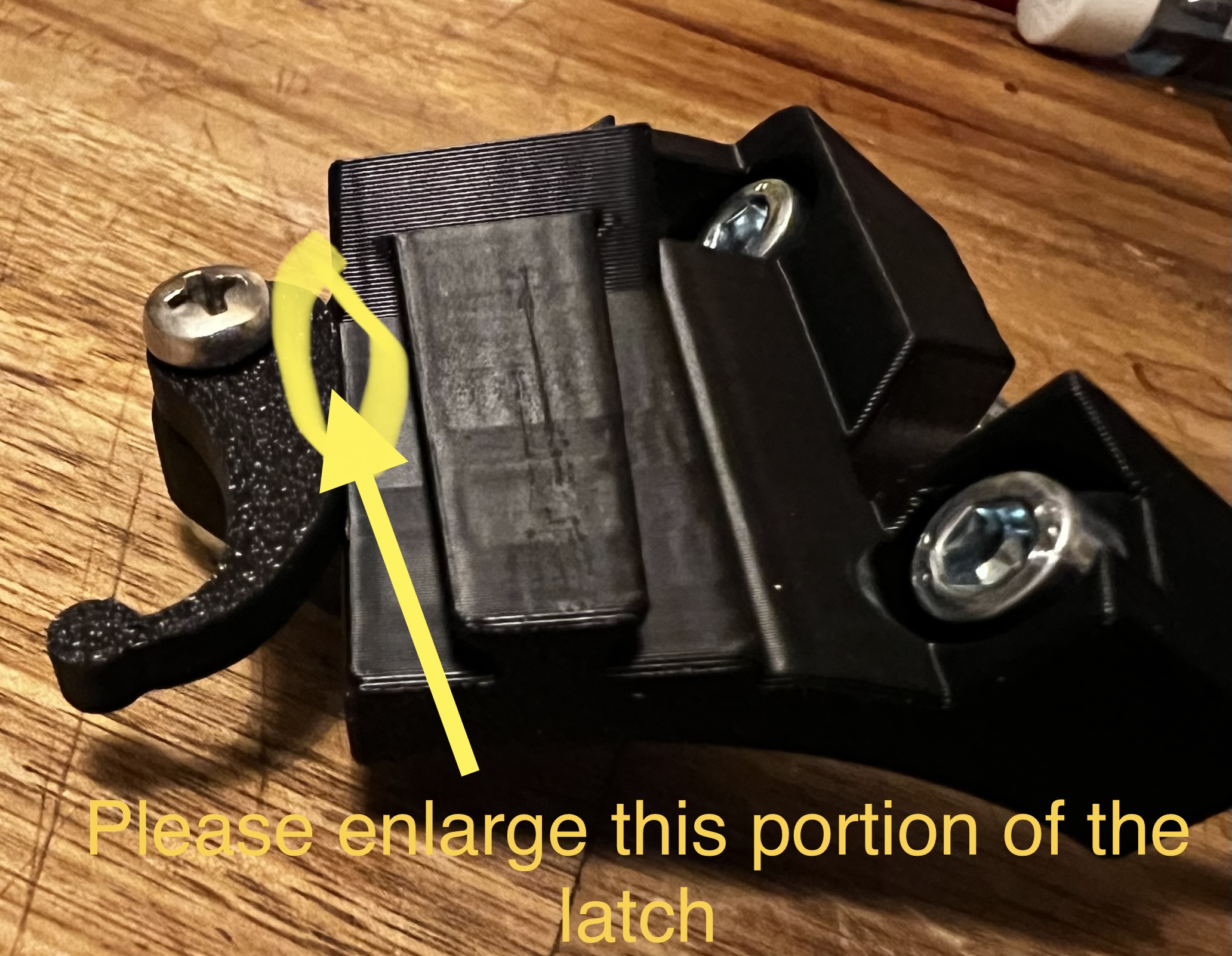
And a photo for the requested improvement.
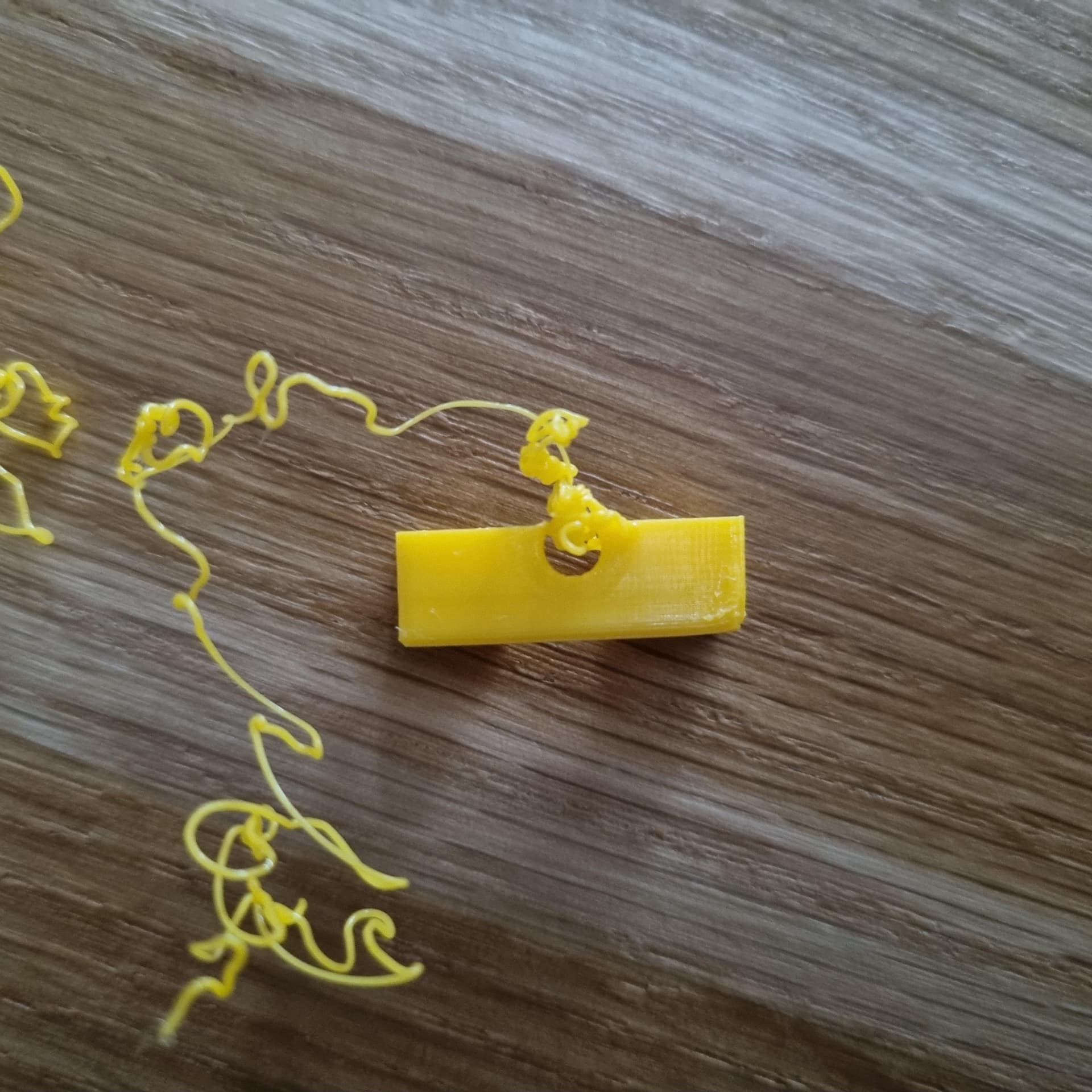
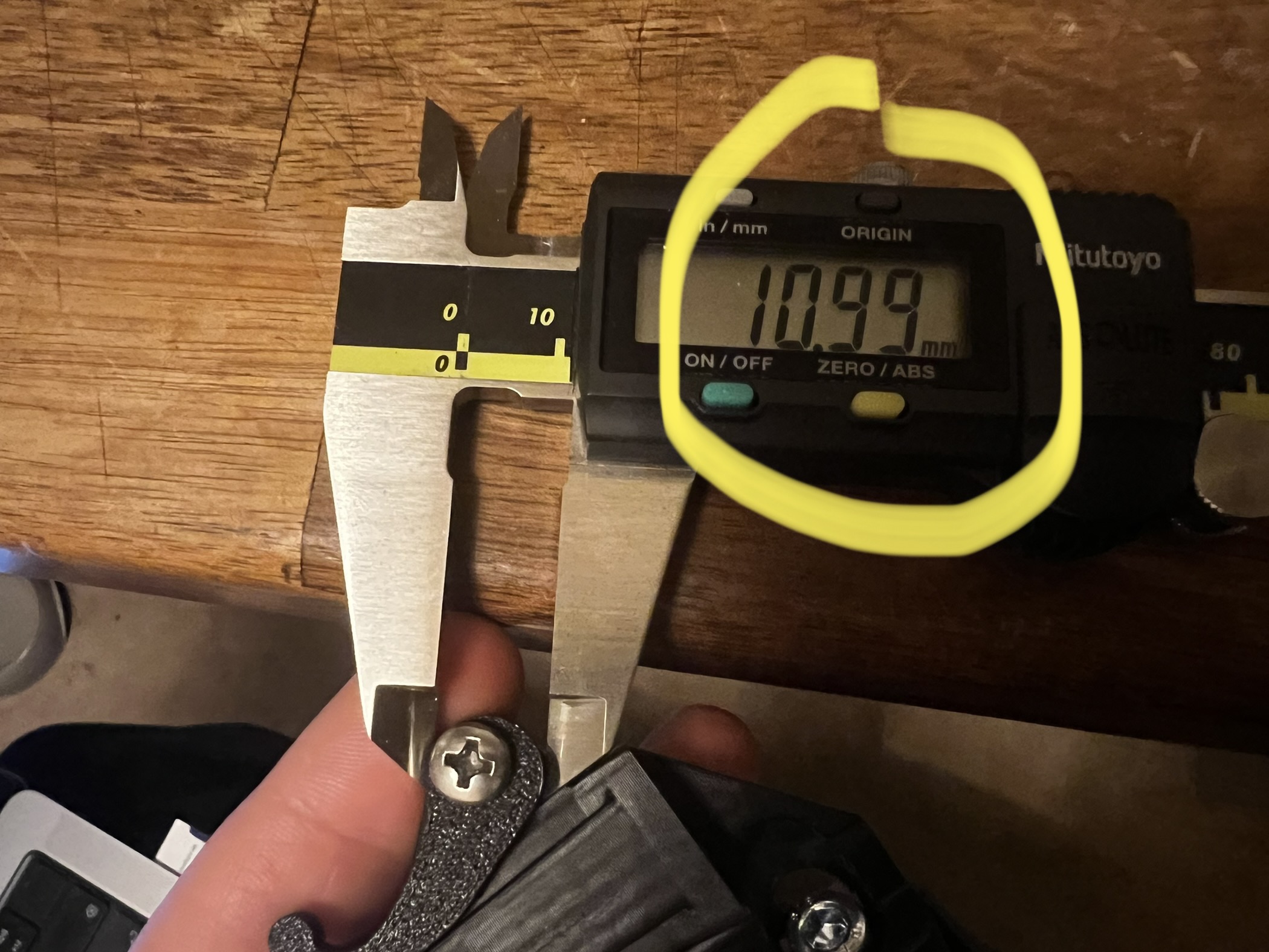
I’ve measured the latch itself, my print is 100% accurate with the file (measured 10.99mm and it should be 11mm (measured in prusa slicer))
If you want I can print myself some scaled versions of the latch (1%, 2% larger etc.) to give you an better estimation of how much bigger it should be.
By the way, I had a nearly identical issue with the screw holes on your awesome TFT35 (non E3) case.
One suggestion:
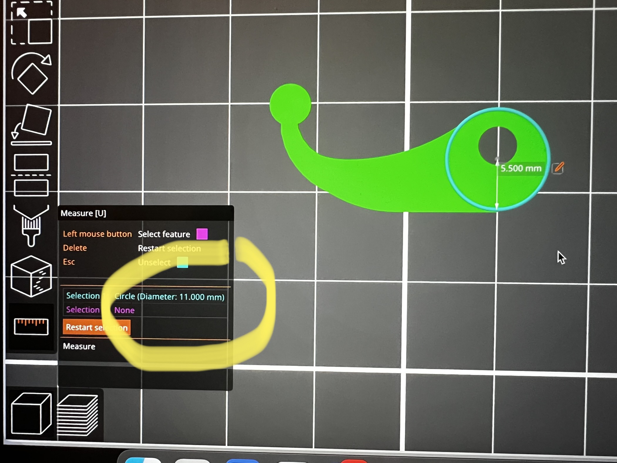
Maybe it’s a good time to measure your printed parts if you can, like the latch, if it has a 11mm diameter, like in my pictures above.
If I would guess, I think your printer does have a lower accuracy/higher accuracy margin and that’s why a couple of things are working in your case.
@CNCMaker
Since I’m overhauling this (as mentioned above), it might be better to wait and check fitment on the newer version of it. It’s pretty much ready to upload now (Version 3.1).
Suggestion:
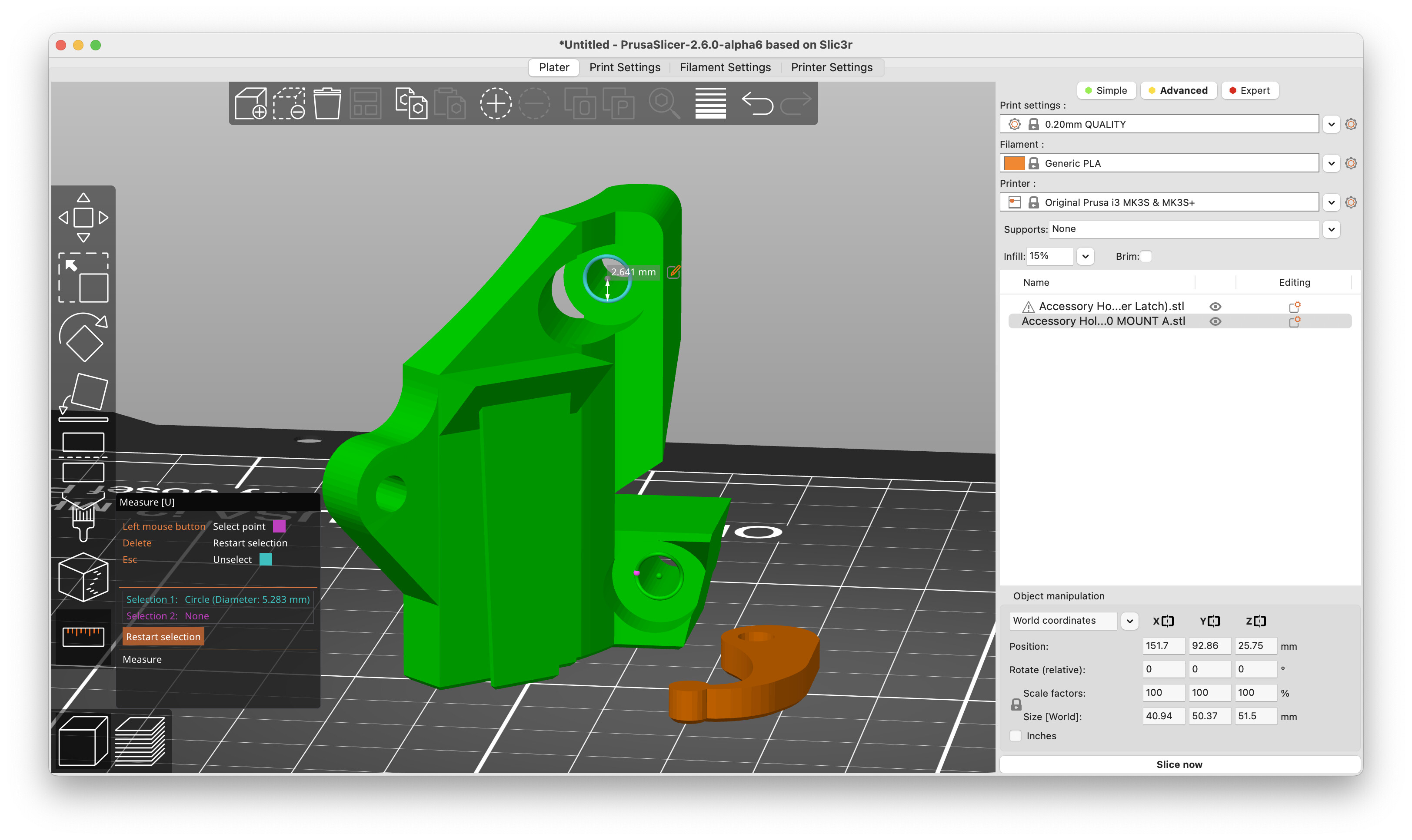
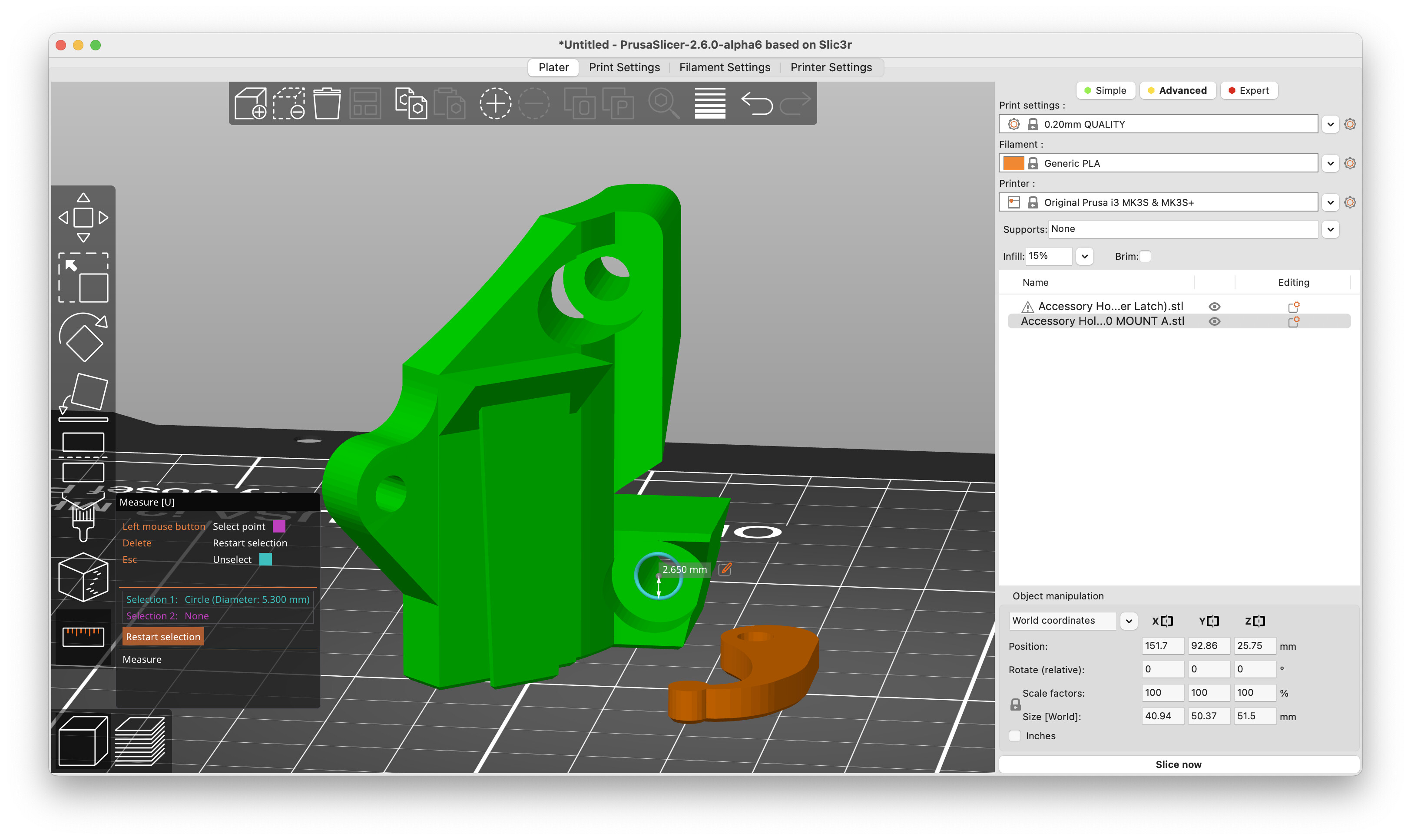
Could you please make both 5.200 mm? That would be a perfect fit and from what I know “common” in the 3D space for a M5 hole.
(A M5 screw does have an official diameter of 4.480mm)
This technically ought to be a “clearance” hole instead of a hole for self-cut threads, so the larger size is probably more proper. But I’m OK with it being 5.2mm.
This chart for clearance holes says that “tight fit” clearance hole for M5 is 5.3.
1.) Own real life experience:
I can tell you that I can still „push the screw out without turning the screw“ for the 5.283mm hole. That’s what lead me to a diameter lower than that.
3.) The answer from ChatGPT, it’s suggesting the the same number (5.2mm):
Question:
What diameter should a M5 screw hole have if I need it for an object that I am printing on my 3D printer? (The printer is very accurately calibrated)
Answer:
For an M5 thread, the screw hole in your 3D print should have a diameter of 5.2 mm. This is because M5 is a metric thread with a nominal thread diameter of 5 mm and the thread usually has a pitch of 0.8 mm. To ensure that the screw easily engages with the thread and securely fastens, it is recommended to use a screw hole with a slightly larger diameter of 5.2 mm.
However, note that 3D printers are not perfect and there may be deviations in the print that can affect the actual diameter of the hole. Therefore, it is advisable to measure the diameter of the printed hole with a caliper or micrometer and adjust it if necessary.
This sounds about right, since the goal of a clearance hole is to be able to push through without having to spin the screw. A 5.28 mm hole is pretty close to a 5.3. For that matter, 5.2 is also close.
Where Nominal Diameter is the size of the screw (in this case, M5), Pitch is the distance between adjacent thread crests, and the Constant is a factor based on the tolerance class of the screw.
For an M5 screw with a coarse pitch (0.8mm), the Constant for a medium tolerance class is 0.4. Therefore, the minimum recommended hole diameter would be:
Hole Diameter = 5.0mm + 0.4 * 0.8mm = 5.2mm
So, the recommended minimum diameter for a clearance hole for an M5 screw is 5.2mm, based on the ISO 286-2:2010 standard.