NOTE: June 8, 2023 — improved new release, v4.1, accomplishes two goals:
The pen is located closer to the center point of the LR3’s router (less offset from the cutting bit)
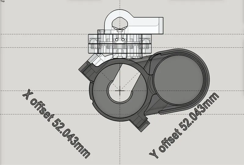
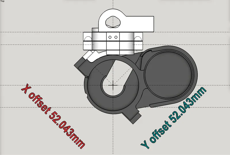
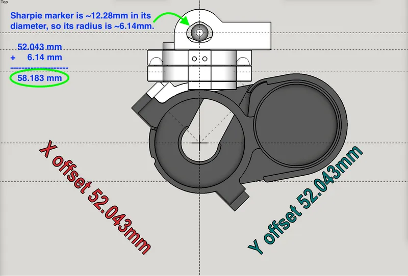
The offset distance is equal in both X and Y axes: ~52.043 mm for each. That’s from the center of the router bit to the edge of the mount where the side of the pen rests. To calculate your actual offset, be sure to add on the radius of your pen body. See example below. (For anyone curious, the 45-degree diagonal measure of offset from router bit center to the edge of the holder where the pen body rests, is ~73.6mm.) Having X and Y offsets be equal hopefully makes it a bit easier to handle coordination between drawing and cutting in the same project.
IMPORTANT ASSEMBLY TIP:
Insert your two zip ties through the pen holder, before attaching the pen holder to the Mobile Base from the linked other listing!
Diagrams showing the X & Y offsets, and an illustration of calculating offset with a common Sharpie marker:
Here’s a helpful video I made about this (the video shows older v4.0):
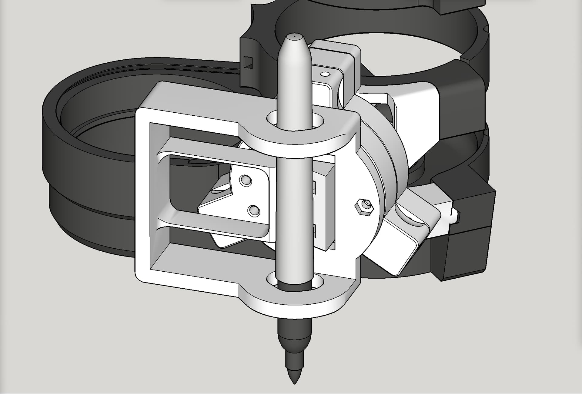
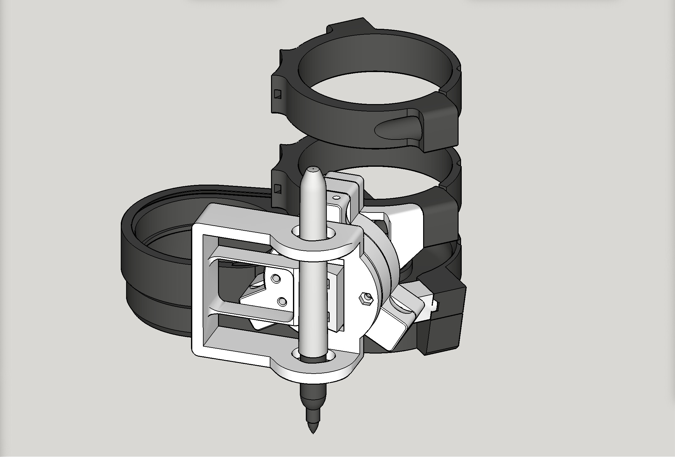
Print, attach to the Mobile Base in the listing above, using three (3) screws and nuts, M3 x 16mm.
Install a pen using zip ties. Attach this and its Mobile Base to the Fixed Base on the LowRider v3, and draw something. Post results in the comments here.
Change log:
June 8, 2023 — improved new release, v4.1. See above.
May 18, 2023 — initial release, labelled v4.0 (because so many previous mixes).
These combined models are looking pretty good. They printed well on my stock Ender 3. I do realize that I didn’t pay attention to print orientation and for the most part it didn’t appear to matter (Yet).
As I went to assemble, I realized that my M5 screws protrude through the plane of the Base for the bottom LR3 mount. Are you using button head or hex cap screws? Most of my metric collection is hex cap, and it LOOKS like it should have fit. However, I did also print this in a different orientation, so perhaps that makes a difference? I’m still learning the ins and outs of orientation for 3D printing.
Several short notes, and also some pics that will hopefully help.
I try to always upload my designs in the orientation intended for printing. I did so with this design.
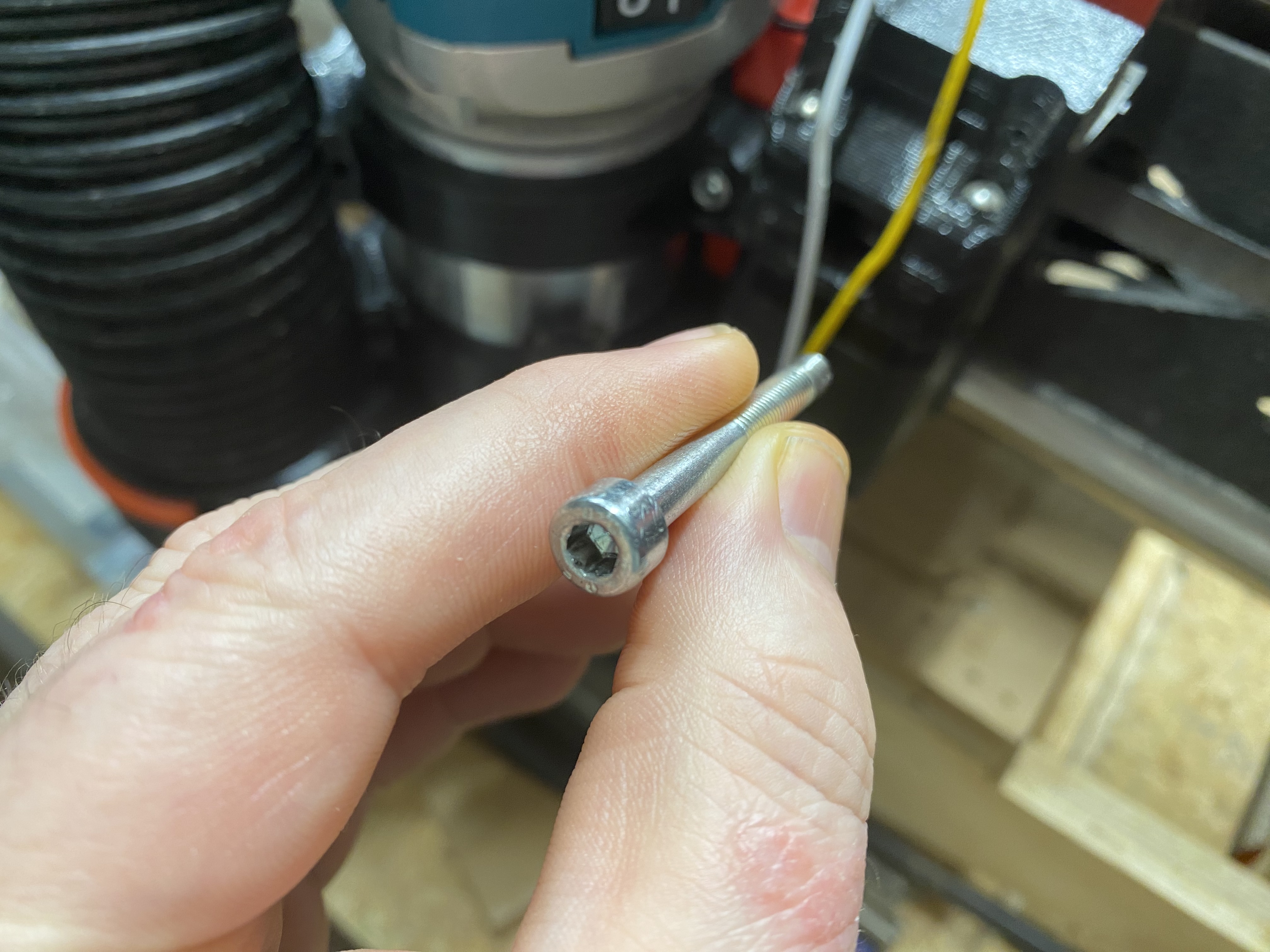
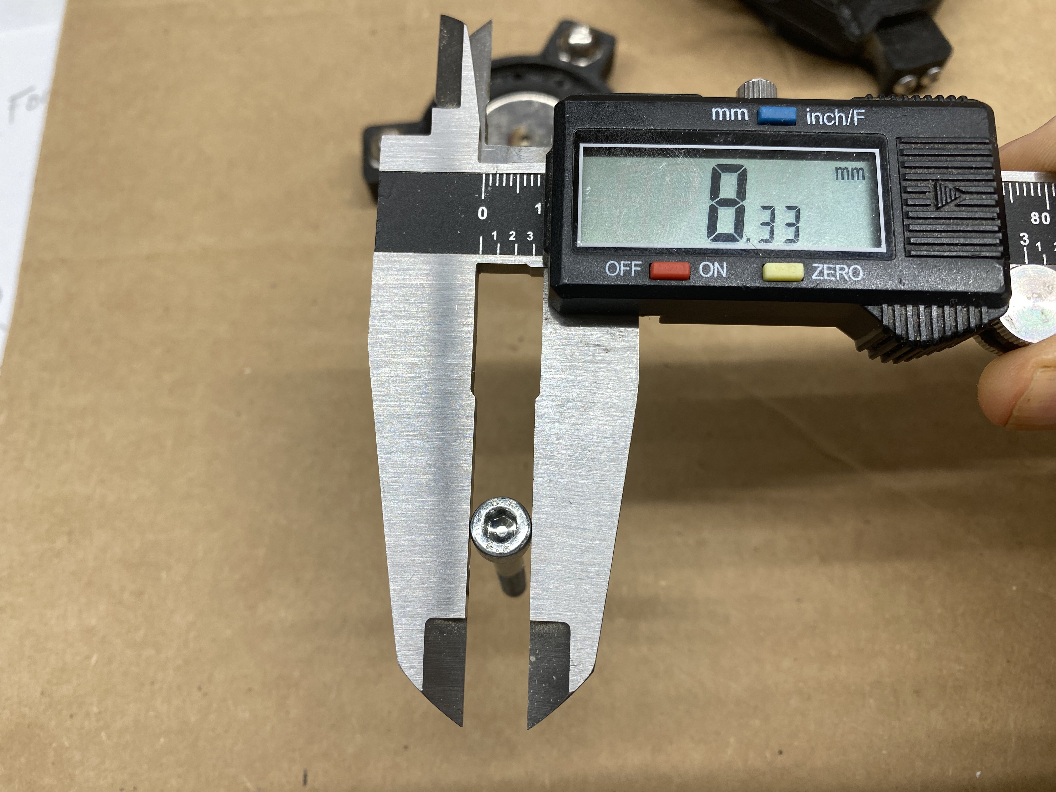
The image below shows the M5 screws that I used, and shows a set of digital calipers measuring how wide its head is.
On my install that screw head fits down inside that printed well. My design has no part of the screw cap/head exposed outside of the main base part.
It looks like either your screws have a bigger head, or perhaps over-extrusion during printing made the well hole for the screw head too small for the head to fit.
My screws are 8.44mm wide and 5.22mm tall. IT does fit horizontally in the well, but it might be a vertical size issue. Additionally I printed it with the well hole facing down, meaning that it was printing on supports and might have sagged. I’ll bet it is the combination of the two that make the tolerances just a bit too tight.
You have drawn attention to a potential issue I may have not taken into account. The top well is shown in photo as not an issue, but now I’m pondering the bottom well.
PS: the well opening (in the 3D modeling software) measures as just shy of 10.6 mm (10.598399 mm) in diameter.
Yes, the top well worked fine for me, it was the bottom well that caused my issue. The top of the cap needs to be below the plane, all the way out to the edge, as that is where one of the three arms overlays.
I figured that I’d try drilling it out to see what would make it fit, and it’s not just filament sag. I had to get into the infill (I printed with 4 walls because it was a quick job and I left my previous settings.)
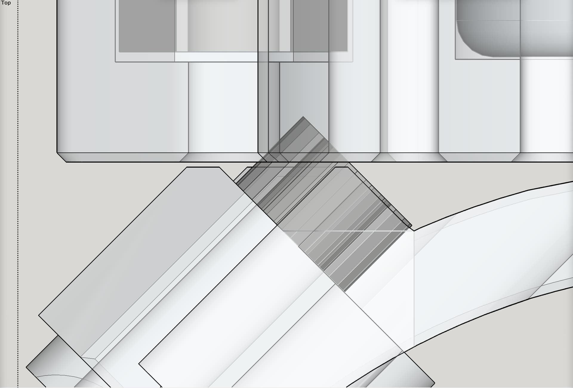
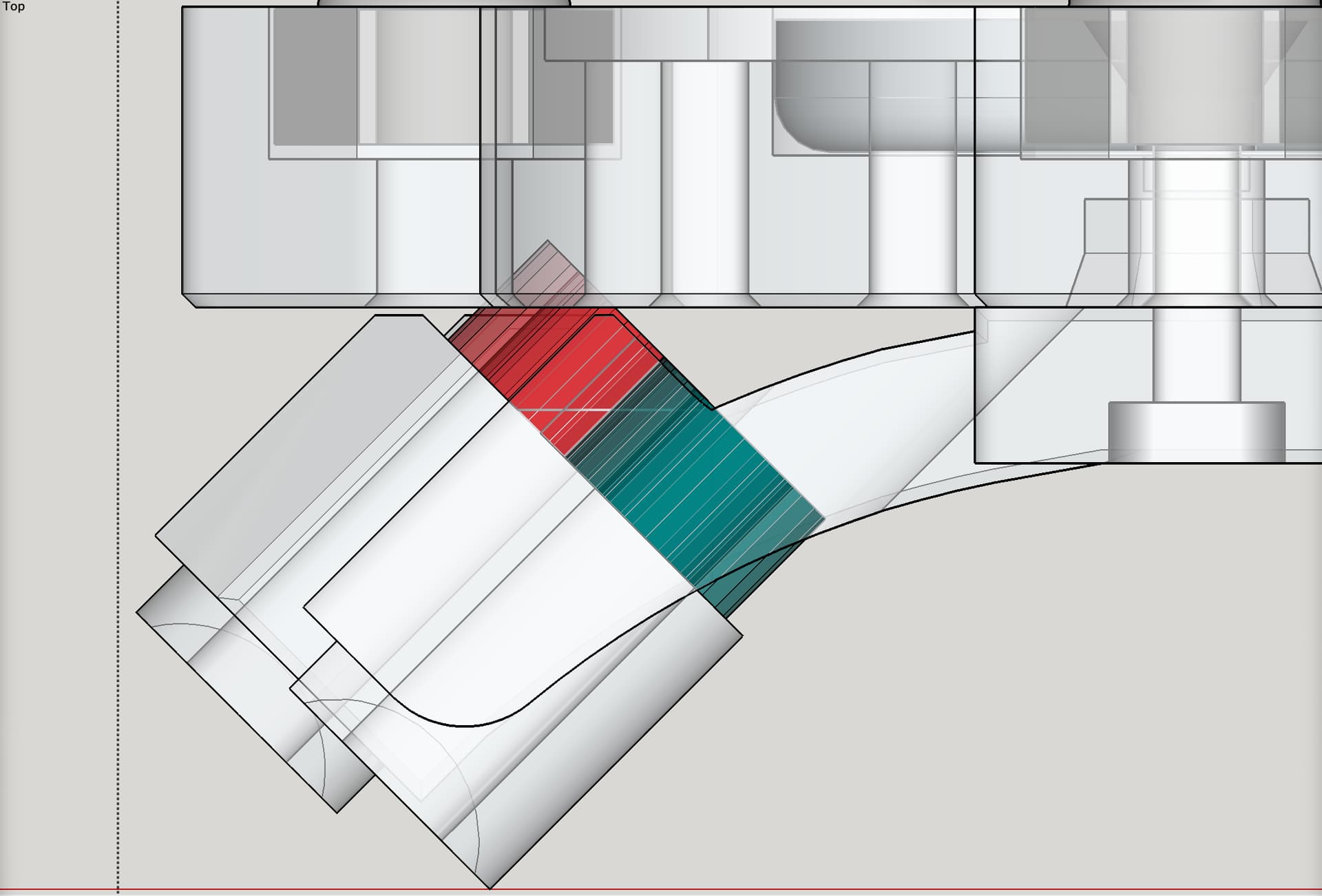
I have just confirmed this is a design flaw — real issue, not your fault. The images below show “without any screw head simulated” and “with screw head simulated.” The simulated screw is based the size you are using.
In this screen shot, the red is the lower screw head, while the green is the upper screw head, seen from directly overhead (straight down vertical view).
I printed @jamiek’s Base because I didn’t have cap nuts. In theory, we could notch it out on that one, but I don’t know if that would work for the version with nuts?
I don’t know what the intentions of this mount are, but for lower torque applications Potentially the bottom screw could just be set deeper, with the risk of a bit less strength holding it to the router mount.
How tall are the cap heads on your screws? They must be shorter if yours worked.
The easiest fix is to “sink” the screw well in deeper on the bottom one. However, that would allow the screw to penetrate deeper into the LR core, and I don’t know whether there is enough leeway for that to not cause any collisions inside the LR core’s operation and travel path. Trying to check.
Sinking the lower well by 4mm is enough to accommodate your 5.1mm screw head. My screw head measures 4.9mm tall. I’m guessing 5mm is about average. So the questions are:
Can an extra 4-5mm of screw be tolerated inside the LR core?
Would folks want to cut off 4-mm from the bottom screw, or simply using a 40mm screw on the bottom, while staying with a 45mm on the top?
Apparently I’ve screwed my Fixed Base to the Main Mount multiple times without ever noticing it was a bit crooked every time…
Out of curiosity, I grabbed a random assortment of M5 Hex Cap Screws - I got heights from 4.9-5.4mm Some of the discrepancy was probably from trying to grab the small ledge with my calipers, but I did notice a trend that my longer ones seemed to have the upper tolerances slip higher.
I wonder how much variation there could actually be from different Manufacturers and Different materials. I’d guess you’re right that the spec is probably 5mm, but that would mean up to .5mm in variation each direction - so it might just come down to buying “better” hardware.
If sinking the well by 4mm will more than accommodate a 5.1 mm head, then by 4.5mm would accommodate up to 5.6mm. If I can verify that 5mm of leeway exists inside the core, then that would be my plan.
Good news: I have confirmed that there is plenty of leeway inside the LR core for the lower M5 screw to be 4.5 mm further in, so I am deepening the screw well on the Main Mount.
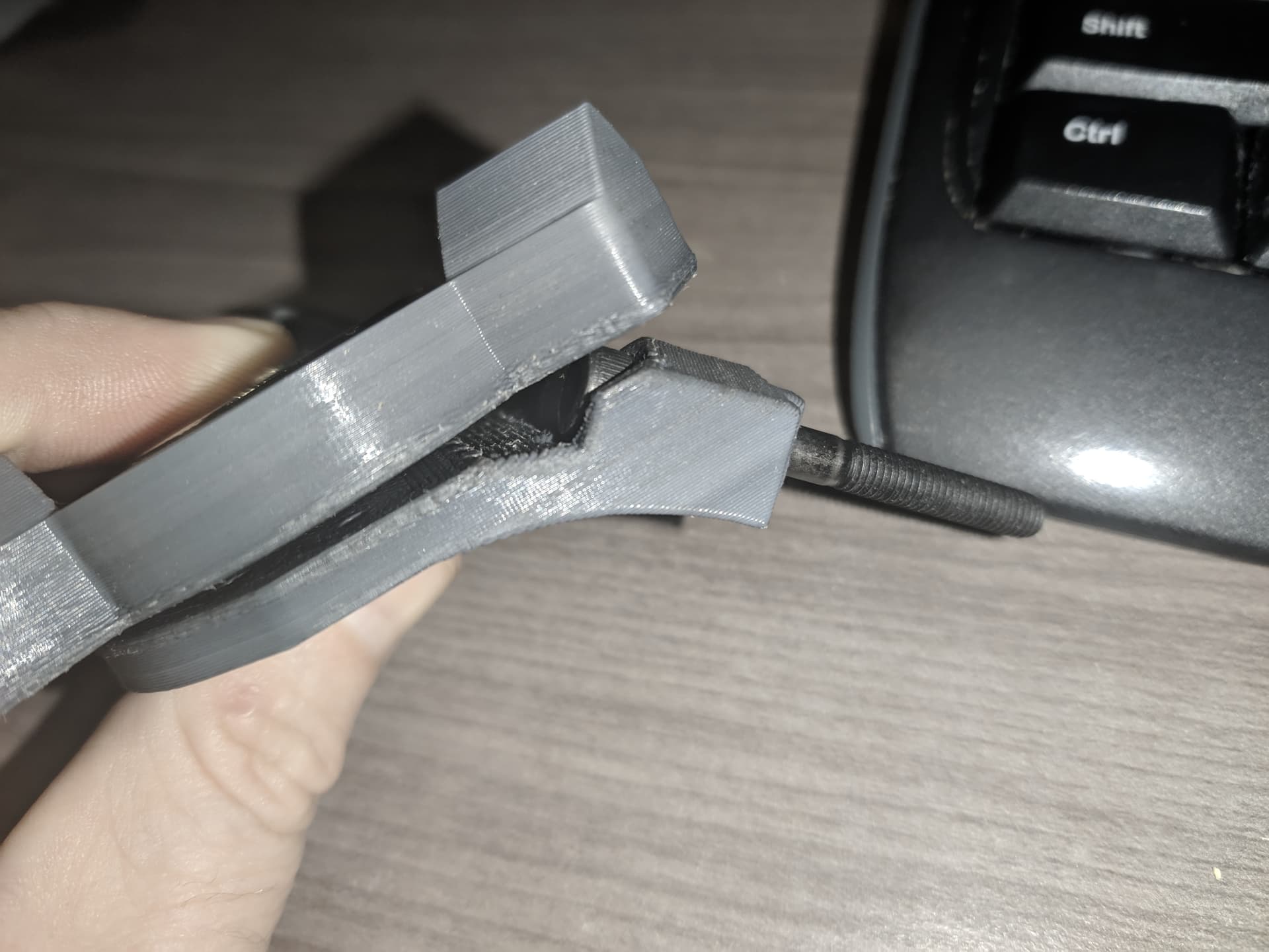
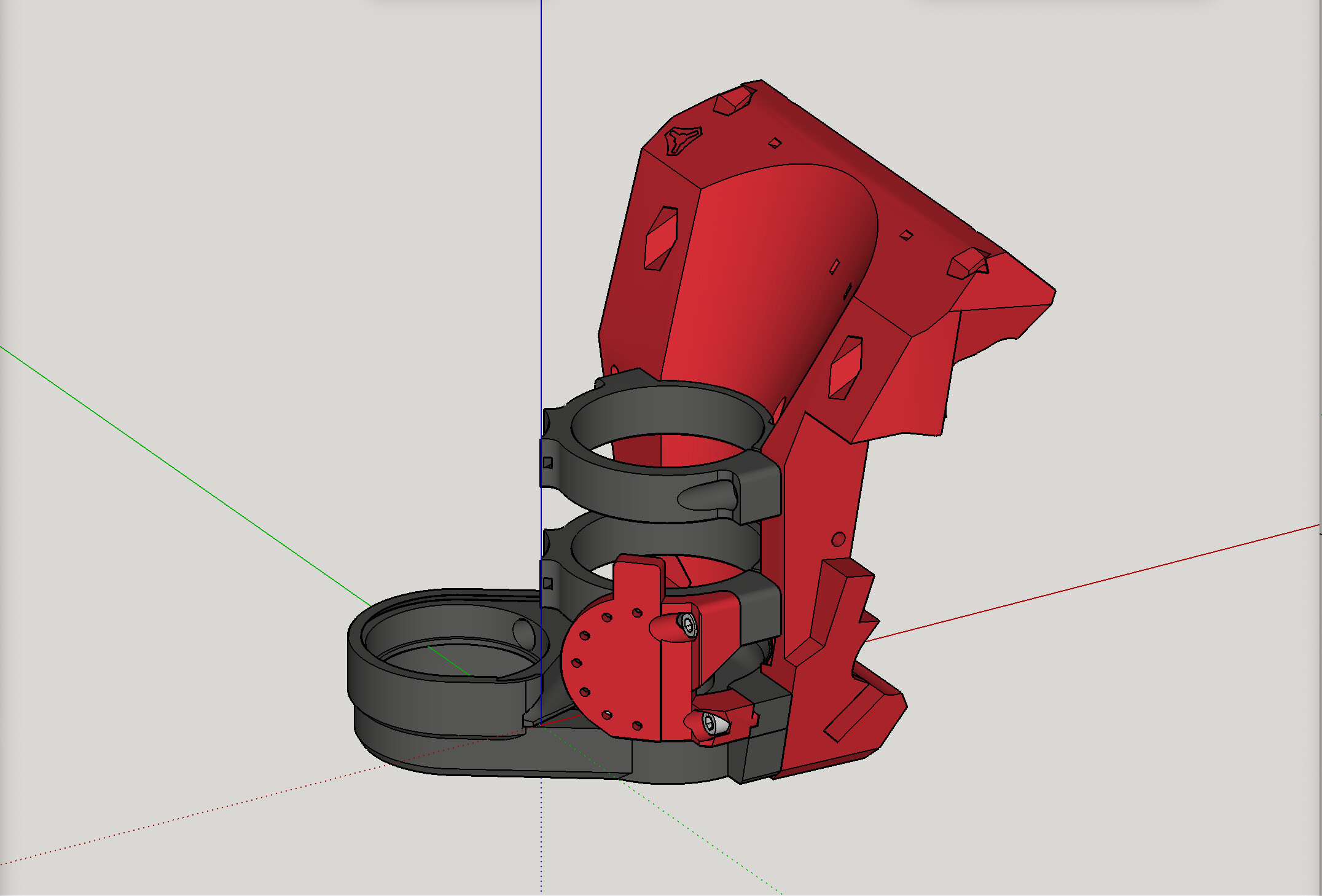
In this image, the red is the screw. You can see the tip end is not clear of the hole in the back of the LR core:
Wow, it looks like we just lucked out… much further and it might be rubbing the bearing? I pulled one of my failed cores out to get an idea of how close this is. I like it! It keeps the BOM simple!
I see that @jamiek posted a file. I will fire up my printer this weekend for tests if there is anything else that you’d like me to try.
Overall you both have done an amazing job with the designs! Although I can’t show my nieces the 6 color pen plotter or that’s all it will be doing!
I have added the following text to the Updates section:
June 9, 2023 — Regarding “Part A, Main Mount - mounts to LR3 Core” part being updated to v4.1: This new revision has a deeper screw well on the lower M5 mounting screw hole, to fix an issue of collision with Part B, which was caught and reported by fellow V1E maker Kris (**@**KL2001 on the V1 Engineering forum). Kudos to Kris. Thanks for the heads up. Also, watch for more new updates soon that will simplify making this tool mount, and the BOM for it.