Here’s the video I made about this!

Here’s the video I made about this!
Have you guys got any idea what the load required is? I guess in technical terms I’m asking what the refrigerator separation load is?
I suspect that there’s a bit of overkill there. As mentioned a long way above, I’ve sketched something similar/not similar. I was inspired by the mag switch concept, and all my magnetic dust connectors are alternate pole magnets so I was just trying to minimise the bulk of the connection.
You have me inspired enough to print and do some load tests, but I don’t think I’ll be allowed to bolt to our refrigerator!
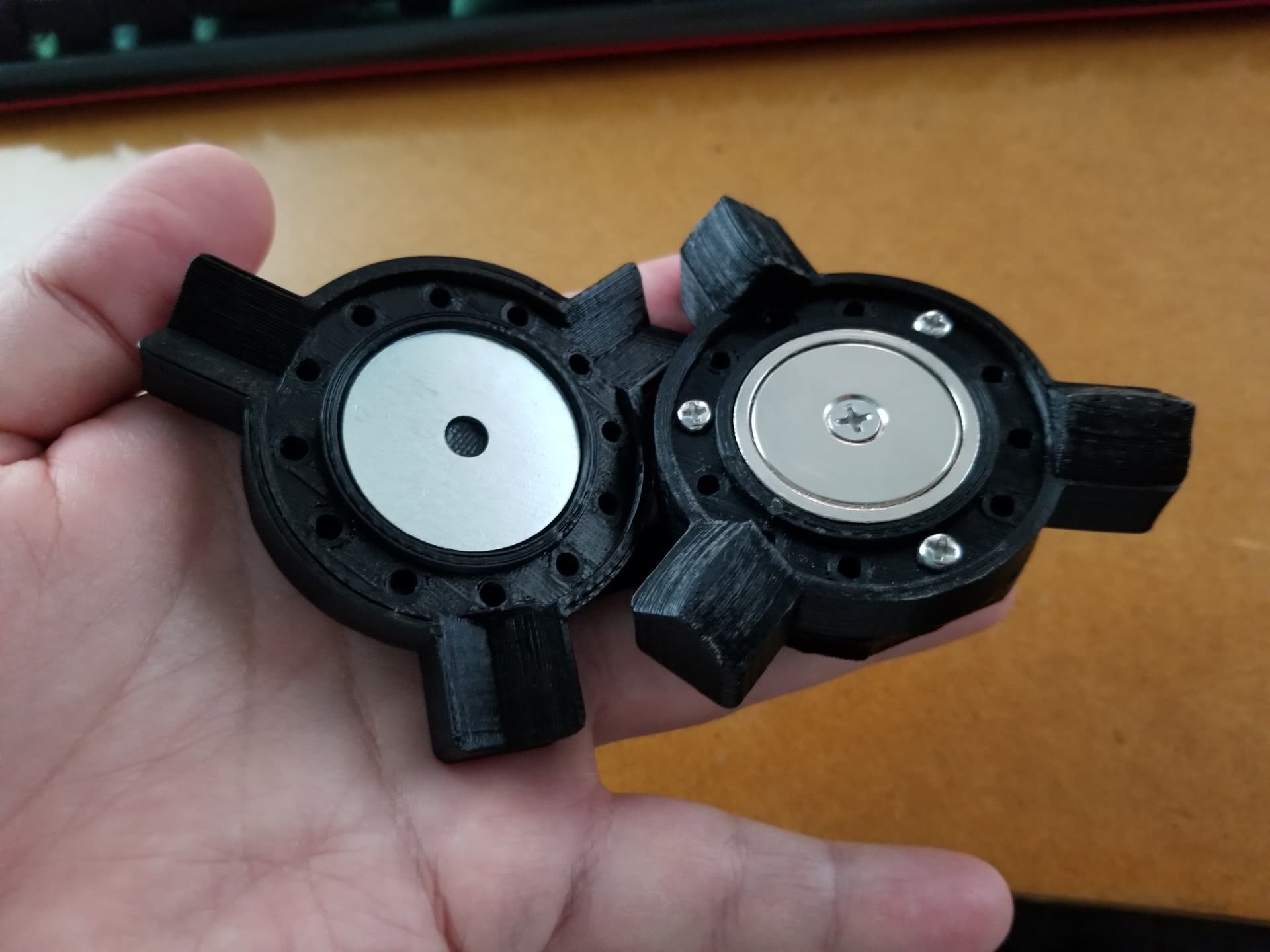
I’m not trained in many of the proper engineering terms. If you are asking about how much force it takes to separate the two coupling halves, it depends on several factors, and some of those factors are controllable, so the amount of force required is literally adjustable. In the case of this design, the amount of force required (synonymous with my term of “grip strength”) can be increased pretty dramatically by (on one side) prying a disk magnet out of its metal cup and flipping it over and reinstalling it. In either configuration (medium strength with magnet not pried out, with metal cup facing out on one side, and high strength with magnet pried, flipped, and metal cup facing in on one side), the amount of attraction can be dialed down by making a slight increase in the distance between the coupling halves, by editing the base so the acorn nuts protrude more. The “medium strength” grip is certainly “acceptable” for use with pen and laser, and might be OK for drag knife use. The “high strength” grip is definitely overkill for pen and laser, and perhaps even overkill for drag knife use. With the added leverage of a long tool holder, such as the “inverted” pen holder model based on @jamiek’s , I can easily enough dislodge the two halves on the high strength coupling. However, with smaller tool holders, such as the one for a NEJE diode laser module, I can hardly break the grip without using a screw driver tip as a prying agent.
Yep I get that - I’m not terribly technical when it comes to engineering either - I was just wondering how many kilograms (or pounds if you must ![]() ) it will take to pull it apart.
) it will take to pull it apart.
You’ve convinced me to test my coupler - it’s the same in the sense that it’s got magnets and it’s circular, but quite different in concept - I might start another thread so as not to distract from this one!
Sounds cool. I look forward to checking it out! ![]()
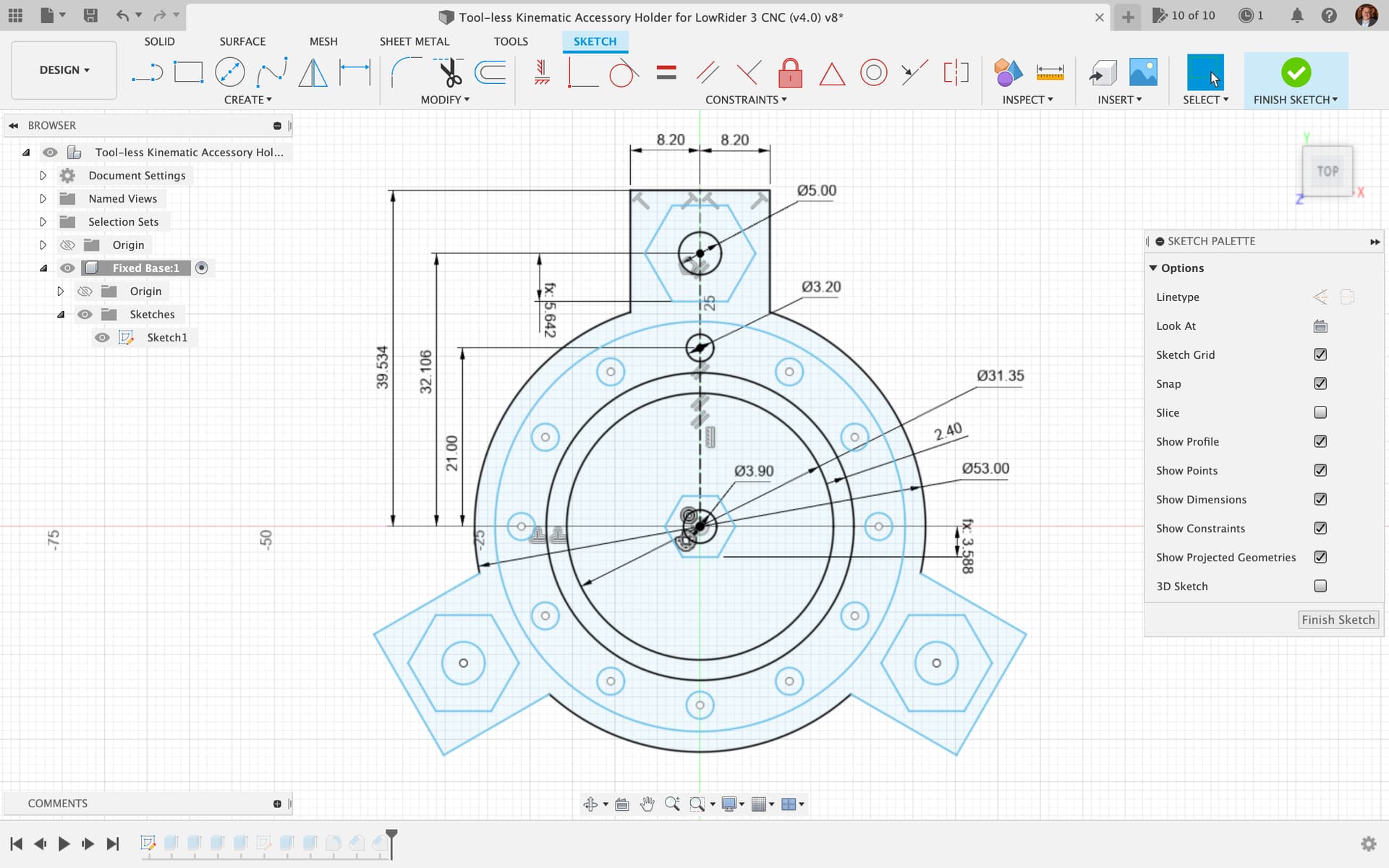
I couldn’t leave well enough alone, so I made some changes:
A kinematic mount with balls and grooves or balls and rod pairs will have six very small contact points. This is not good for plastic parts because the parts can deform with such concentrated load.
The mountains and valleys approach tries to get around this by using grooves with flat sides for valleys and large-diameter sphere segments for the sides of the mountain. This lets it retain the kinematic property. I’m not the first one to think of this. I think they are called canoe balls.
I am thinking it should be relatively simple to maintain a collection of different strength mobile bases for a single fixed base by adjusting the washer depth. I had also considered a threaded washer holder where the depth could be adjusted in small increments, but that seemed like it probably wasn’t worth it.
Here’s a link to the models (including the DW660 mounts):
https://www.printables.com/model/492583-modified-mounts-for-dougs-kinematic-lr3-accessory-
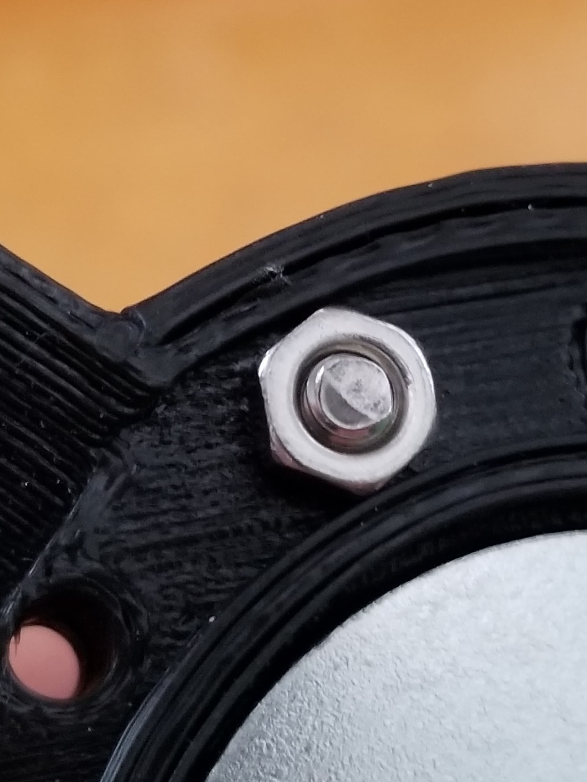
I just discovered that the ring on the face of the mobile base can hold M3 nuts. (Although it’s a bit oversize.)
Is that intended?
The modules for pen, laser, or drag knife don’t have features for holding a nut, so it would need pliers or something to tighten. That’s not the end of the world.
Having the nuts on the facing side could also be problematic if there is a chance a long screw could collide with the fixed base screw heads.
I know, I’m getting too obsessive over details…
My man! Looks awesome. Thanks for the mods and innovative ideas!
Re: did I intentionally make the screw head grooves in the rings big enough for nuts.
I had not explicitly had that in mind — I just gave ample room to make sure a screw head would fit. Good to know!
My initial prototype, which was much much larger, used M4 screws for the grooves that the spheres fit into, and it used the original tapered screws that came with the magnets. However, the whole thing was just too big. And using those tapered screws that came with the magnets meant that the parts had to be quite thick. Are you cutting off the tips of the tapered screws?
I will monitor for any deforming over time. Also, please keep me in the loop on whether or not you’re getting enough coupling force by using the magnets with the metal washers on the opposing side.
The screw for the magnet does poke out the back, and I would have to make a hole in the main mount, or drill a hole, or shorten the screw.
I wouldn’t worry too much about deforming the metal cap nuts or the screws. They should be hard enough, but plastic of the same size would almost certainly be mashed. I will also be keeping an eye on the plastic landing pads to see if they are getting smashed.
I’ll see about measuring the force with different depths. This one feels about right for a pen or light loads, but my hands are poor measurement devices and I don’t trust my intuition. I’ll make some drawings and that will at least be something.
No, it’s called design development, and it’s how a good idea turns into a great one!
What is everyone thoughts on using something like this to have a removable router / spindle?
You want the router as close to the Z as possible. Any distance away and the force on the gantry will be twisting, to the side, and not pushing up. So that’s the first reason not to have a quick change mount for a router.
The second is that you want this mount to be as rigid as possible. If you really want a square setup, you probably also need to have some shims to adjust the final alignment, and that has to be rigidly mounted. Any flex or slop in the mount will be bad for accuracy.
That said, if you are doing sign making or other art, precision and speed may not be as important as convenience. If you want to make that trade off, then this seems like a good choice. You will have to do new tests to make sure you have good cam settings. But as long as the router doesn’t fall off, it should cut.
I definitely don’t want it to fall off. That would be pretty dangerous.
One important distinction to remember here, is the difference between how both screws and magnets act as force multipliers when used in an array. Consider: one or two screws would not be enough to hold a router, but four are enough. That’s what is used. But the force required to remove any one of those screws, stays the same. By contrast, if multiple magnets were used to obtain more holding force in a giant version of this holder, removal of the holder becomes much much harder. With screws, they all work together when holding the tool, but they all work separately when you need to remove the holder. But with magnets, they all work together both in holding the tool and all work together against you trying to remove the tool. It’s totally possible to make one of these large enough, and with enough magnets, to hold a router, but then you’d have the issue that @jeffeb3 mentioned, of distance increasing likelihood of twisting, and the issue of not being able to remove it without major prying, which would add stress to the holder, potentially to the point of bending or breaking the holder.
I don’t want to think about the amount of time I’ve spent talking about drawings vs. illustrations. An unholy union of engineering and legal (another is patent and IP work, but I can avoid that mess).
I have made the above changes to my files for the project, but I don’t yet have the new version uploaded to Printables.
Before doing this project, I had not paid close enough attention to the topic to know that Stainless Steel May or May Not be Magnetic — I had tried first thing, right off the bat, to use a stainless steel fender washer instead of a magnet on the Mobile Base side, and was baffled that the washer would not stick to the magnet. Later, after I had already gone ahead with using magnets on the Mobile side, I finally found out my stainless steel washers were “austenitic” and not susceptible to magnetism.
I went ahead and published (same printables link) all the associated models including hex-mobile-base, multi-pen-holder, and a new extra-flexible pen holder:
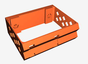
This one uses 0.8 mm walls (2 extrusions at 0.4 each) with perforations to make it extra flexible. For felt pens I wanted a very gentle downforce without having to be super precise on Z.
I’ve included nut holders on all of these to make it easier to attach with the m3 screws. I would recommend adding these to your models since without them it’s a bit annoying to have to hold the nut so it doesn’t spin. With a pocket for the nut, it’s a non-issue.
Will do!