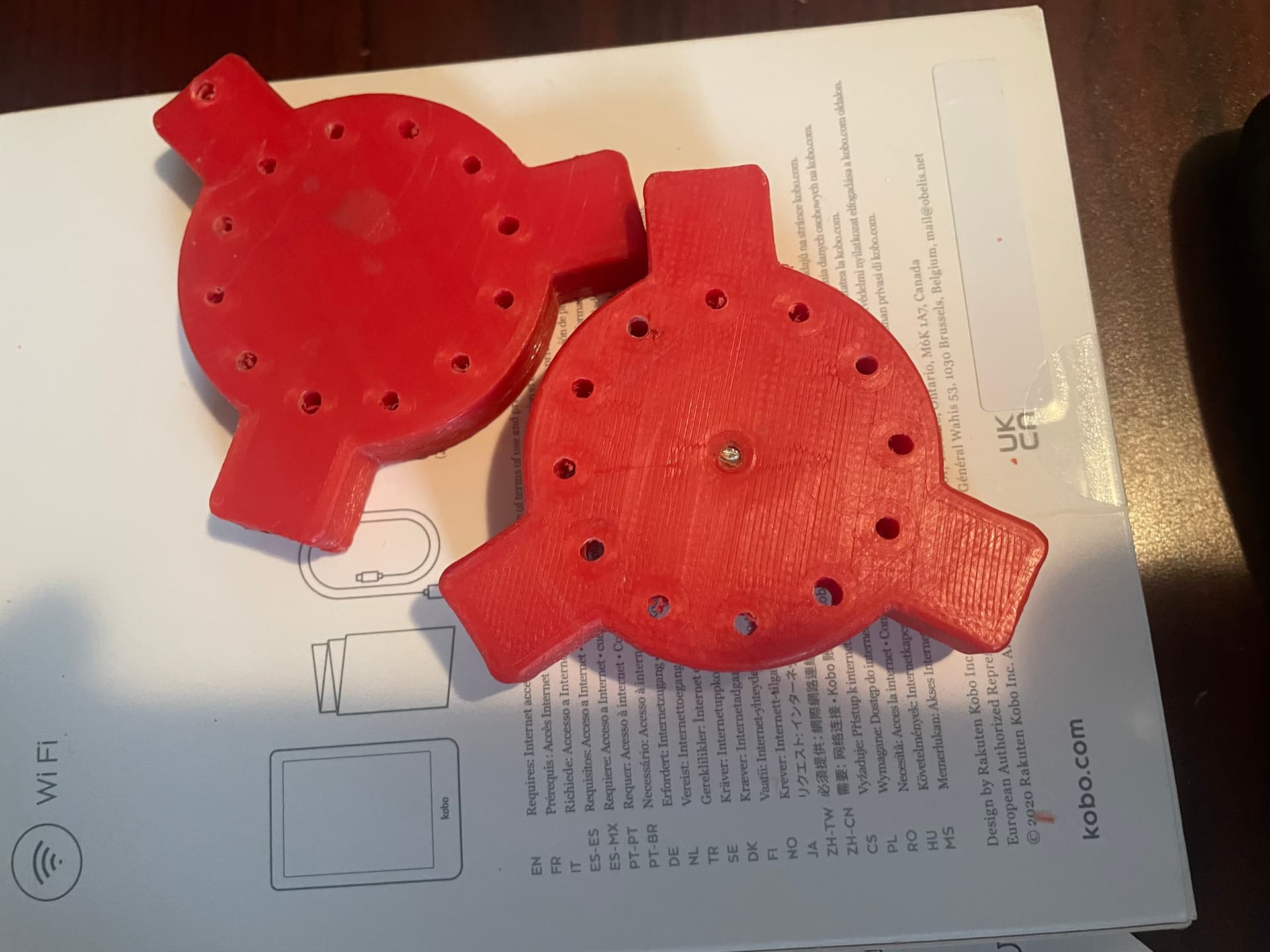
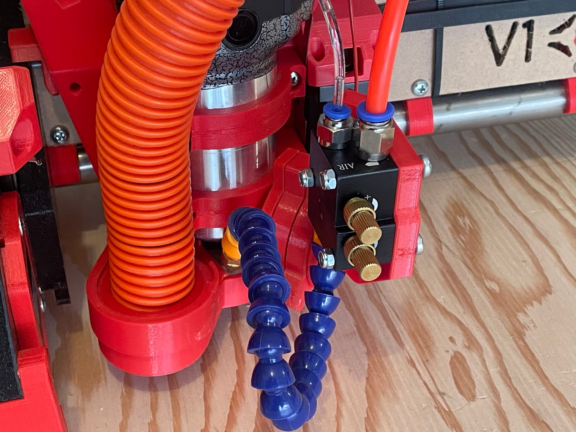
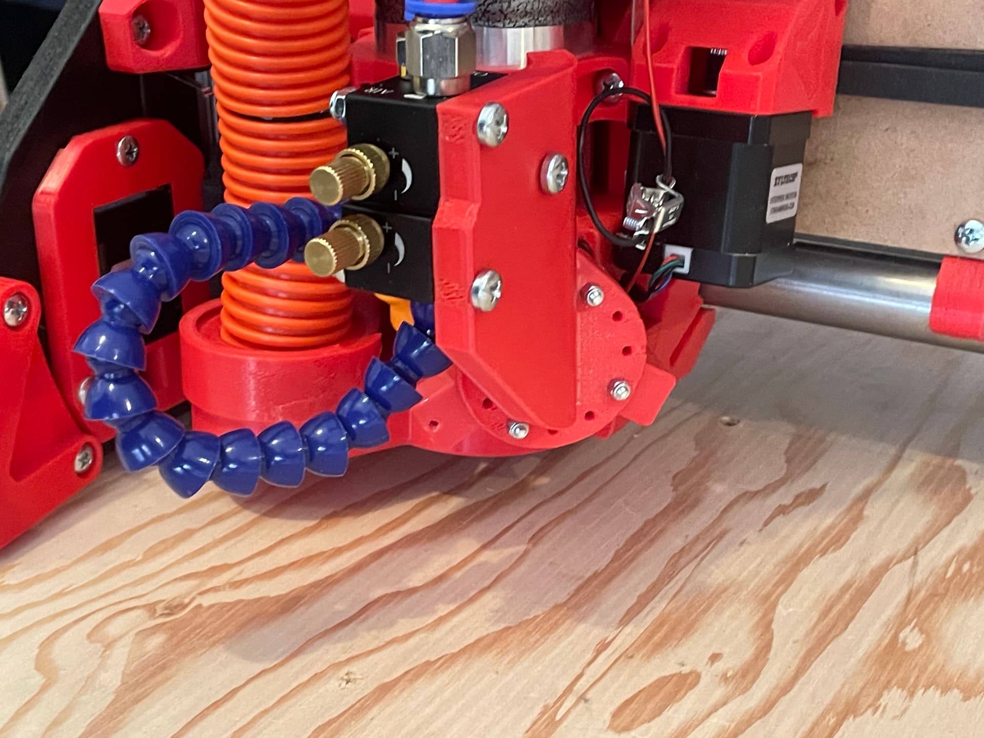
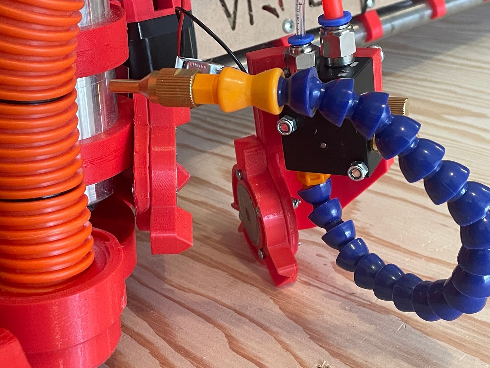
Parts B & C - @jamiek’s “mountains and valleys” remix
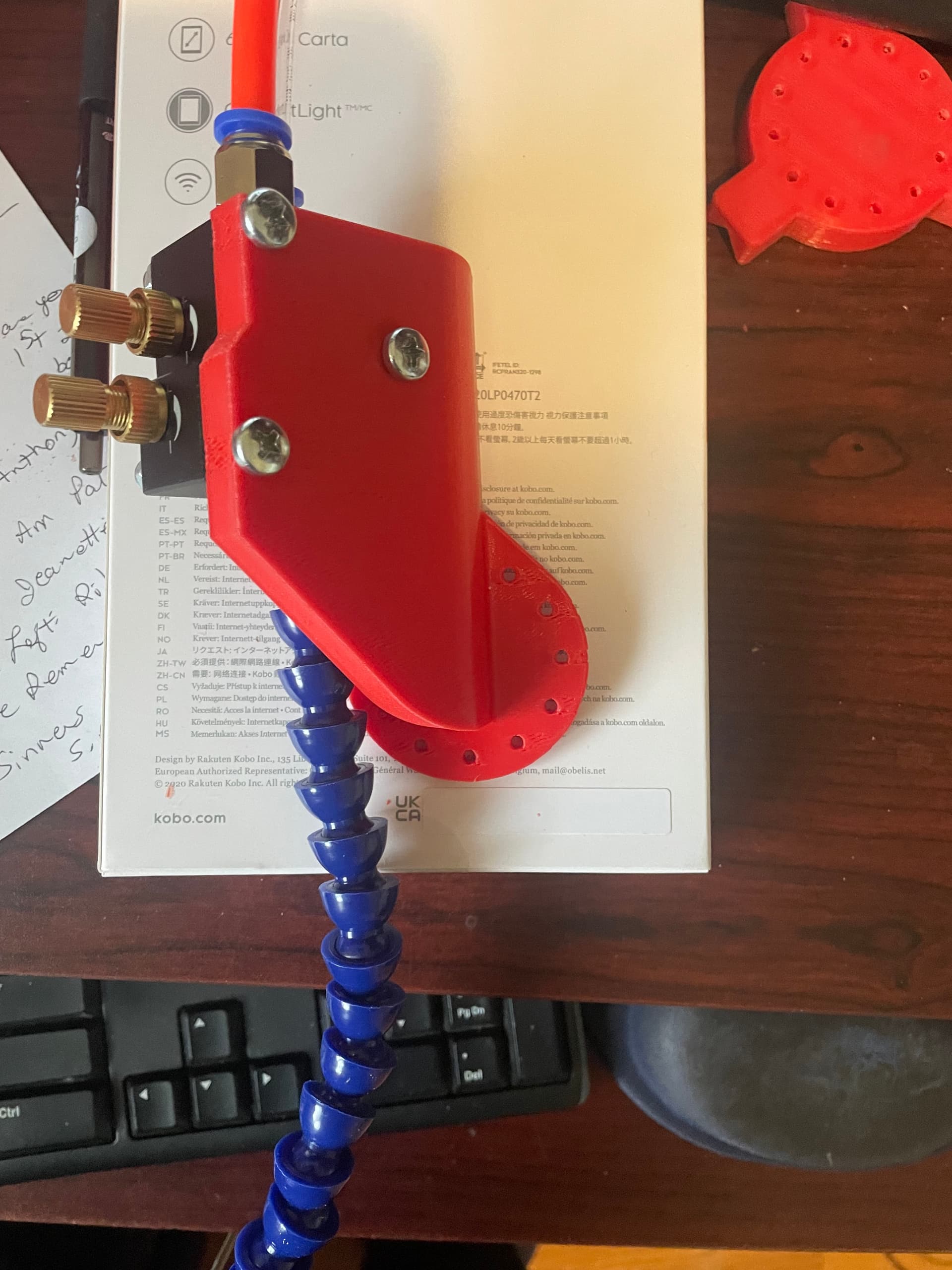
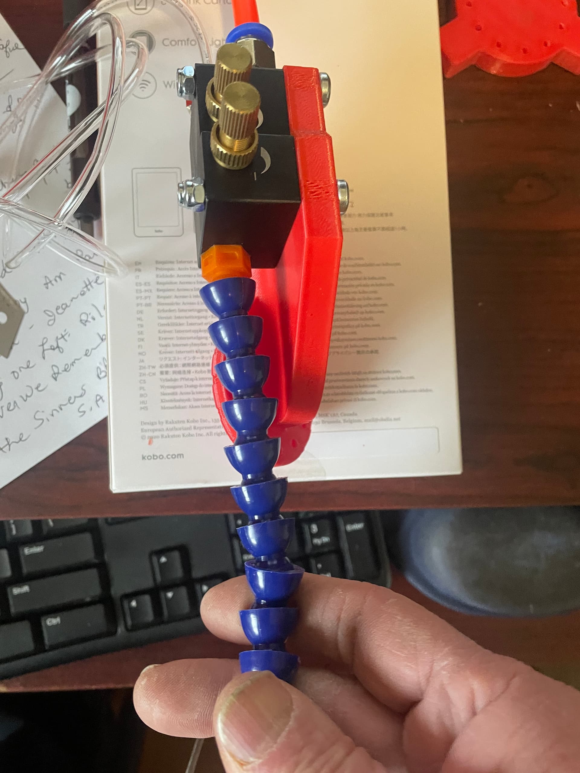
Air Mist Holder - @DougJoseph’s angled remix “Side B”
There were a few hiccups along the way…
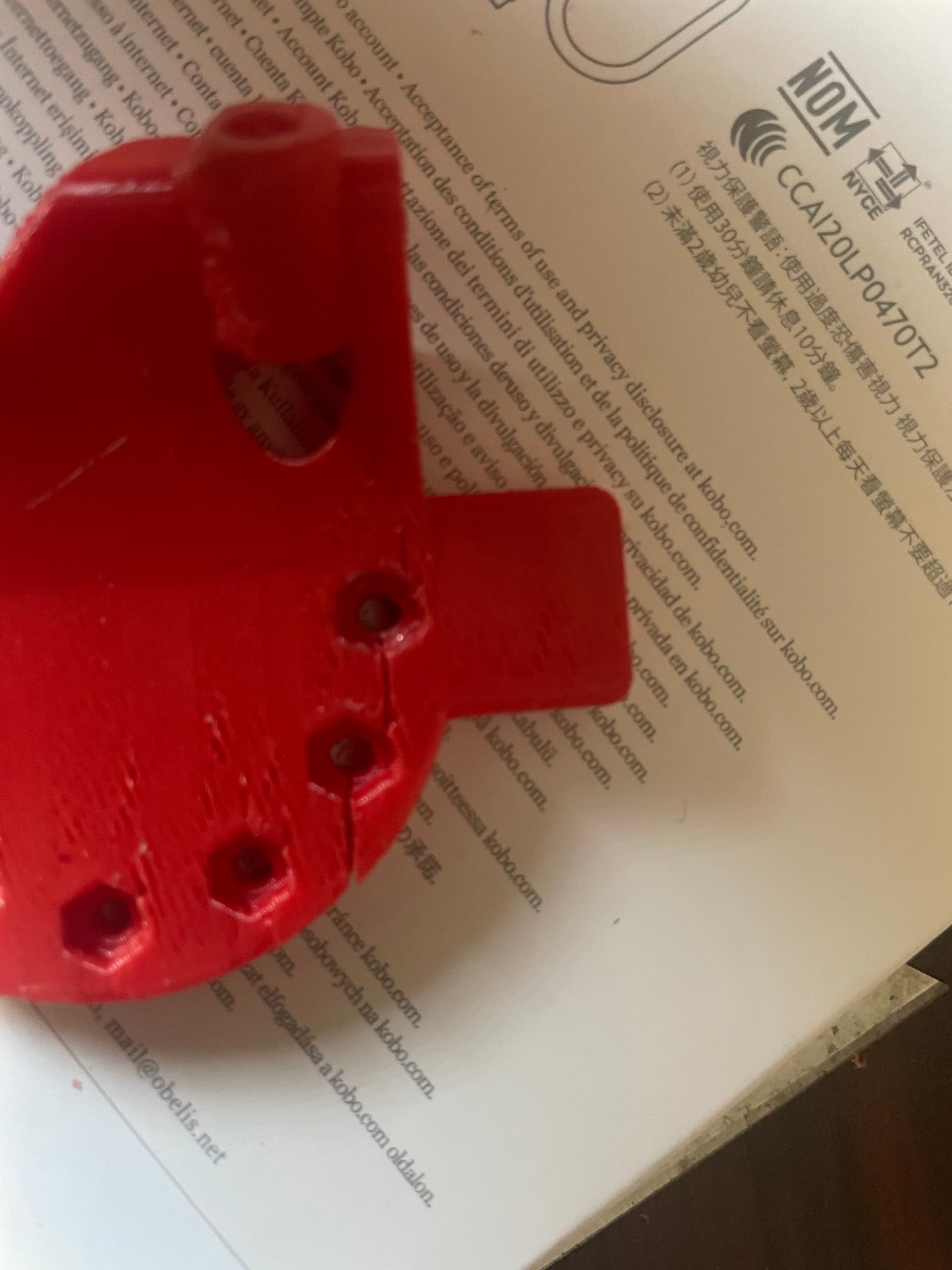
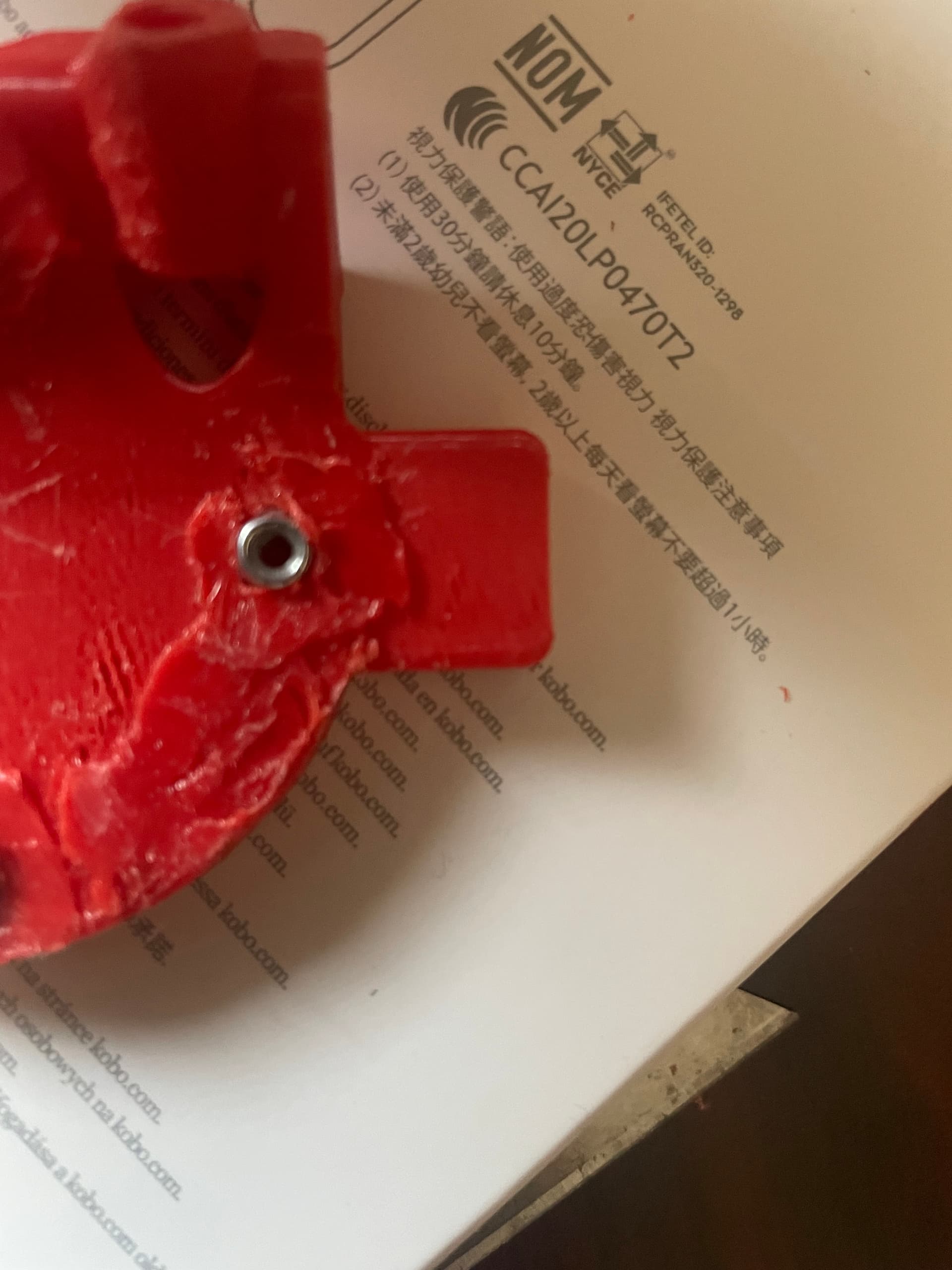
For the base (part A), I found that the captured nut recesses were a bit small (maybe my nuts were too large - wait, that didn’t come out right). The first time I tried installing the nyloc nuts, the printed part cracked at the recess:
I printed another one, and used a heat gun to soften the PLA as I pressed the nuts in by hand, but it cracked again in the same place, although not as severely. I used the solder gun/extra PLA method to repair it.
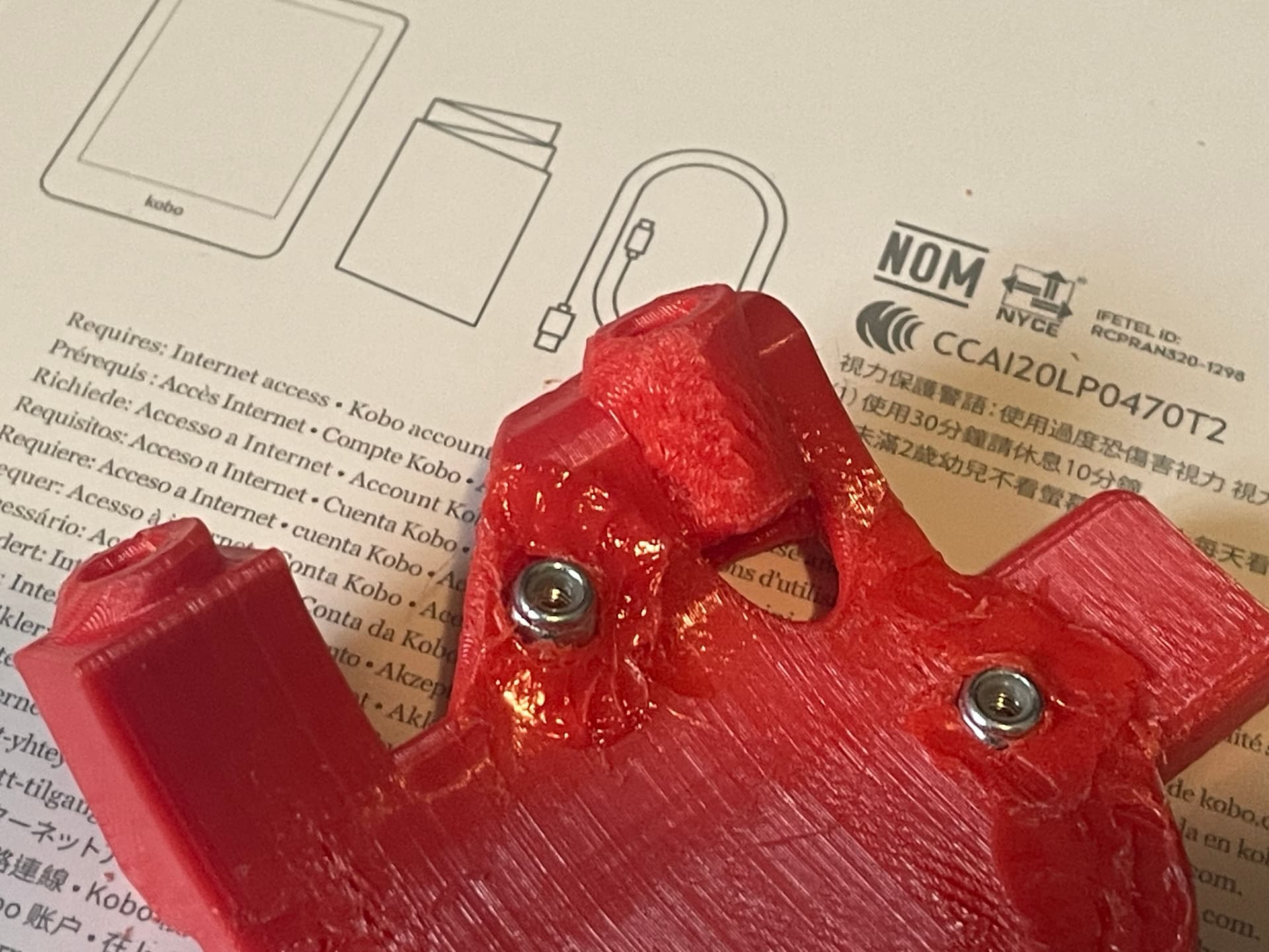
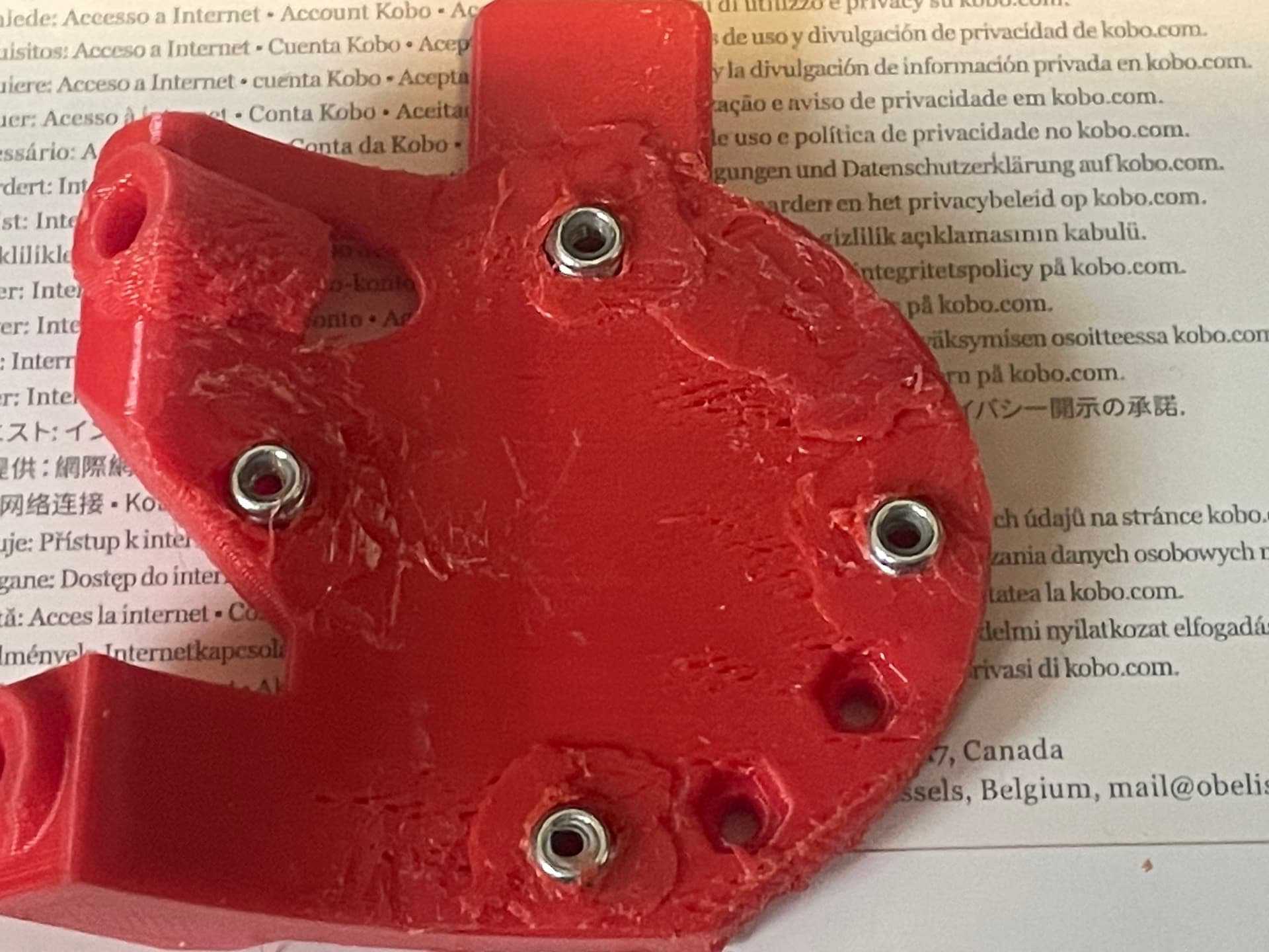
I found that using only three screws resulted in a bit of flex at the 3 o:clock position, so I drilled a hole and used the soldering iron to flatten a screw recess. (M3 x 30,mm)
I also added some extra PLA around all of the nuts to keep them securely in place (one or two of them kept falling out, even though they were very tight going in).
The holes in the mobile and fixed (B & C) “mountain and valley” parts were way too small to fit an M3 screw through without cracking the print, so I reamed/drilled all of the holes with a 7/64 drill bit, and the M3s fit (still snug, but easy to thread through).
The M3 x 16 screws mentioned somewhere above were too short to connect the Air Mist Mount to the Mobile (C) part, and were even a bit short for connecting the base (A) to the fixed (B) part. M3 x 20 for the Base/A and 20-25mm for the B/C are needed. Unfortunately on my second trip to the supply store, I grabbed a bunch of parts that were in the 20mm bin, and when I got them home they were all 16mm, so I need to wait until the place opens again on Monday and exchange them for the right ones. So the assembly is on hold at the moment.
I will note that the Side B version will allow you to mount the air mist chassis on either side of the print. I used the “opposite” or left side, and there is plenty of clearance.
I think that mounting it on the “normal” or right side would probably still clear the YZ plate, but for sure the “Front” version would have some interference issues
Wow, so sorry for all the issues you ran into. Getting tight tolerances on small nuts is challenging, because if you make it loose enough to insert the nuts without heat-serting them, then its easy for them to strip and spin. Heat-serting is easier with non-nylock kind. Also, tolerances can vary greatly depending on whether a printer is over-extruding, under-extruding, or perfectly-extruding.
Heat-serting by pressing solder iron against the nuts, gets the heat where it’s needed better so it does not deform the part real badly.
No apologies needed. A bit of trial and error is expected, and the parts are by and large very well thought out! Printer tolerances being what they are, some issues with sizes are not unexpected. Your idea of heat setting with the soldering iron is a good one, but maybe not the best solution using nylocs (as you mentioned).
I would wonder if remixing to include a screw hole at the 3 o":clock position might be a useful addition for future users.
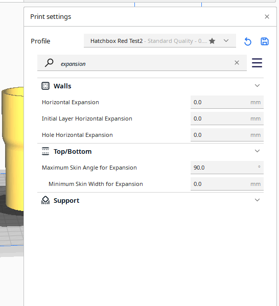
I hate to ask this but, did you run an Inside/Outside horizontal expansion test on your printer? When I recently was having problems with parts not having the correct dimensions I discovered that somehow my expansion setting had changed in the slicer. After I corrected the values everything fit much better.
It’s amazing how much a quick tweak restored the part’s functionality.
I did notice on a recent print that while the the outside of a cylindrical print is within 0.1 mm (46.12 on a 46 mm diameter), the inside of the cylinder is smaller and off by a bigger amount (40.55 on a 41 mm hole). Maybe I need to research the “hole expansion” setting a bit.
But I’m not sure the issues I had with the recess for the nuts is an issue with the printer tolerances, or if it was a matter of the nylocs possibly being larger than the print design. (something that I will have to check out).
Doug mentioned that the holes were designed to be pretty tight to ensure the nuts didn’t spin, so even a small amount of normal printer error could lead to interference fit and possible cracking.
I see you’re using some version of Cura. I also use that slicer and after doing a few tests I put as much as 0.125mm in one of those (can’t remember which one at the moment) and about 0.08 in the other. In Cura that is a value in the “Material” subsection and is likely to be different when you change filaments manufacturer or temperatures for the hotend or bed. Note that there is a separate value for first layer, which is there to offset “elephant’s foot”.
I’m definitely hoping to get a version modified for heat-serts out.
All printers vary in their degree of being able to print dimensionally accurate parts, and thus designing nut capture slots is a challenge.
That challenge magnifies whenever the nuts are small (M3).
This whole issue becomes even more fraught with potential frustration when the reason why capture slots are needed, is because they are for a blind reach, no access area because you cannot get any tool back in that tight recess.
I’m actually feeling the opposite of smug regarding my design choices here. LOL
Hello again, fellow makers. Today I caught a math mistake, and corrected the calculation of the X and Y offset when a Sharpie pen is in the holder (X and Y offset from center of cutting bit of LowRider to the center of the Sharpie pen).
Old, incorrect info:
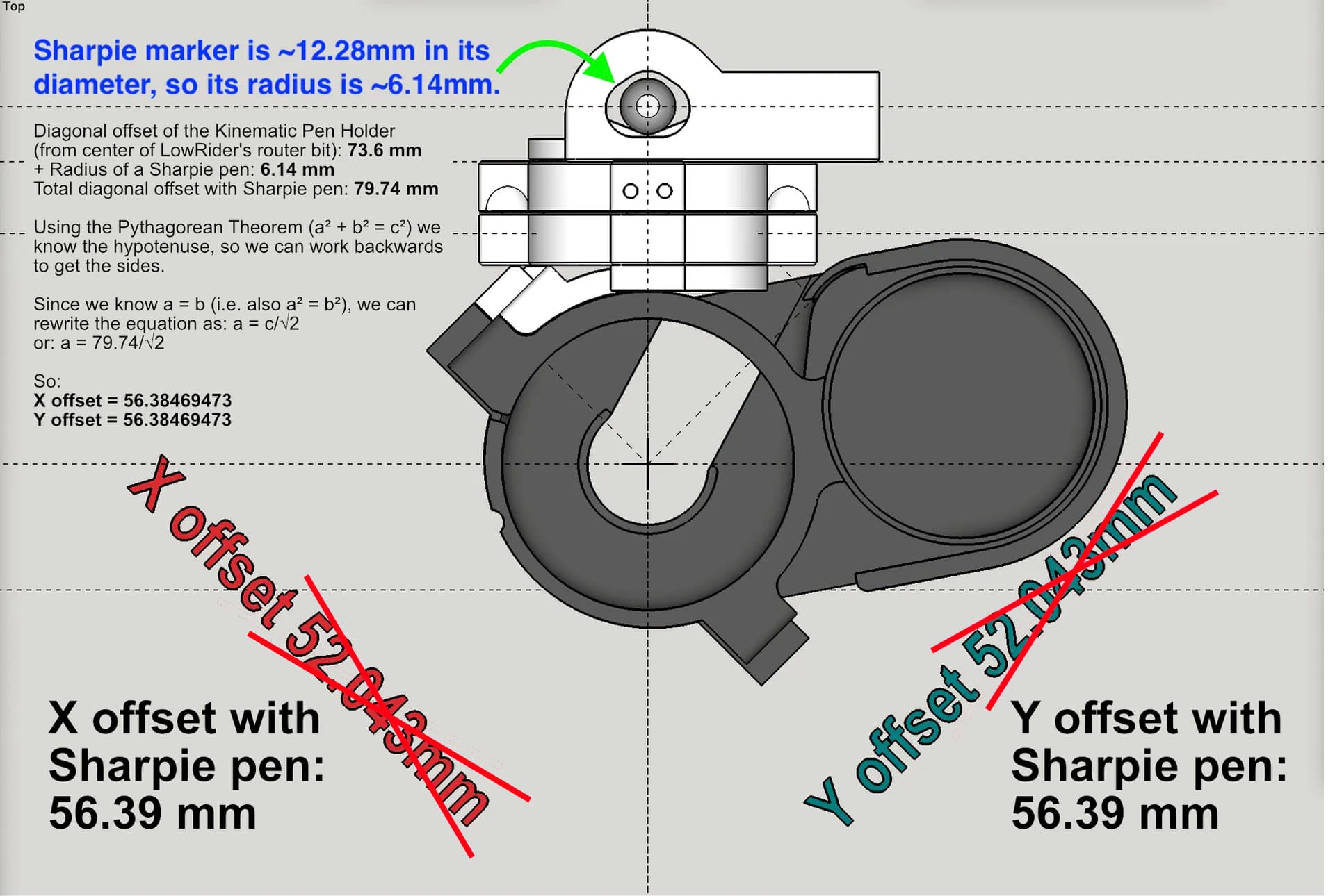
Here is the updated graphic with this info. I have also added it to the Printables listing.
Note: You can also use the same formula to calculate offset when your pen is a different diameter, or if you have altered the diagonal offset by use of washers/spacers, etc. Here’s how it’s calculated:
Diagonal offset of the Kinematic Pen Holder, when no pen is present (from center of LowRider’s router bit): 73.6 mm
(plus) + Radius of a Sharpie pen: 6.14 mm
Total diagonal offset with Sharpie pen: 79.74 mm
Using the Pythagorean Theorem (a² + b² = c²) we know the hypotenuse, so we can work backwards to get the sides. Since we know x offset and y offset are the same, i.e. a = b (i.e. also a² = b²), we can rewrite the equation as: a = c/√2
or: a = 79.74/√2
So: X offset = 56.38469473 Y offset = 56.38469473
PS: in a cell in a Microsoft Excel spreadsheet, the final formula is written as:
= 79.74/ SQRT(2)
I’ve gone through the thread and I couldn’t/didn’t spot a build for the new A40640 II laser. I printed the mount assuming the original is the same, no screw holes line up. I tried searching printables and came up with nothing that’s already been created. Has anyone made a A40640 II LR3 Kinematic mount?
If you search for that model name on printables and find something that is tailored for it, you can do a remix to make one. Also, perhaps there’s a diagram from the seller/manufacturer that tells screw hole schematic that could help in making a remix that fits it.