I think he’s planning for outside the mounts, beside the router, just aligned in X axis while staggered in Y axis.
Yep, I have no interest in removing my router.
I just want something that I can either leaver the laser permanently mounted, or a way to quickly mount the laser only when I need it.
I’m likely planning on getting the A40640, but haven’t made a final decision yet. Still some research to do.
I put the kinematic mount on it because I also have the drag knife and was hoping it was the right solution to be able to slide on either one when i need it.
Hopefully in the next month or so I’ll be ordering a laser
2 Likes
If you mount using the lower spindle clamp bolt and dust shoe bolt you can keep the diode square in XY (useful if you have a targeting cross) and at a known offset in X and Y, about 86mm and -63mm respectively. You don’t lose any usable area for your router mounting it this way.
New core? Is that a thing?
I’ve experienced the same wiggle as you did, and I was wondering if maybe fixing the base of the mount to the router mount behind it would be a solution, so it removes the cantilever and the lever action of the inertia of the laser.
I’ll try with a wood screw (the same that fixes the magnet in place) and I’ll run some tests.
1 Like
Not yet, but Ryan’s been ruminating on it.
1 Like
uhhh exciting, @vicious1 sign me up for testing if possible!
1 Like

So this is the solution that I’m going o try out. It will mount with 2 long zip ties to the router body, in between the two tool mounts, and I’ll be able to mount the magnetic base to this. I believe this will be more rigid than the current mount. Not sure when I’ll be able to remove the existing mount and install this… but it’s on the printer now. no I just need to go buy some 250mm long zip ties to mount it.
1 Like
Cool! Thanks for keeping us updated! That’s quite the remix!
Can’t call it a 100% success just yet. For some reason I had the wrong distance between supports for the LR3 core, and the space to fit the piece is 3mm too narrow.
I zip tied it to the router below the ring, only one zip tie, so still not really rigid…
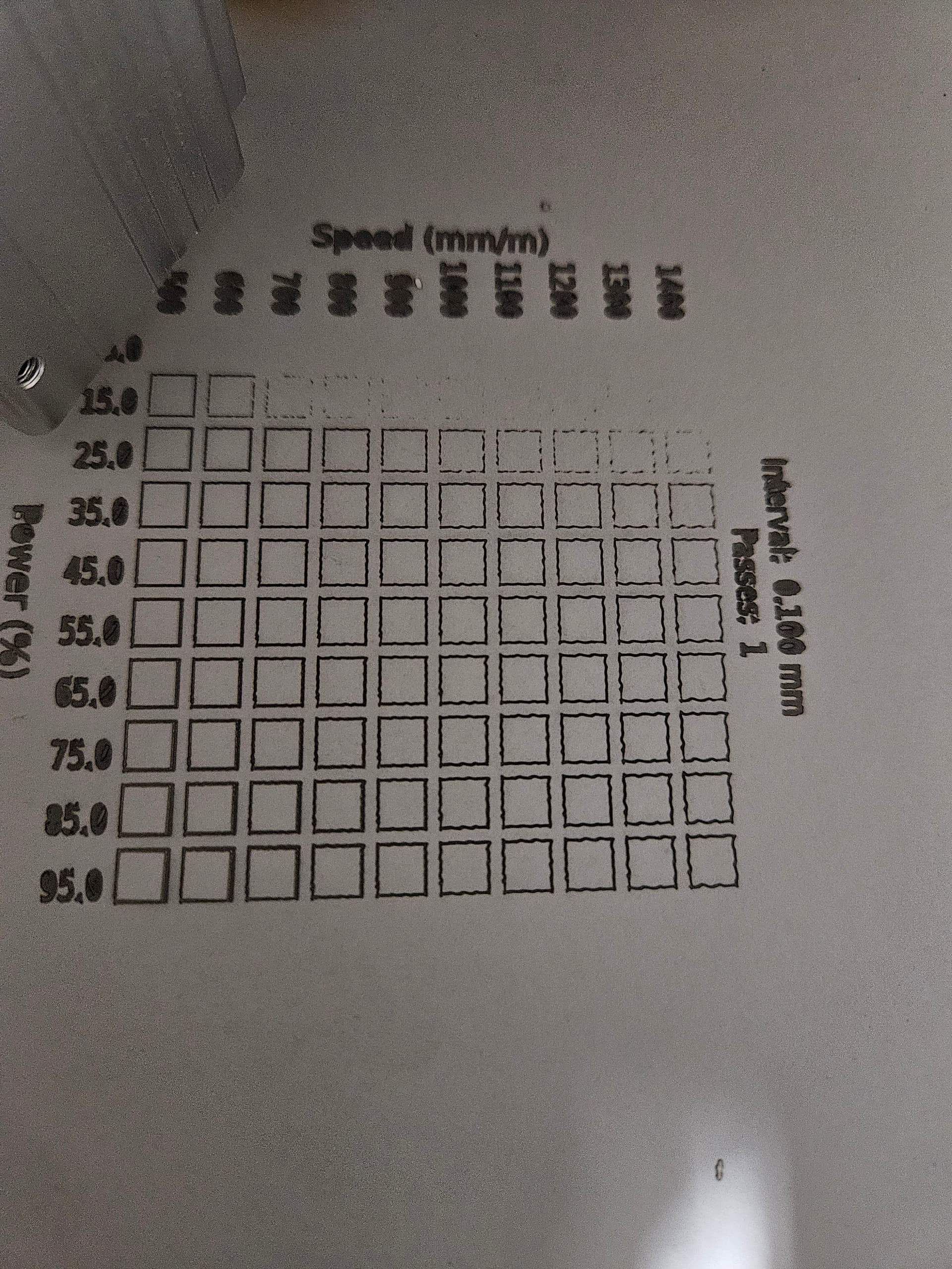
Note huge improvement in the text, and here I would call 1200mm/minute acceptable. Exact same gcode file on the same material.
I also decided that I don’t really need all 12 holes in there. It makes for some awkward bridging inside the zip tie holes, so…
Edit: looked back, and it’s about the same as the improvement after zip tying the old mount to the dust shoe, I guess, but with only the one tie holding it and no full contact with the router body (Because it was at the bottom of the router body) I think it’s promising.

I’ll give this a try today.
2 Likes
Nice!
Cool!
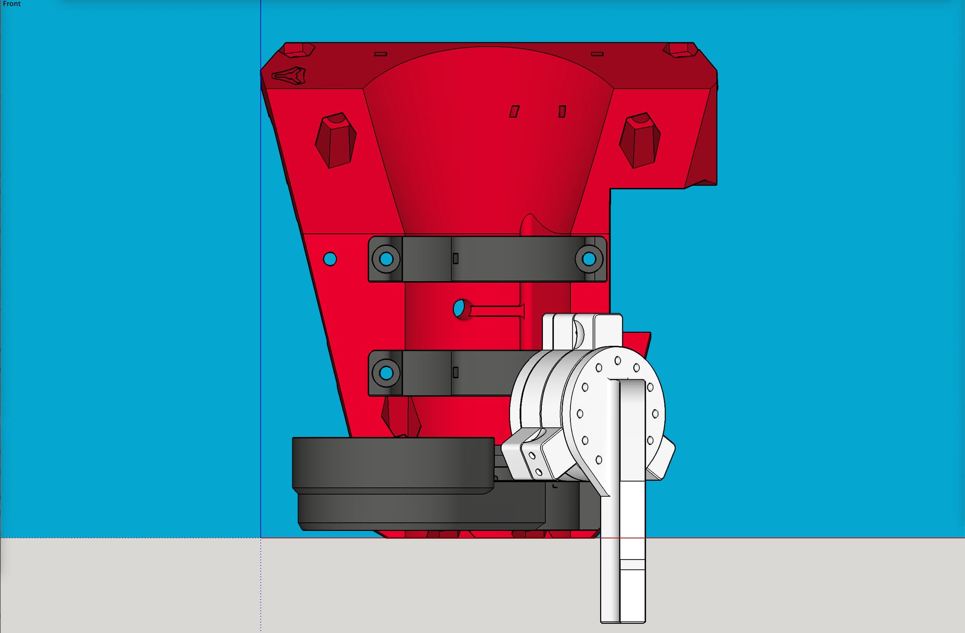
I’m looking at the pictures of the remixed air mist mounts, and it seems that all of them stick out past the core on the X Max side. Has anyone experienced the mount or the mist valve body contacting the YZ plate when the core is at the X Max position, or am I worrying for no reason?
There is both good news here, and not so good news. There are two flavors of the remix: one that does its 45 degree bend toward the front, and another that does its bend to the side. This image shows both:
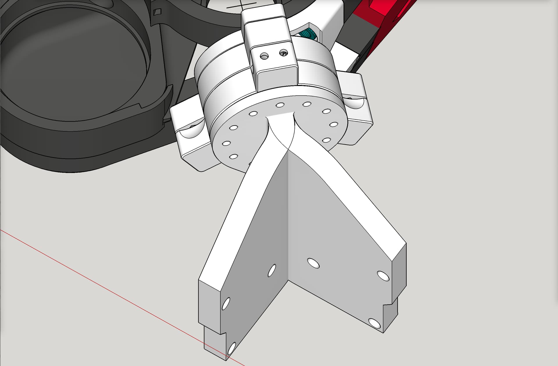
As you already noticed, the one that bends to the side, does go out past the side of the core:

However, the one that bends to the front, does not:
1 Like
can you share the model files? I’d love to try them as i’ve been having the same issue
As far as I know, all the files shown are published on Printables, and the links are listed in this thread.
Have you tried searching my Printables account for models having “kinematic” in the name?
As a help, here is a link that does that.
https://www.printables.com/@DougJosephdesign8stu/models?query=kine
1 Like
oh i was specifically refering to @SupraGuy mod
1 Like
ZipTie Mount.zip (196.5 KB)
This one worked for me. It was designed for the Kobalt router, but should work OK with the Makita as well
1 Like
Thanks for the CAD drawings. That helps a lot.
The A version of the front model still seems like the valve body would impact the YZ plate, but I’ll try the B version and mount the body on the opposite side.
1 Like
Just to confuse things a bit, the model that bends to the side is the Front version, and the model that bends to the front is the Side version. I’ll print the Side version B, so the printed part is further away from the YZ plate, and I can mount the valve body on the X Min side of the printed part to increase the clearance if needed. Photos within a day or three…
1 Like