Here’s the video I made about this!

Ok, as discussed over here, here is a link to where I posted the new KINEMATIC tool mount, tool-less quick change accessory holder.
Download: Printables
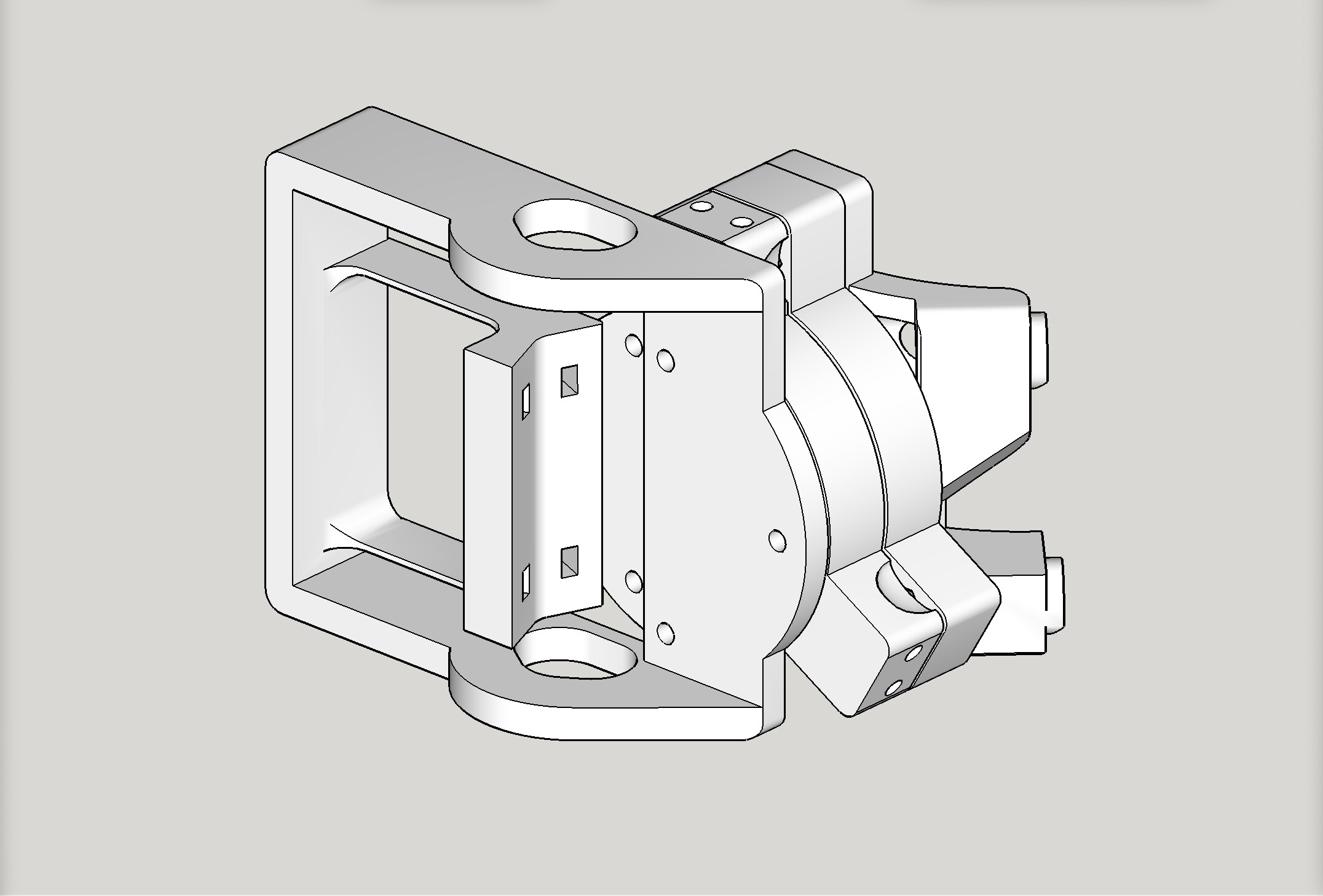
This is an adaptation of a Maxwell Kinematic coupling. You can read about that here: Kinematic coupling - Wikipedia
Original motivation was a nudge from Jamie K on the V1 Engineering forum.
Speaking of which, Jamie has now remixed this in a way that requires no acorn nuts, no screws for troughs, only one magnet on one side, no need for drilling any magnets for additional countersinking, and no need for prying any magnets out for flipping them. Check out his remix here. His remix avoids acorn nuts and avoids troughs made from screws, all by having both “mounds” and “valleys” made from 3D printed plastic. Here’s a photo of Jamie’s remix:
Additional inspiration for my work here came from Workshop Feedback channel’s posting of his custom CoreXY printer and it’s electromagnetic tool-changer. My design is a freshly created thing from the ground up, and I don’t at this point utilize his concept of having flexible printed mounts for the magnets, but I drew heavily on his excellent work on his tool changer.
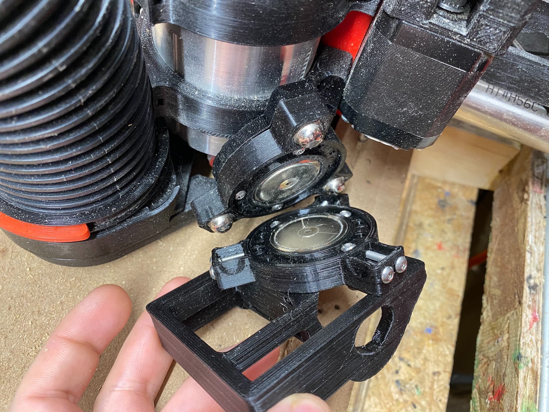
Summary of Kinematic coupling: “fixtures designed to exactly constrain the part in question, providing precision and certainty of location.… consists of three radial v-grooves in one part that mate with three hemispheres in another part. Each hemisphere has two contact points for a total of six contact points, enough to constrain all six of the part’s degrees of freedom.”
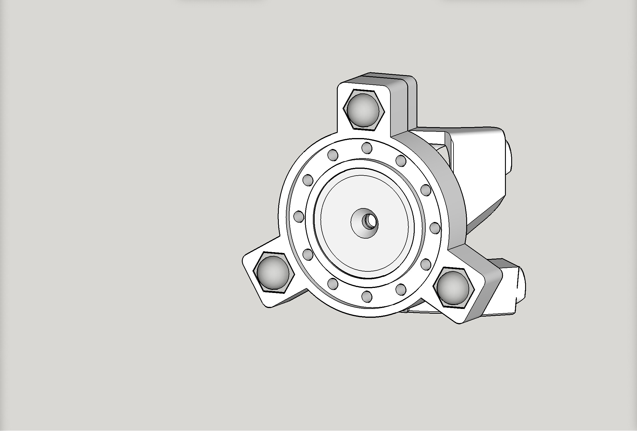
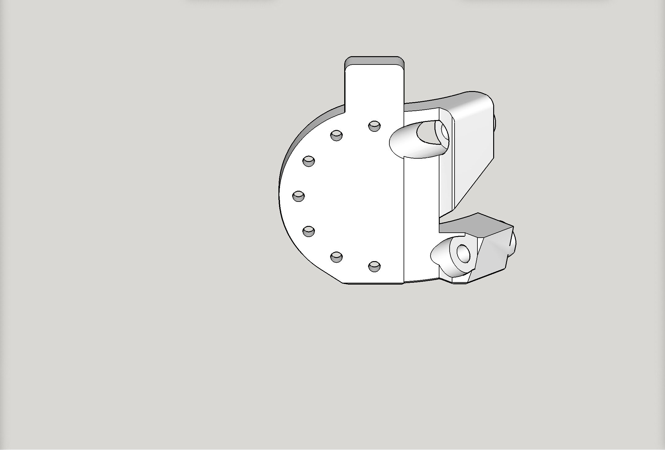
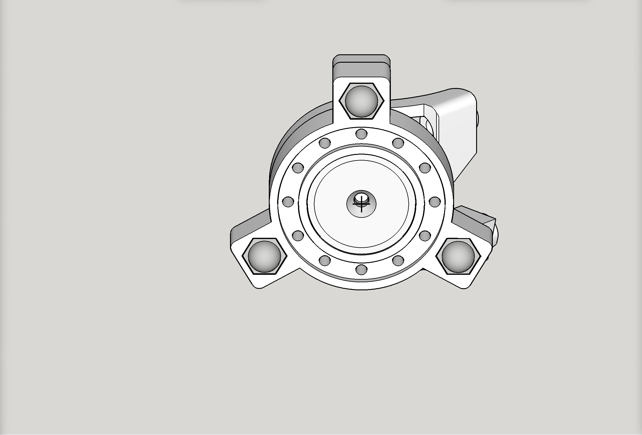
In this case, I’m combining use of disk magnets for the coupling force, common M3 x 16mm screws arranged in a 3D-printed “mobile base” to form the “three radial v-grooves”, and common ¼"-20 acorn nuts (aka cap nuts) arranged in an opposing 3D-printed “fixed base” to serve as the “three hemispheres” and thus is achieved an easy, affordable Maxwell Kinematic coupling.
Note: I will link to separate Printables listings for various specific tool holders, intended to serve for attachments. I’ve already created for this: a NEJE diode laser module holder, a drag knife holder, and two pen holders, which are remixes of prior remixes (with the most recent being an “inverted” one by Jamie, @ jamiek on the V1 Engineering forum, which served for my first tool holder for this new accessory quick-change mount system).
This system affords a one-to-many relationship between a “fixed” side (you need one set of it) and as many “mobile” side sets as you want, interchangeable.
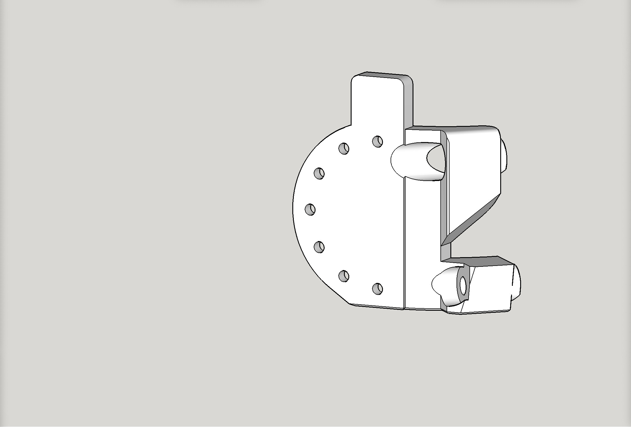
- The “fixed” side is comprised of two parts:
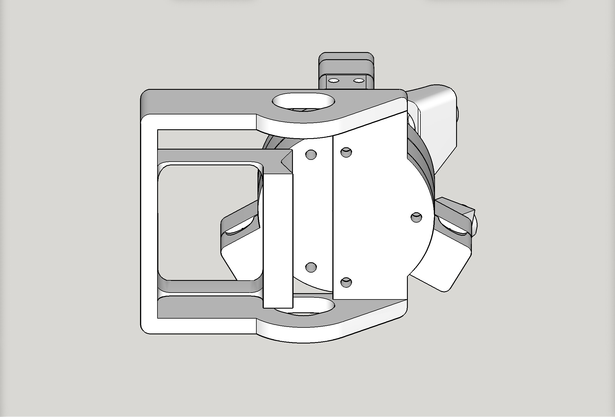
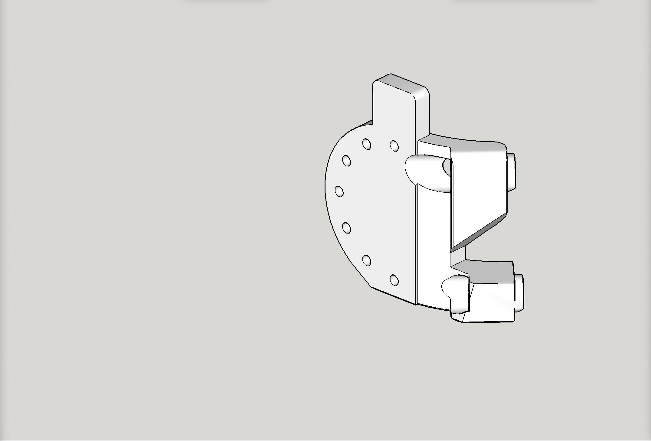
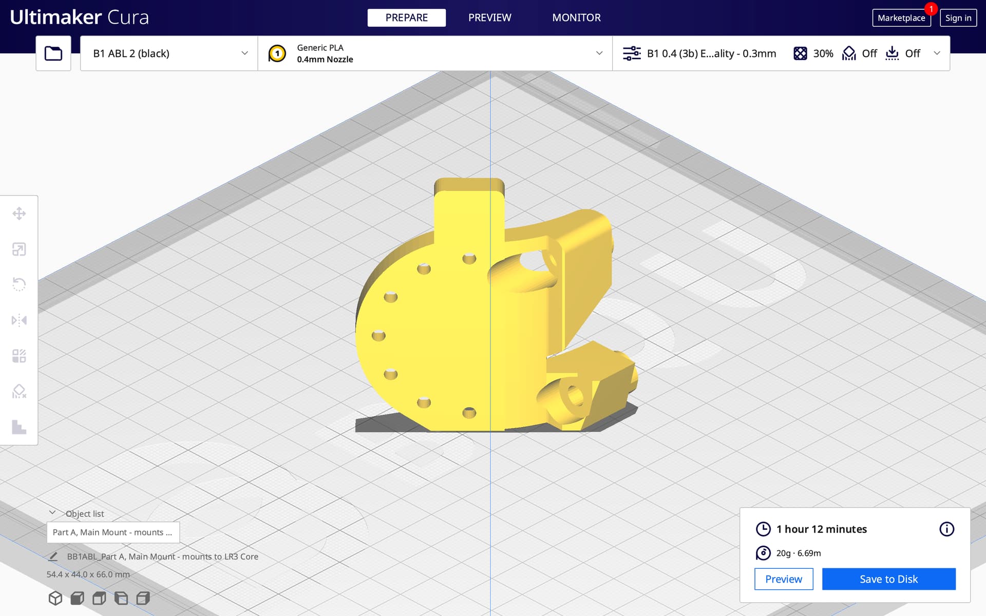
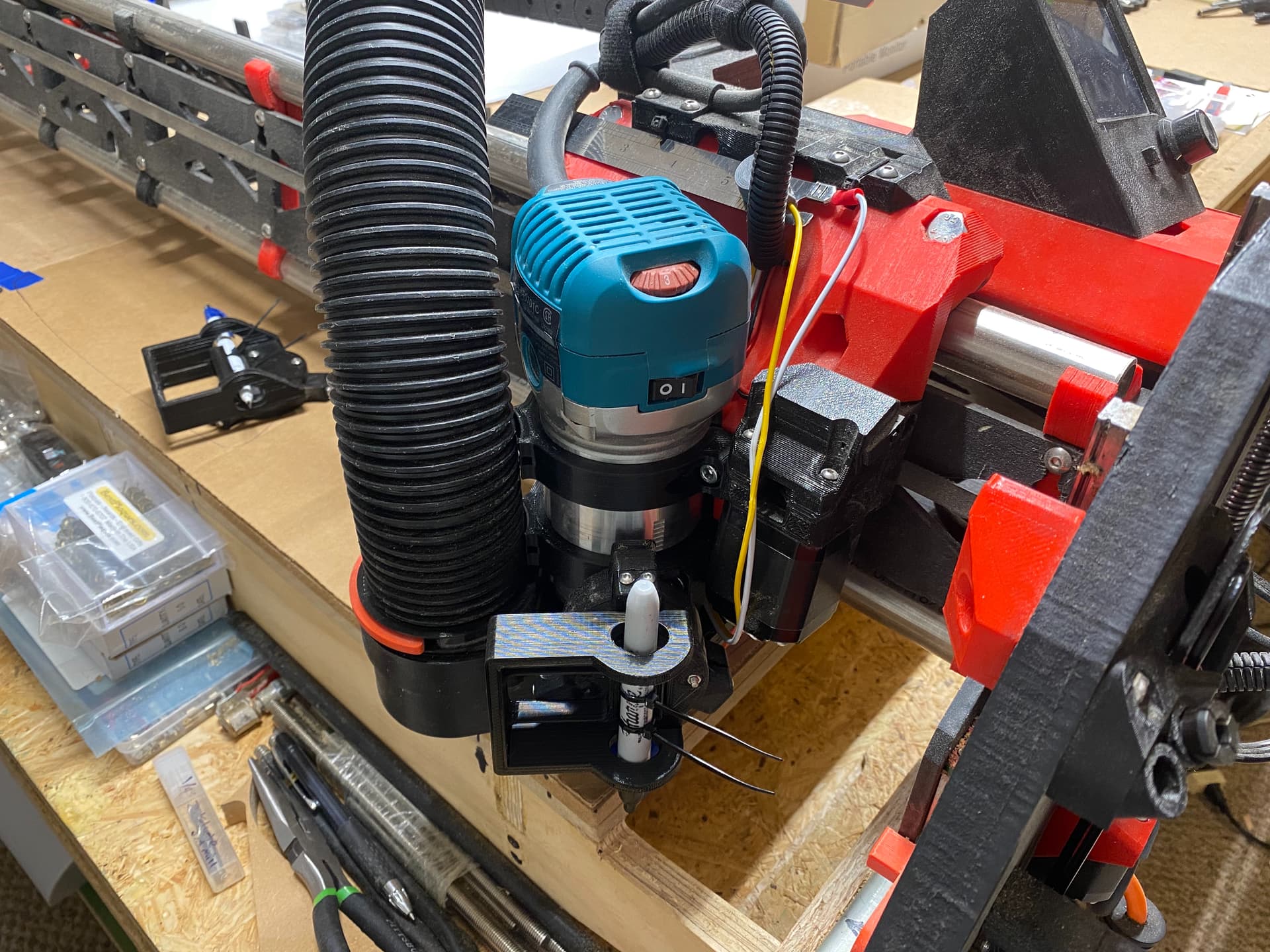
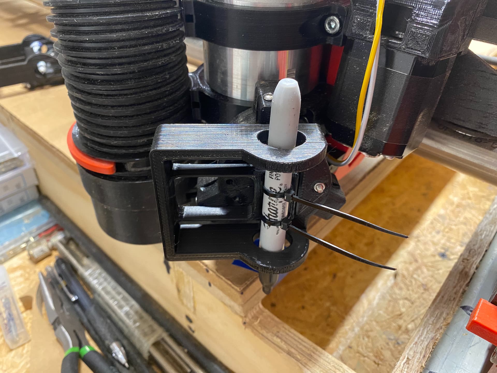
- new Main Mount that is merely a new iteration of my previous pen-mount / tool-changer designs, which gets attached to a LowRider v3 using two (2) M5 x 45mm screws), and
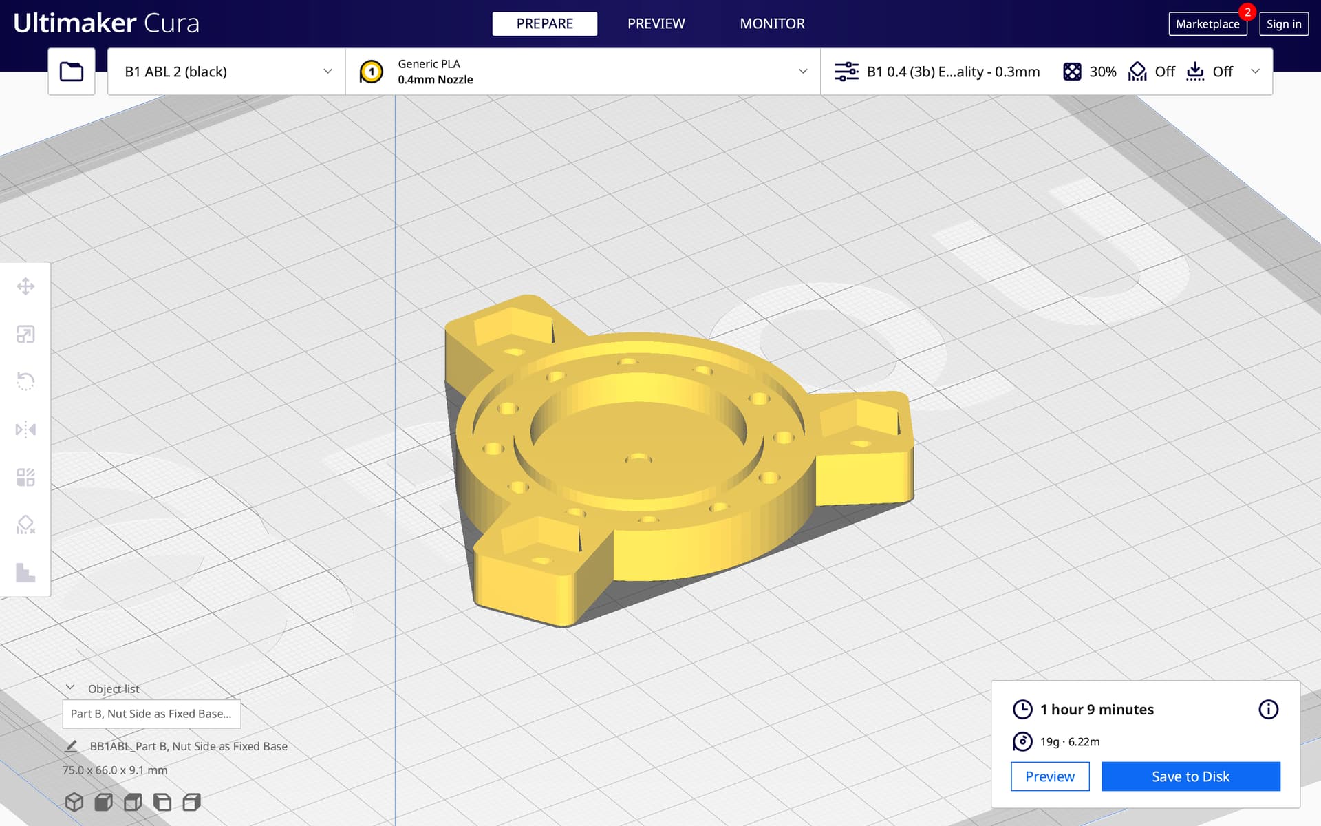
- new Fixed Base that gets attached to the Main Mount using at least three (3) M3 x 16mm screws. The Fixed Base has one of two disk magnets.
- The “mobile” side is comprised of two other parts:
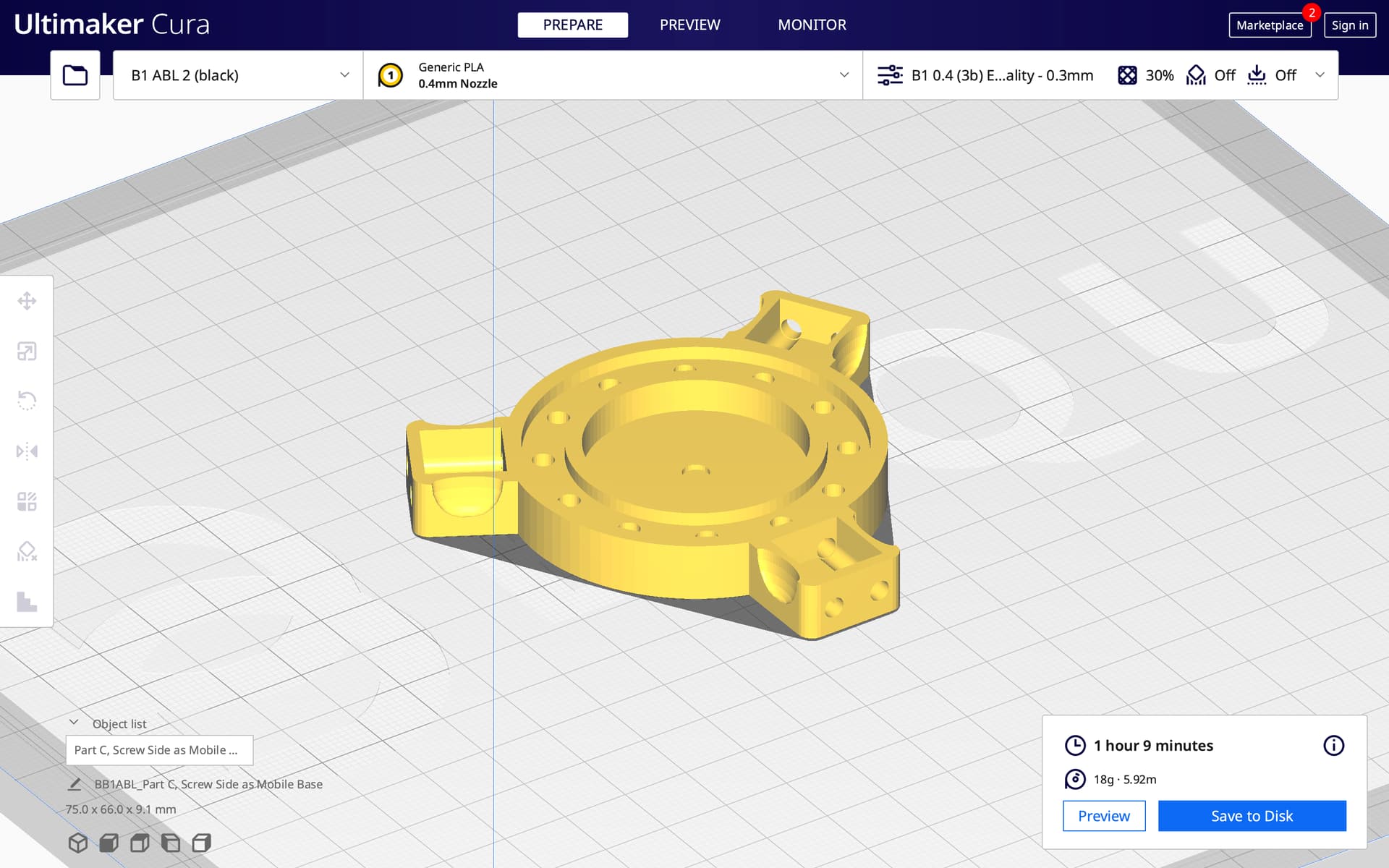
- new Mobile Base that gets a specific tool holder attachment on one side, and which has the second of two disk magnets in it on the other side, allowing it to be magnetically bonded to the Fixed Base, for what we hope is a suitably strong hold for using add-on tools.
- A specific add-on tool holder, for items such as pens for plotting/drawing, drag knives for cutting vinyl signage, and diode lasers, while other possibilities include a depth finder I’ve been pondering conjuring for a while that would be a bit like a BLTouch, except for LowRider CNC work.
Aside from the two M5 x 45 screws, and two tapered head M4 x 10mm screws and nuts (or M4 x 12mm, depending on your situation), so far pretty much everywhere else I’m using M3 x 16 mm screws (and nuts), and M3 x 12mm screws (and nuts). The M4 screws are serving to hold the magnets in the bases, and thus are optional as you could opt for epoxy glue instead.
The magnetic force of attraction is adjustable, and ranges from adequate to overkill. When the length of an attached toolholder / tool comes into play, then that adds leverage, which helps with the task of separating the coupling halves, when desired.
Note: since acorn nuts can vary from brand to brand, not all 1/4"-20 acorn nuts are the same height. This can be accounted for by measuring, editing a parameter in Fusion 360, and reprinting the Fixed Base as needed.
I have two brands of acorn nut that are vastly different. One has its “dome” approximately 2.7mm taller than the other brand. This added height makes a huge difference. Unless compensated for, the magnets are too far apart to be effective. The workaround is to edit the “Fixed Base” component and deepen the capture wells that hold the acorn nuts. In this way you can tailor your Fixed Base to the acorn nuts you have available. I have uploaded both a Fusion 360 file and a STEP file to make it easier to remix/tailor to your needs. To edit this depth, in Fusion 360, in Design mode, click Modify > Change Parameters, and then edit the value of the “Depth_of_acorn_well” parameter. After editing, you can right-click on any affected components, in this case “Part B, Nut Side as Fixed Base” and choose “Save As Mesh.”
PRINT INFO:
- Print as oriented.
- Prints with no supports needed.
- Use the same number of perimeter walls and same infill as most of the LowRider 3 parts.
BOM:
- Filament of your choice (I’m using PLA)
- These disk magnets: https://amzn.to/43slRo7
- Three (3) of these ¼"-20 acorn nuts: https://www.lowes.com/pd/Hillman-3-Count-1-4-in-Nickel-Standard-SAE-Cap-Nuts/3035978 (Or if you want to have a stash: Amazon.com - but see the note above about the differences between brands. The Amazon listing is the one that is about 2.7mm taller than the Hillman brand from Lowe’s.)
- Two M5 x 45 mm screws (from my stash but like these): https://amzn.to/3Wgltqa
- Two M4 x 10mm / 12mm screws & nuts from this assortment: Amazon.com
- 12 or more M3 x 16mm screws & nuts from this assortment: https://amzn.to/3OoX53Y
COMPATIBLE TOOL HOLDERS:
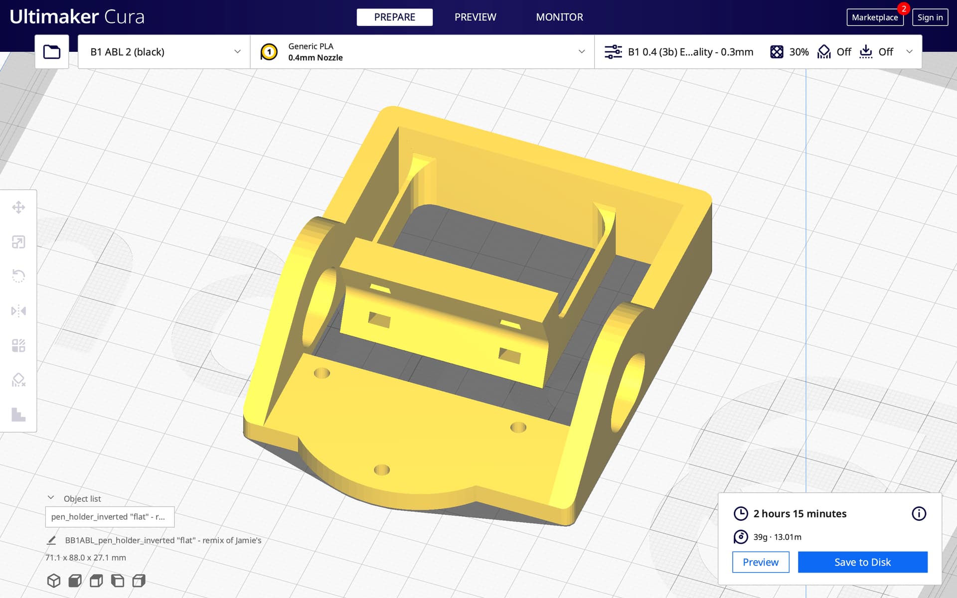
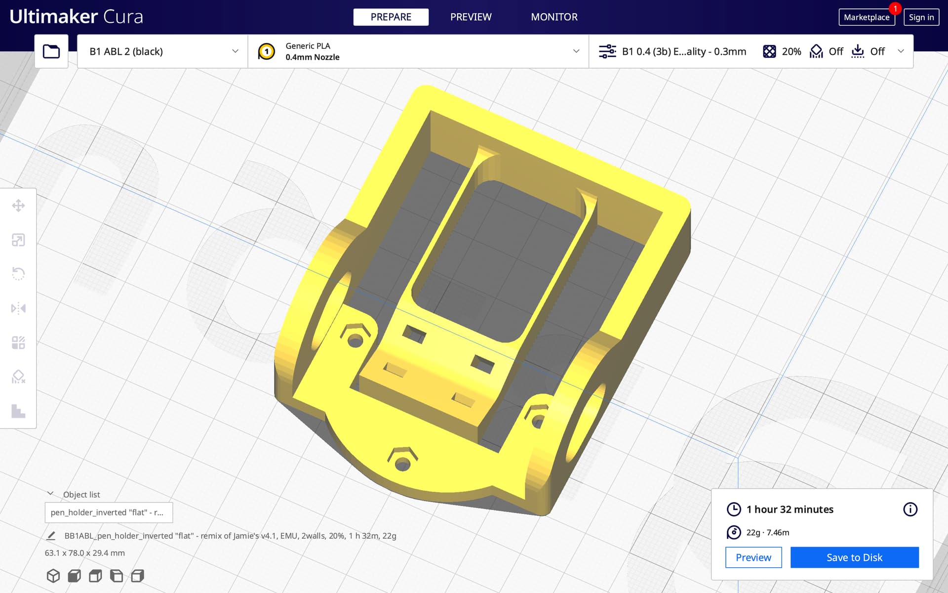
- Pen Holder Inverted, remix of Jamie’s inverted pen holder: Printables
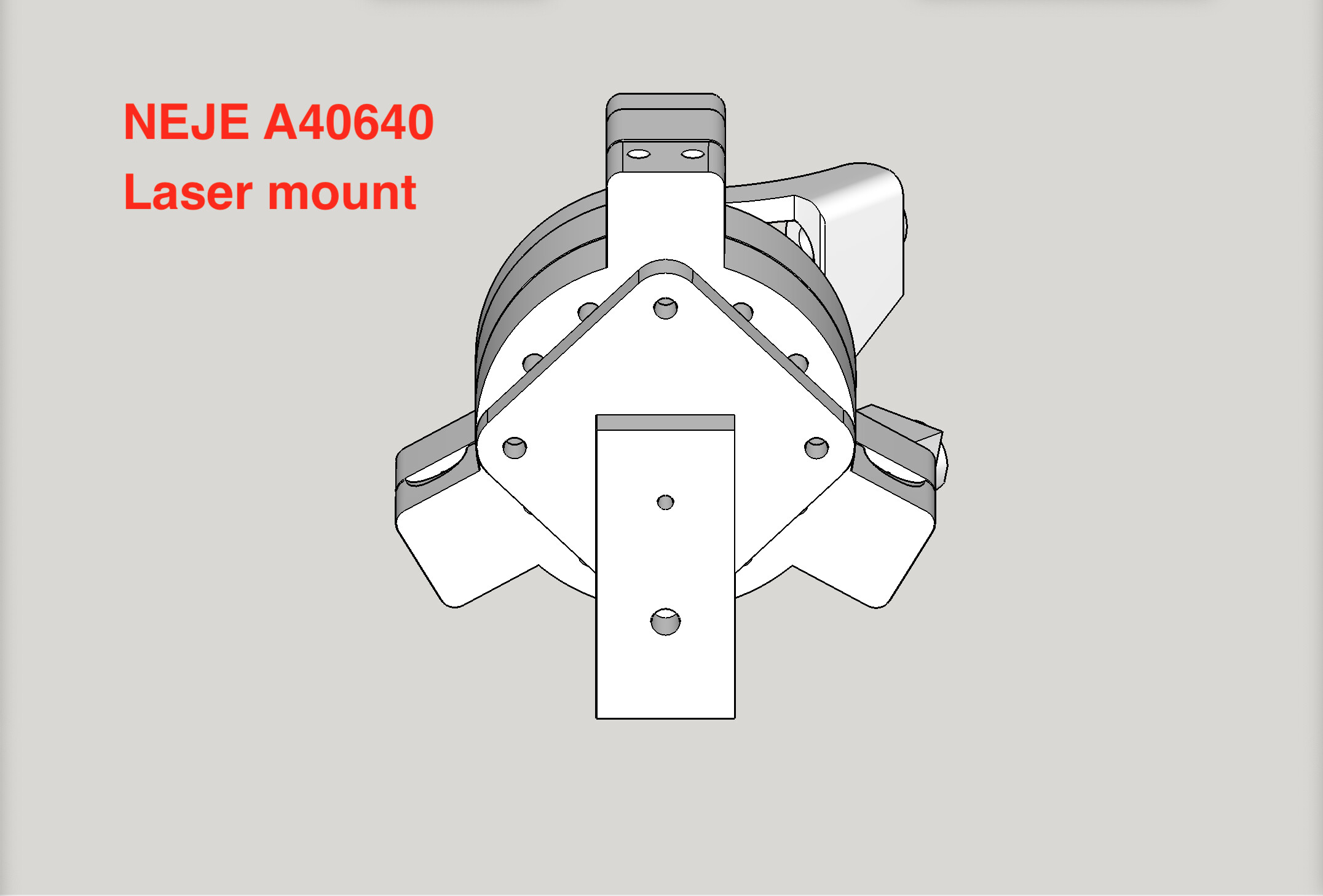
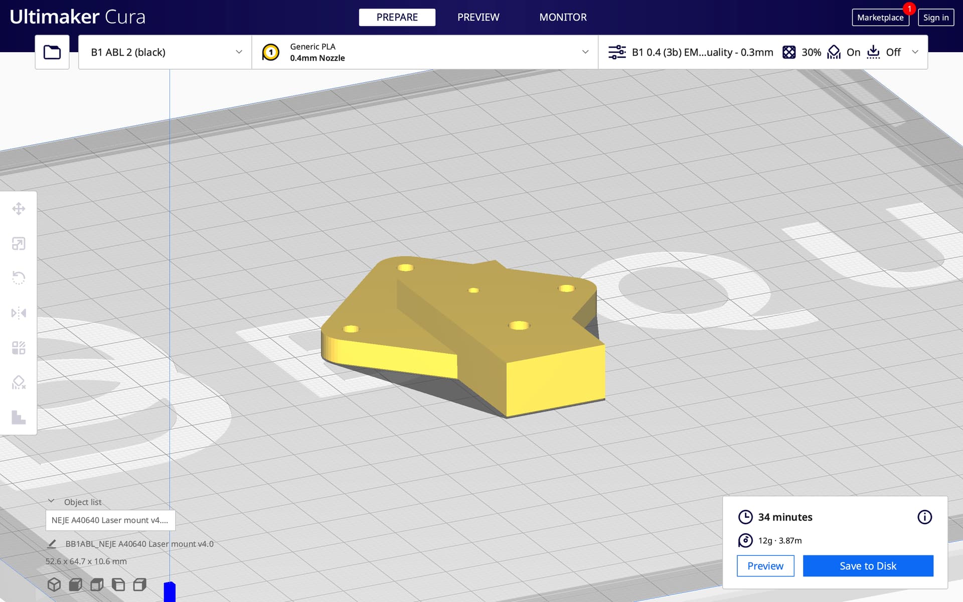
- Laser mount for NEJE A40640 Diode Laser: Printables
- Pen Holder, not inverted, v4.0 - generic design for pens on LR3 Dust Shoe, made for this v4.0 kinematic system: Printables
- Drag Knife Holder v4.0 - 1.0mm spring leaf (for drag knife such as sold by V1 Engineering): Printables
BUILD STEPS & NOTES:
- Print all the parts.
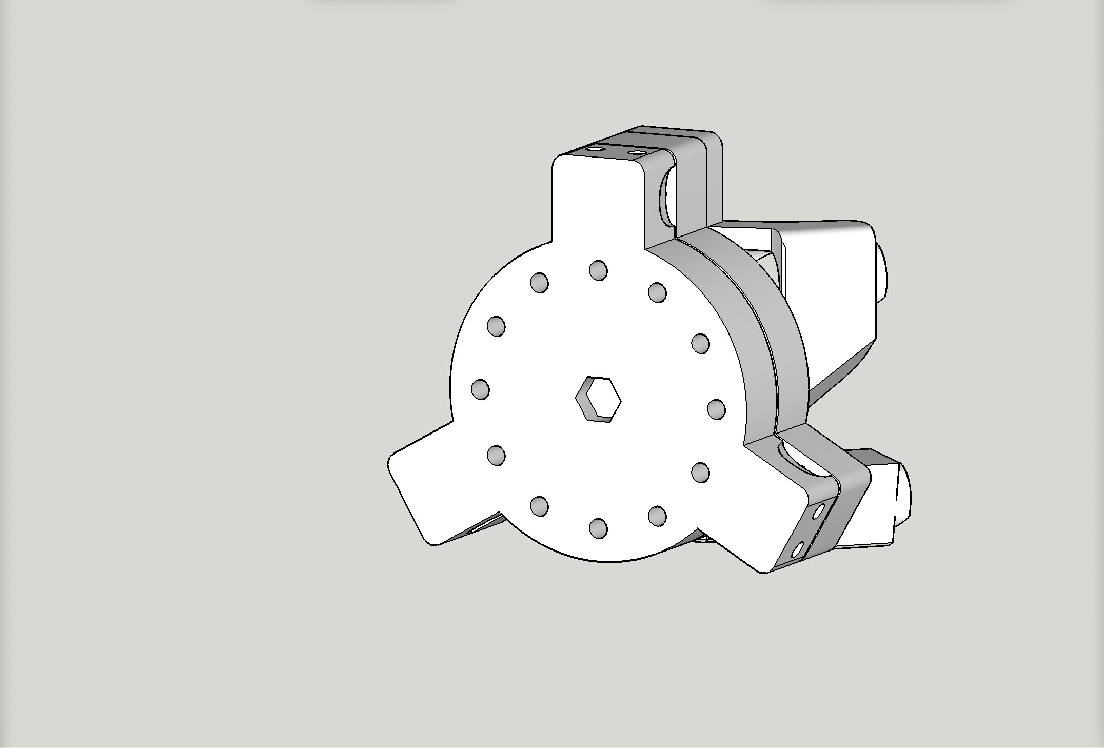
- Insert three (3) nuts, M3, into three of the nut capture slots on the back side of the Main Mount. I chose to use the holes at 12 o’clock, 6 o’clock, and 9 o’clock. I left other holes just to allow for future possibilities not even on the radar. The upward protrusion on the main mount signals which hole is 12 o’clock.
- Use of pliers can help with squeezing the nuts into the capture slots. Optionally you can insert screws through from the front, and tighten them until the nuts get pulled into the slots. It’s important for the nuts to be properly oriented for a straight approach by the screws, later, when attaching the Fixed Base.
- If you plan to use epoxy or some other glue to hold the disk magnets in the Fixed Base and Mobile Base, you can skip this step. Otherwise, for use of M4 screws to hold the magnets in place, insert two (2) nuts, M4, into the back sides of the Fixed Base and Mobile Base. Use an M4 screw, inserted from the front, to tighten until the nuts are in place. Remove the M4 screws for now.
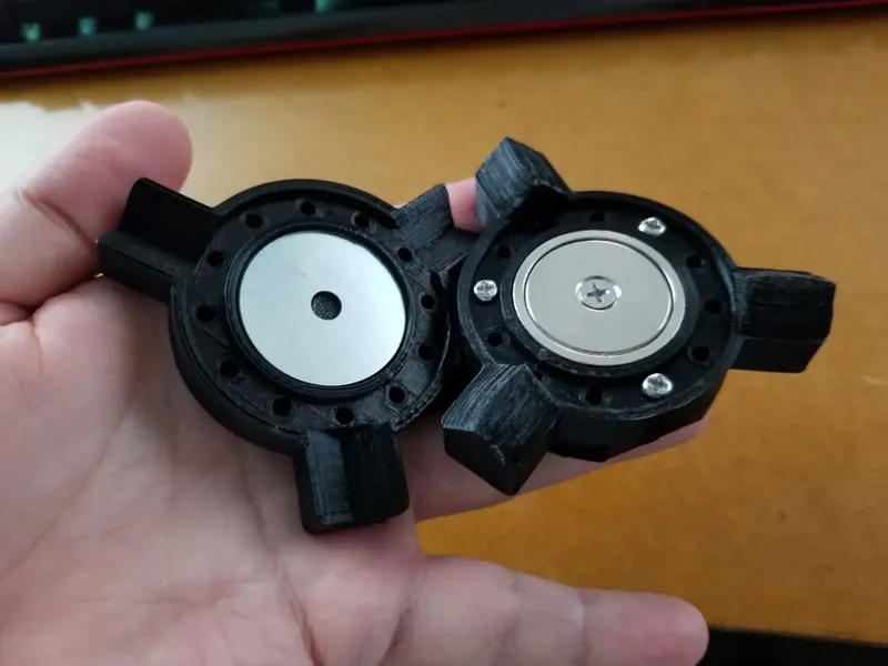
- Install the disk magnets into the Fixed Base and Mobile Base.
- NOTE: The two disk magnets have to face in a way that attracts. Based on how the magnetic field is flowing in the strong magnets I sourced, this seems to always mean either that one of them has to be “fillet up” (metal cup facing out) while the other is “fillet down,” or else that you have to pry out one of the magnets from its metal cup, and flip it over and reinstall it (and counter bore its side now facing out). If you choose to flip one as “fillet up” then either it has to be glued in, or else the screw hole will need a counterbore area opened up in the metal cup so the M4 screw can be counter sunk. If you choose to pry out and flip, then be aware that neodymium magnets are brittle. It’s easy to break them. However, I broke some and still used them. They are squeezed in between the screw lip and the edge of the metal cup, and they stay in place. Also, their brittleness can become apparent if you screw them down too tightly, or if you use too much clamping force in pushing them into position. The metal of the magnet is both hard and brittle. I found that attempting to drill out a counterbore hole in the magnet itself, was a futile effort given my available tools.
- NOTE: In order for the kinematic coupling to work, the spheres, in this case the caps of the acorn nuts, must all make firm contact with the M3 screw troughs before anything else touches. Also, in order for the magnets to provide enough coupling force, the magnets must be almost touching, aka practically touching, by the time the acorn nuts get seated into place against the M3 screws. This means the M4 screws need to be totally flush, not proud at all. You may need to pre-grind the top of a screw off, if it’s sitting proud.
- Install three (3) acorn nuts (¼"-20) into the three capture slots on the “star points” of the Fixed Base. I found it easiest to hold them straight with pliers, with their hexagonal bottoms positioned for straight entry, and then press them into the opening. Once they are “started” in, they can be tapped in the rest of the way with a rubber mallet or dead blow hammer. Avoid use of a regular metal hammer, or you will flatten the tops of the acorn nuts.
- OPTIONAL: use of glue can ensure they don’t come out, but if you have a tight fit, it may not be needed. If you later need to remove them, say to move them to a new print, you can force them out by inserting something slender, like an allen key tool, through the holes on the bottom of each star point, and tap with a hammer.
- Install six (6) screws, M3 x 16mm, into the Mobile Base, two into each of the “star points.”
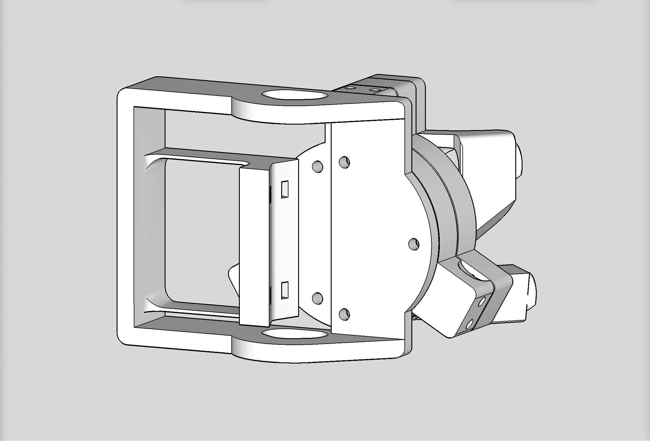
- On your LowRider v3: Remove two M5 screws — one from the right side of the lower router mount, and one from the right side of the dust shoe mount.
- Replace the above M5 screws with longer ones (recommend M5 x 45mm), inserting them though the Main Mount part, then back into their original locations. Tighten pretty snug.
- Attach the Fixed Base to the Main Mount using three (3) screws, M3 x 12mm. This corresponds to the above mentioned nuts at 12 o’clock, 6 o’clock, and 9 o’clock.
- Attach some specific printed tool holder of your choice to one of your prints of the Mobile Base, presumably with the tool.

- Magnetically click the Mobile Base onto the Fixed Base. Check alignment and grip. Test out use of the tool. Report back here in the comments!
Q&A:
- Q: What’s the purpose of the upward protrusion on the Main Mount?
- A: It’s sole purpose is to aid with assembly, by offering a visual cue for alignment of the Fixed Base
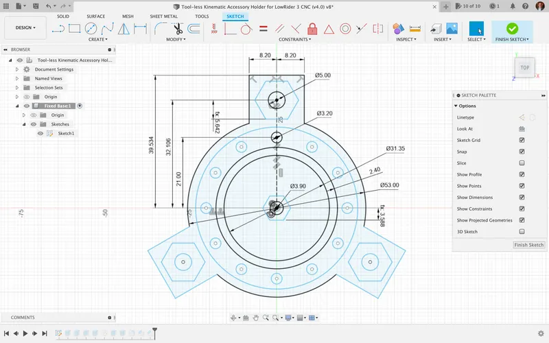
- Q: For making my own custom tool holder to be compatible with this, what do I need to know?
- A: There is an included file named “Blank for remixing mount for your tool holder.stl” that can be used to help you. Also, you can make your own blank by creating a “clock face” that is 53 mm in diameter, as thick as you need, and which has 12 screw holes (M3 size) positioned like the hours of a clock face, and at 21.0 mm radius from the center. This sketch from the Fusion 360 file shows some key dimensions:
UPDATES:
- June 9, 2023 — Regarding “Part A, Main Mount - mounts to LR3 Core” part being updated to v4.1: This new revision has a deeper screw well on the lower M5 mounting screw hole, to fix an issue of collision with Part B, which was caught and reported by fellow V1E maker Kris (**@**KL2001 on the V1 Engineering forum). Kudos to Kris. Thanks for the heads up. Also, watch for more new updates soon that will simplify making this tool mount, and the BOM for it.
- May 19, 2023 — added link for new tool holder, for NEJE A40640 Diode Laser
- May 18, 2023 — Quite a few design/print/test prototype iterations preceded this beta release. Video forthcoming. If I can get one hand free.
Change log:
- June 9, 2023 — updated the “Part A, Main Mount - mounts to LR3 Core” part to v4.1. See “Updates” above for details.
- May 23, 2023 — uploaded a slightly tweaked version of Main Mount, to get more perfect alignment of screw holes between Main Mount and Fixed Base. Changes were so tiny as to be barely measurable. No need to reprint if you already printed the Main Mount, unless you are having issues with using it.
- May 20, 2023 — rebuilt two components using Fusion 360 instead of SketchUp, both for precision as well as to make key aspects parametric, so users can tweak as needed. Uploaded these two new components as STL files, and provided both Fusion 360 archive and STEP file for easier editing/remixing.
- May 18, 2023 — initial release, in beta.
My PayPal tip jar: https://paypal.me/design8studio
Various LowRider 3 CNC remixes:
View all my models and remixes on Printables:
*Amazon product links are affiliate links.