Hi all, after getting a couple of issues resolved on the Marlin Github, there is now a Marlin build that supports an SKR 1.3 with dual y and z endstops in TMC2209 uart mode with sensorless homing. As of today, the fixes are in the bugfix-2.0.x branch. The relevant changes that need to be made to enable the options in the firmware are:
Configuration.h #define EXTRUDERS 0 // This enables remapping of E0 and E1 to Y2 and Z2
Configuration_adv.h #define SENSORLESS_HOMING // StallGuard capable drivers only
#define Y_DUAL_STEPPER_DRIVERS #define Y_DUAL_ENDSTOPS #define Y2_USE_ENDSTOP _XMAX_ //This is a change from default
#define NUM_Z_STEPPER_DRIVERS 2 #define Z_MULTI_ENDSTOPS #define Z2_USE_ENDSTOP _YMAX_ //This is a change from default
#define X_STALL_SENSITIVITY 20 // Stall sensitivity must be > 0 #define Y_STALL_SENSITIVITY 20 // Stall sensitivity must be > 0 #define Z_STALL_SENSITIVITY 20 // Stall sensitivity must be > 0
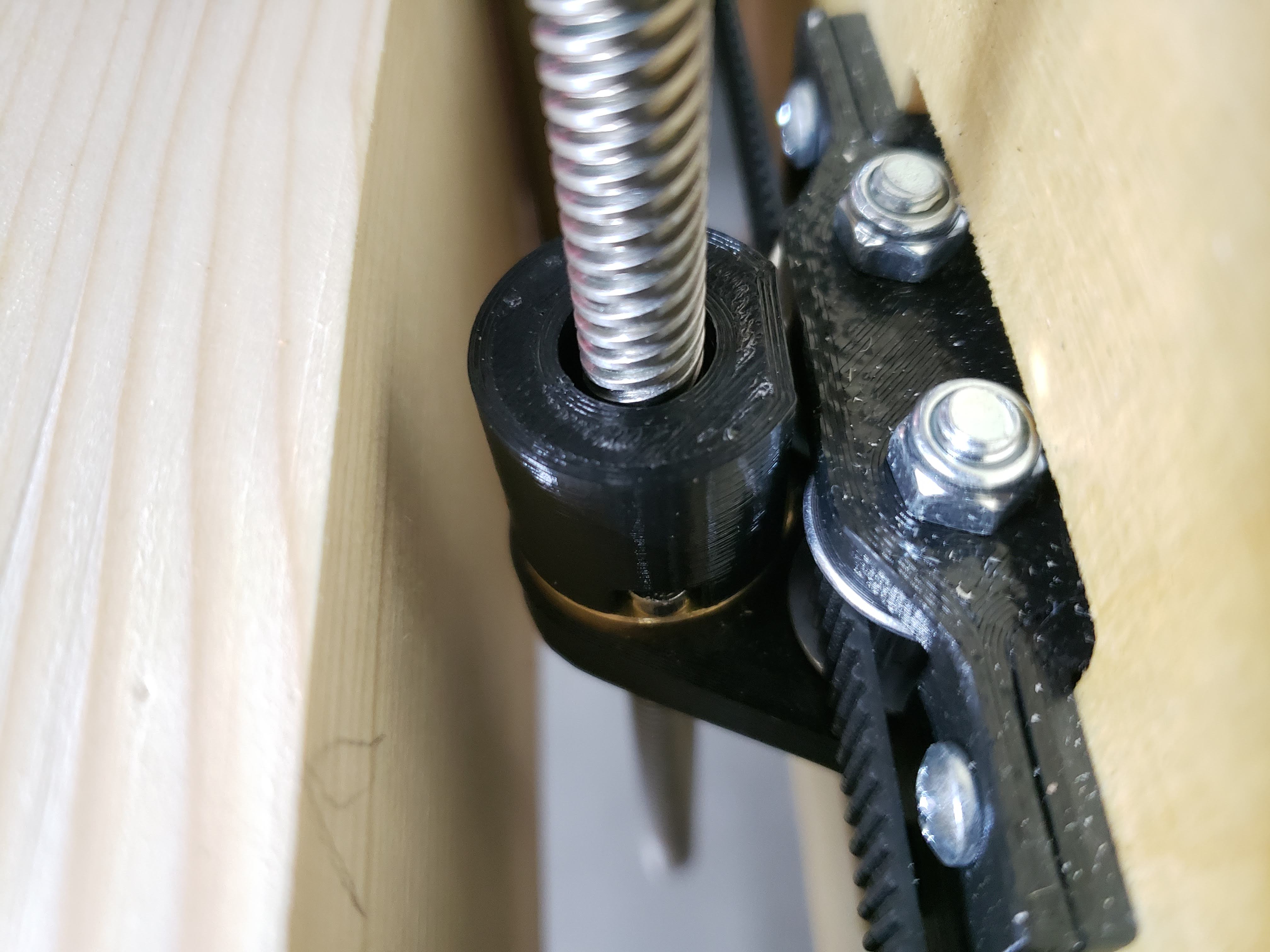
The above changes are for homing to Zmin. My build is now homing to Zmax. I put lock collars under the T8 rod which allows for a stop which is the same distance from the board for Z and Z2. There were some changes necessary to pins_BTT_SKR_V1_3.h
This line:
“#if Z_HOME_DIR > 0 && Z_STALL_SENSITIVITY && !defined(USE_ZMAX_PLUG)”
needed changed to
“#if Z_HOME_DIR > 0 && Z_STALL_SENSITIVITY”
I opened a bug on the Marlin GitHub. Hopefully a change will be incorporated into the next release for this.
I have collars below each of my z leadscrews. I home to z-max and have set the collars so that z1 and z2 hit the max at exactly the same distance from the table.
I like the idea of the collars, i was going to print clamps for the bottom of my pipes but this seems easier and more effective.
But, what I was wondering is if the setting for the Z homing is 0 when the router punges into the wood does it bind and cause the Z motor to stop or “home”. This is a new concept to me so I am not sure if I am over thinking it.
CNC is somewhat different from 3D printing. The home position is determined by where you want the operation to start, not necessarily as a set position as on a 3D printer. I have been using Fusion360, and depending on the operation, I sometimes set the home position at the base of the object I am milling, and sometimes at the top.
This topic has been covered several times in this forum. Take a look at this post: Setting home positions
You definitely don’t want the machine to slam into the microswitches with the weight of the gantry when off. I don’t have endstops on my LR, but if I was going to put them on the -position, this is what I’d do:
I’d put them really close to the bottom of the travel. The 611 plate needs clearance wherever I’m homing to reach them, but otherwise, I’d want them out of the way.
I’d try to always have some kind of support for the machine (just a couple of blocks would do) to rest the gantry on before turning off the power.
When I started the machine, I would power up the Z, remove the blocks, home, lift the Z, insert the router, find a good height for the bit at my workpiece 0 and then set Z=0 with a G92 command.
KCGreg’s solution is to “home” the machine up, so the gantry rises until it hits the collars against a switch. Turn the machine on, home (it will lift) install the router and bit, jog to the Z=0, and then G92 to set the Z.
The real difference is that homing up doesn’t leave the switches in danger of being smashed, and it is a tad harder to set up in the firmware, but really not bad at all.
My process for leveling the Z is a little different. My table is as close to square as I need, so I just start the machine with both Z screws all the way down. I make sure to give a small twist to the leadscrews before enabling Z to make sure the couplers are completely compressed. After that initial startup, the Z motors move perfectly in lockstep, and they will stay as square as they started. I do the same with my Y axis (which might be your X). I pull the gantry against the front of the table before enabling the motors. Each end is right up against a “hard stop” when I enable them, and they stay in sync for the rest of the time. I may be out by a mm or two, but the gantry is 5 feet long, I am not worried about that small of an error. It is probably more accurate than my table saw at that point.
Ok, I’ve been out of the loop for a while so didn’t find time to post it, but I did design a solution that allows one to use Zmin for sensorless homing. The board I use is exactly the same SKR 1.3. The same Trinamic 2209s.
The piece I have goes around the lead-screw and allows the couper to hit it on its way down, giving a consistent distance from the nut holder and preventing the coupler from over-extending.
Something that is attached to the motor mount would be even better as it would save the coupler from over-extending due to operator error e.g. if Z gets driven into material or something. But I was too lazy to re-design and re-print that part.
One more thing that I realized is that with Z, you don’t really want bump homing so Marlin documentation is spot-on about that. However for X and Y, bump homing makes things a lot more stable so I have bump enabled for X/Y and disabled for Z.
Tweaking the sensitivity is actually quite easy. You want to pay attention to the bumps. It should skip steps on first hit but not on second. If it does skip steps on second touch, increase sensitivity until it doesn’t any more and save the values.
Here’s a video that shows how a correct x/y sequence should look and sound like:
Oh, and for funzies, I measured repeatability with my el-cheapo Clockwise DITR-0105 digital indicator. For Z I got < 0.01 mm for X/Y < 0.02 mm. Of-course your mileage may vary, but this is pretty good IMO.
I used your Config files and they helped a lot! So thank you for that, but I have a problem where one of my Z motors is moving slower than the other. Has this happened to you at all? It is turning about 2/3 slower than the other motor.
Ok, I played around with this stuff and made some preliminary configs for the new build system.
The main difference from the config in this thread is that instead of setting Y2_USE_ENDSTOP and Z2_USE_ENDSTOP these settings are removed. This will allow Marlin’s pins.h to do the right thing and automatically use the DIAG pins configuration it already has for the board.
I would appreciate if @KCGreg you could download one of the zips from my repository and see if it buillds & works for you. Below is a link to the latest build as of 07/22.
Oh, I almost forgot. I designed a plastic shell that can be snapped around couplers to provide protection from over-extending. There is 1mm space between the walls and the coupler in the horizontal direction. This allows the coupler to still flex when encased although it will probably not reach the full 2 degrees these should be originally designed for.
These work great for homing in Z_MIN direction. The nice thing about homing down with these is that there is no calibration or careful installation required. The hard stop is a direct contact between XZ and YZ plastic parts which is as true as it can get. The downside is that homing down is somewhat less convenient: One has to make sure there is enough space for the gantry to go all the way down which may not be the case if a full-sized sheet is on the machine.
Thanks! The manual changes I made in the original post were due to the fact that at the time of that post, the pins.h file was not mapping correctly. In the config files that I later posted (on a newer Marlin build), this was corrected. Several of the bugs I had originally entered on the Marlin Github had been corrected as part of the newer firmware. I can’t say enough about how responsive the developers are that are handling the Marlin upgrades.
I can now put the full Primo sets up there. I ran into file size issues previously. From what I remember it will even show you a difference stl preview. As in you can see exactly what has changed!!! Pretty sure Barry pointed that out a long while back. I am going to have to edit a file just to see it. Maybe I will drop a logo on that one and see what happens.
Has anyone attempted sensorless on the SKR 1.2 PRO that Ryan sells? I know this topic covers SKR 1.3 and I have seen others online successfully doing it with the SKR 1.3 for their printers on youtube but I am not sure if the PRO 1.2 will also work - in theory it should?