LowRider Newbie - Laser PWM Question

You were correct in that it did not work on the fan pins. In the firmware the first lines are as follows.

#define SPINDLE_LASER_ENA_PIN PB0 // Heater2
#define SPINDLE_LASER_PWM_PIN PC9

Since I am able to get changing voltages on the PF9 pin, what are the other changes I would need to make to the firmware to properly change the PWM pin over for laser control? I realize it would need to be changed in the configuration.h. Do I additionally need to make changes to the pin file for the board to ensure the commands are going to the appropriate pins, or is changing it in the configuration.h enough? I’m asking because when I compiled making the changes as seemed obvious to myself, I ended up getting 0 voltage until flashed back to stock firmware and testing with M42 again.

I appreciate all the effort so far! Really hoping to get this going so I can start going on projects and sharing the work.

Assuming there is no conflict (and there should not be one), simply changing PC9 to PF9 in the top of the configuration.h file should be enough to reassign the laser pin. Note that, IMHO, the definition of the SPINDLE_LASER_PWM_PIN should be in the pins file, not in configuration.h. I mentioned this on the forum once, and there is apparently some sort of build process reason why it is not in the pins file. This define is in the pins file for other boards including the Rambo.

I also encourage you to test the pins of both boards using the 513 or 514 versions of V! Marlin rather than 515. The laser stuff had been stable for a significant period of time before 515, so it is possible that the rewrite of the laser code that was released by V1 in version 515 may be playing a role in why you are having problems.

Note that your struggle is unusual, especially having issues with two boards. For most people using the SKR Pro and asking for help on the forum, Installing the laser module has been plug and play.

So, I created firmware with this change, and am still getting nowhere. Before I try changing a pin again I’m going to go back through and test. As such I want to confirm the proper commands to ensure I am setting PWM on a pin is as follows.

M42 PF9 T1 (to set the pin to output mode)
M42 PF9 S128 (to measure at what should be half (around 1.65 volts in theory))
M42 PF9 S255 (which should give me 3.3 volts)
M42 PF9 S0 (which should read 0 volts)

To confirm something, The Enable pin is pointing to the Heater. As I understand it, this should be just to provide power if I was connecting to the board for laser power?

Next, ground is ground and it should be fine connected to the PC9 (or PF9 in the edited firmware) and ground directly next to it. Is this not the case? For curiosity sake, can I get a picture of how someone else’s TTL/PWM laser is currently plugged in?

Before I comment on your post, let me suggest two things. First, you use M3/M5 on the new board to control the laser pin to see if you get variable voltage. You want to do the reading immediately after sending the first M3 since the safety disconnect will kick in after one second. Second, if you are comfortable with the electronics, you could just try the new board and PC9 to see what happens with the laser.

As for the M42 commands, I’ve never figured out where Marlin maps g-code pin names (and I’ve done a bit of looking). Since I don’t own an SKR Pro, I cannot test the naming for this specific board. Given the labeling on the pinout, I would think the pin name is ‘PF9’, so the command might be:

M42 PPF9 S128

You are in a position to run a name test. No matter what kind of pin you have (PWM or not), Sending an S255 should give full voltage, and there are 11 other pins on extension-1 you can test.

In addition, if you’ve assigned PF9 as the laser pin, I’m still concerned that M42 might be ignored if Marlin identifies the laser pin as a protected pin. M3/M5 should work on the laser pin, though there is still the safety disconnect to consider.

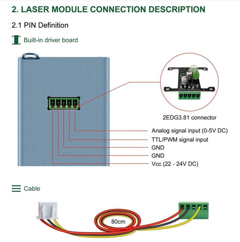
In general, you are right with the voltage assuming these are 3.3V pins and assuming you are using the V1 default firmware. The VCC on Extension-1 is labeled at 5V, so I would assume the other pins on the block are 5V pins, not 3.3V pins, but I do not know.

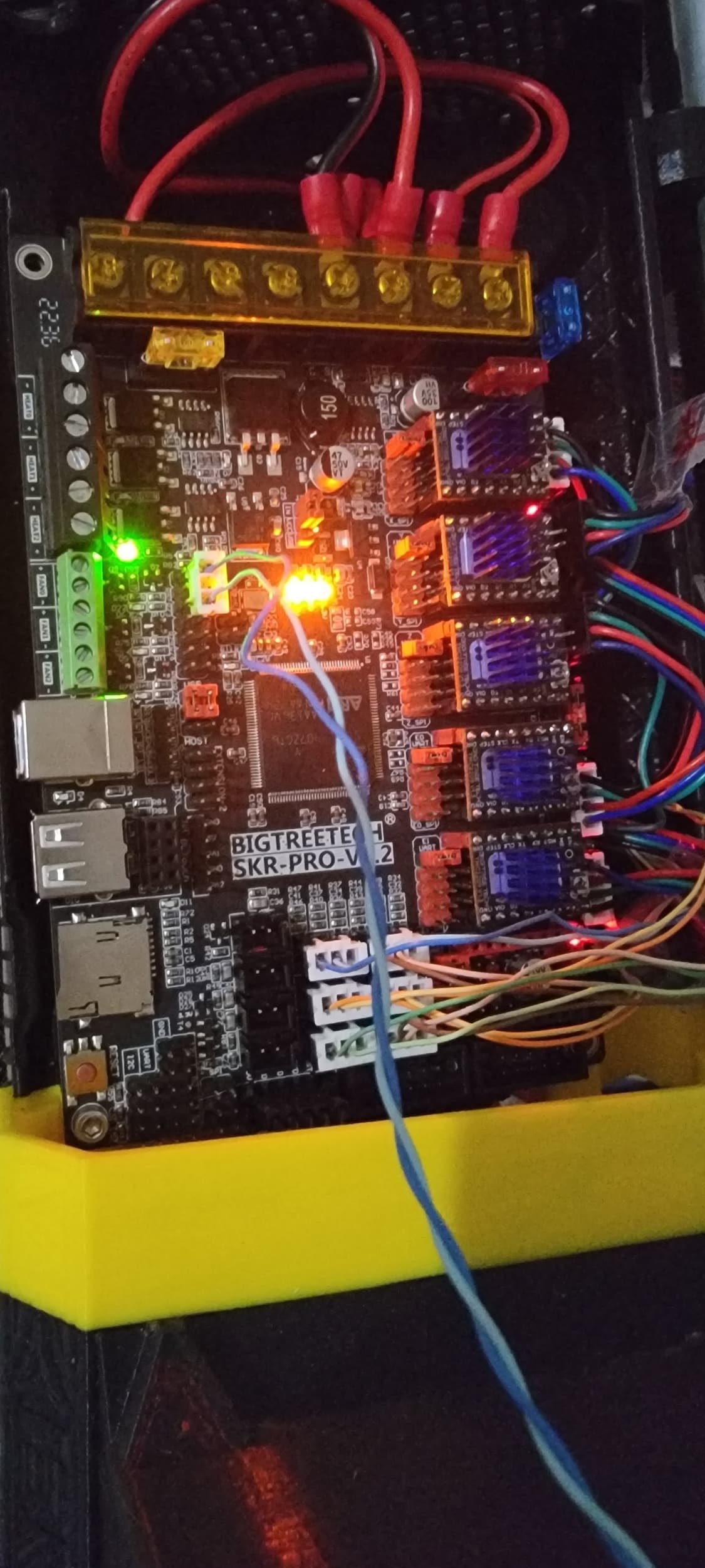
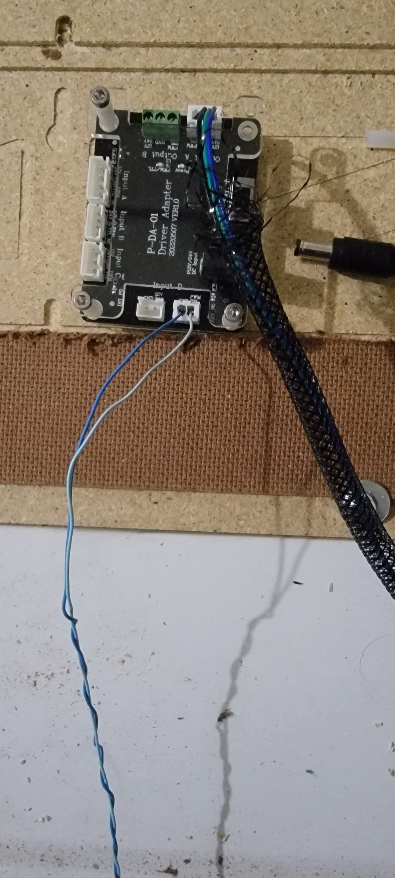
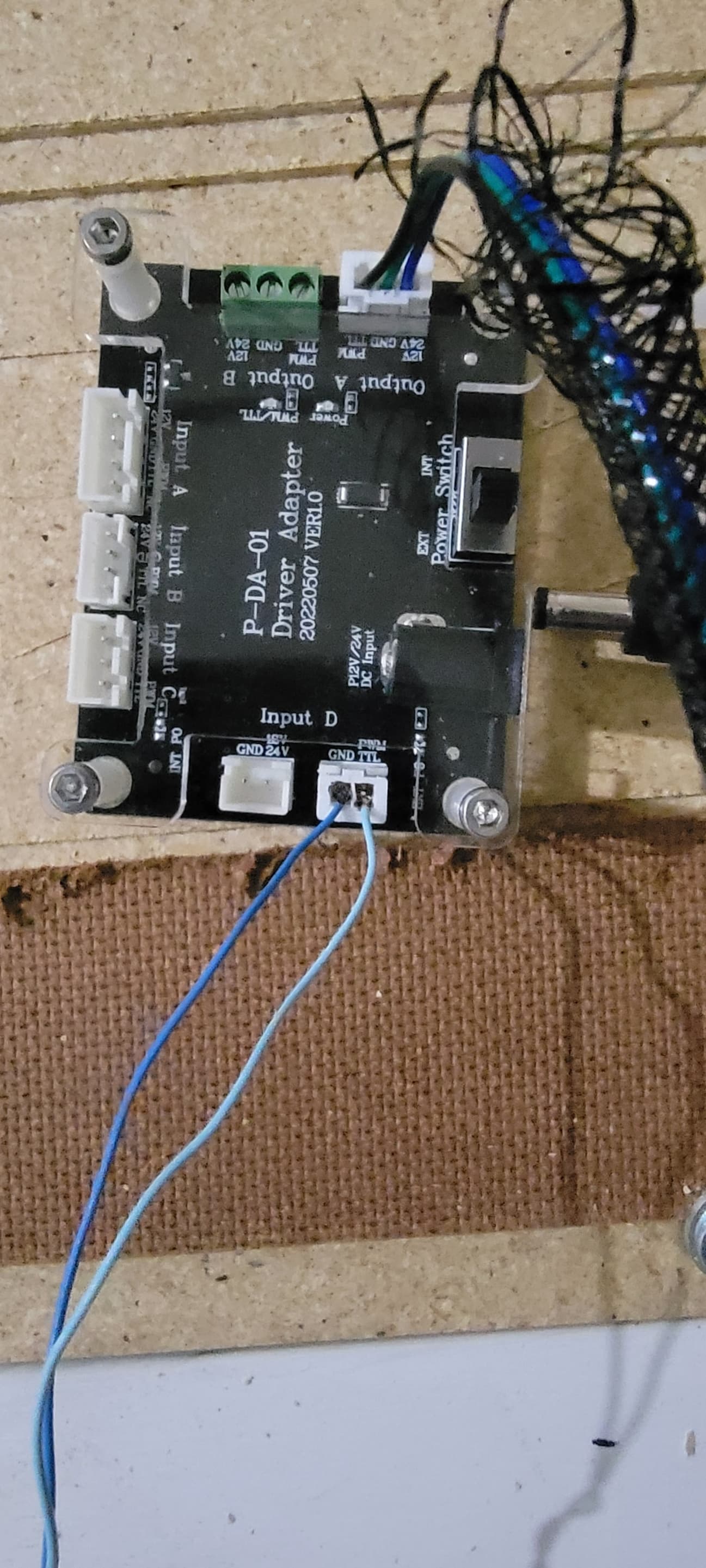
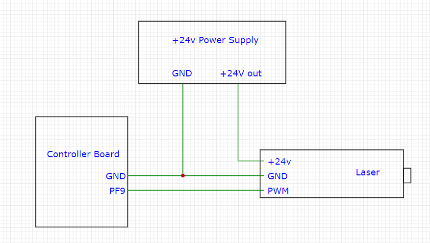
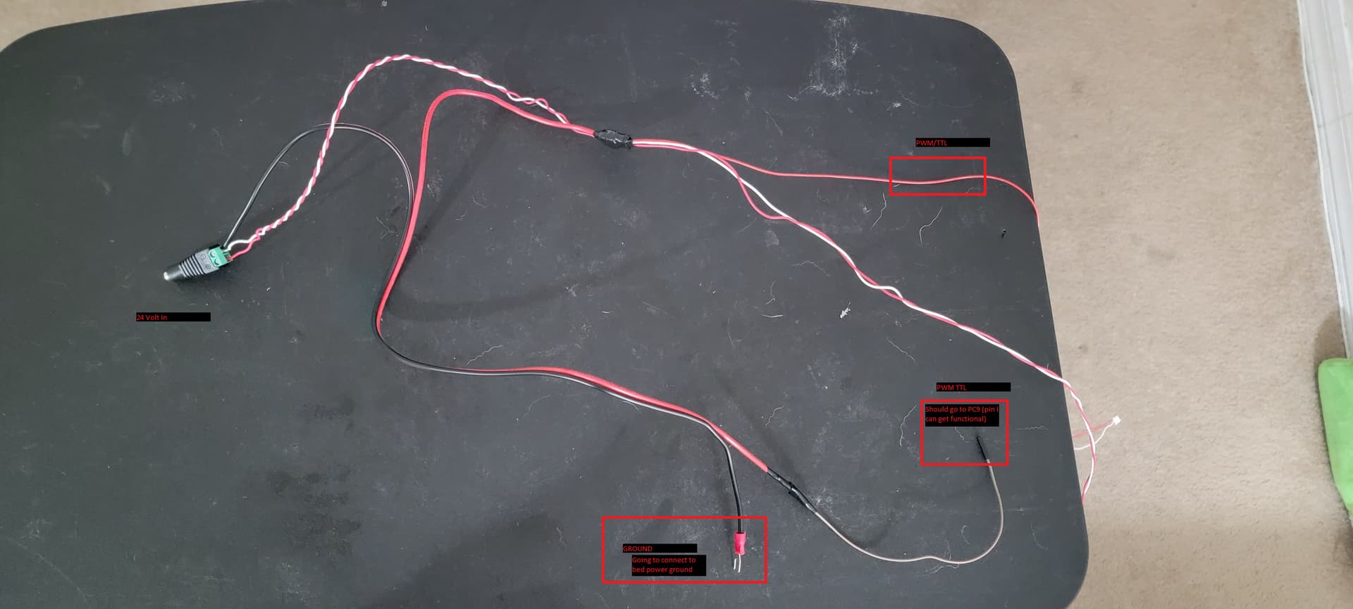
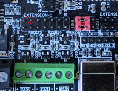
Hopefully others on this form are still following this topic, so you should get a picture of a laser hookup. According to the pinout diagram, the pin I’ve circled in red is PC9, and all the grounds are tied together, so you can use any of them, including the one adjacent to PC9:

image

Reiterating something I indicated above, M42 worked fine on the laser pin on version 113 of the firmware, but I’ve not tested on the rewritten 115 version, and I’m not home to run a test on my machine.

Did you get your laser working? I briefly returned home (just two hours at the house), so I ran a quick test of my Primo with Rambo 1.4 board running Marlin version 115.

  • I was only able to get the Marlin laser menu to fire the laser for 50ms no matter how I set the other menu items. Just a brief flash and the laser turned off.

  • M3 turned the laser on but it would go off after 1 second. With the safety timeout this is expected. I could send repeated M3 commands, and it would turn on for 1 second with each sent command.

  • M42 worked and the laser stayed on, so the pin is not considered protected, and turning it on this way avoids the safety timeout.

So, assuming you figure out your pin naming, M42 appears to be a good way to test PWM pin output. For M42, I just sent:

M42 P45 S3

…where the laser is connected to pin 45 on the Rambo board. The S3 is plenty high enough to see the laser dot but not enough to burn.

1 Like

I took a step back from the laser for the day just so I could get a win. (My upcut spiral bits also arrived so that helped) I ended up cutting my strut plates which went great.

In doing so, I did find that my laser was a bit closer than I would like it to be when doing the router cuts, so it is currently off the tool mount while I design an adapter plate to raise it a little bit.

In the meantime, I appreciate you checking the commands for me and will sit down to troubleshoot with the confirmed commands on this firmware with a fresh mind towards the troubleshooting, and hopefully get it resolved.

Alright. I just sat down with it and even though I got some really weird results, I think I FINALLY have it about 90% figured out. I have still not plugged it back into the laser as of yet for 1 reason. I’ll take you through where I’m at and what I think should solve the issue.

Long story short, for whatever reason, I can’t get PC9 to respond on either board. I just sat down with my PF9 firmware (everything else is exactly the same as default V1 firmware, only changed PC9 to PF9).

At this point, I can now get MOSTLY appropriate voltage changes through PF9 and the Ground next to PC9 (In your screenshot 1 pin to the left and right of the circled red PC9 pin). This is where I think I’m close to the solution. Using my voltmeter on these 2 pins, I was dropping to 0 and flashing up to 3.3ish volts using M3 commands. As a result, it seemed my issue was solved, and I brought the laser downstairs to test with the new pin, plugged it in to the laser adapter board, and BEFORE I plugged in the 24v power (for the laser) and decided to measure one more time before plugging the laser in to test fire.

This time when I measured, the lowest voltage I could get was .6 volts (but it consistently drops to this voltage) and then when I use M3 commands it will appropriately change voltage higher, but does not drop below the .6 volts. As such, I’m wondering if I need to add a resistor in line for the PWM signal (to get it down to 0) before I plug in the laser power?


I feel like I’m SOOOOO close, but I stopped myself to ask this question before I continue because I want to make sure I solve it right.

Thanks again for all the help.

1 Like

I’ve never had to use a pullup or pulldown resistor in an output circuit. In particular, I’ve never used them in conjunction with a PWM output. I have used them (both external resistors and internal to the microprocessor resistors) on input pins. Your results are strange enough that I have to wonder if there is an issue with your voltmeter.

A real EE would just put the pin on an oscilloscope and have an immediate answer. Note that it is not the voltage that drives the laser. It is the PWM signal telling the laser when to be on and off. The 0.6V is only concerning in that it may indicate that an S0 parameter may not be turning off the PWM. If that is the case, a pulldown resistor will not solve that issue.

I’m still incredulous that PC9 is bad on both boards. It makes me think there is something else going on here, but I don’t have any idea on what that might be. On the forum, I’ve seen a number of people hooking up a laser to the SKR Pro 1.2, and your topic is the only one that details a potentially bad PC9…twice. And, the second board has never been hooked up to the laser board.

Ummm… 24v supply for the laser? I am wondering if you have the specs for the laser because you are trying to feed it with a 3v3 PWM signal.

Also remove the adapter board, you don’t need it. I suspect your 0.6v might be coming from there as there appear to be an LED, a resistor and what looks like a diode mounted on it close to the signal line. Take your meter and check PF9 to ground when using S0 and S(whatever your max signal number is). Check for zero volts and 3v3 respectively, if that is ok plug PF9 to the laser pwm pin and gnd to gnd directly without the adapter board and try it.

The bias resistor from pwm to ground you refer to was initially to prevent the laser firing up during the uP boot up as the PWM pin on some setups could be left floating, this wont help you for your problem.

If it still doesn’t work you might want to check that the laser will work with a 3v3 PWM signal…

I was going to upload the manual, but it does not accept PDF files. I think these are the relevant sections.


I’m a bit confused by your indication to ditch the adapter board. I am using a 12 volt supply for the SKR Pro, and the laser adapter board takes the separate 24 volt adapter for the laser, and then works with the PWM signal from the SKR Pro (or is supposed to and DID during initial test firing).

Based on your suggestions, are you indicating that I should instead possibly use the driver adapter (to still provide the laser power) and then bypass the adapter board and give it the TTL/PWM signal from the SKR board? My confusion for this thought comes in for then where does the ground for the PWM signal ground out to?

The forum accepts ZIP files, so as long as the file is not bigger than the forum size limits, you can put any file inside a ZIP file and post the ZIP to the forum.

LT-4LDS-V2.zip (3.3 MB)
Laser Manual PDF in Zip

Why do you want to use the adapter board? The laser requires positive power to drive the diode (+24v in your case) , a pwm signal (PF9 in your case) and a ground reference wire which is connected to both your 24v supply and your controller board, sizing the wire for the expected current flow. from your description it appears as though the pwm signal leaving PF9 is correct but suffers from a 0.6v bias once it is connected through the adapter board… ergo…

I appreciate the graphic. Would this not damage the SKR Pro 1.2 running at only 12 volts? To my understanding, that is the entire point of the adapter board, to ensure, that you’re not combining a 12volt system and a 24 volt system, but to still be able to control it.

Additionally, I know for 100% that the laser driver board did work, as well as the SKR 1.2 because I was test firing prior to extending the cable using stepper motor extensions (because I had an extra lying around). I’ve gone back and watched the video just to make sure it actually was firing and I wasn’t making stuff up because troubleshooting this for over a week I feel like I’m going nuts.

I don’t know about your specific board, but in other cases on this forum (and personally), we’ve found there is no needed active circuitry on some of these boards. The boards are just there to make hookup easier. As for mixing 12V and 24V systems, as long as you have separate power supplies and don’t mix VCC you should be fine. You need to share PWM and ground between the laser and the SKR Pro board.

I have a NEJE A40640 that I move between machines. It came with a control board. On one machine, I use the control board, on the other, I wire directly to the laser. It works fine on both.

I’m still concerned about why PC9 does not work on either of your two boards.

1 Like

Ok. I sat down to wire up the adapter as designed and wanted to run it by you guys before I go connect/test anything.

Based on the above image and confirmed steps, I believe this should be what I’m looking for.

I’ll be measuring voltages, finding a suitable pin and confirming everything again before I connect anything to the laser, but making this adapter seemed to be my next step.

I’m assuming from this wiring that your laser will have its own power supply and that you are wiring directly to the laser. I assume the gray to big red to smaller red is one continuous connection and is not connected to anything else (like in the black blob where the size of the red wire changes). If both are true, then your wiring is okay. Note the large black and red wires are way bigger than is required. Very little current is used for a PWM signal, so the wires can be very small, and the black wire can connect to any continuous ground pin on the board (i.e. it does not need to connect directly to the terminal like is indicated by your connector).

Also, be cautious with the power connector. The screw terminals like are on this connector do not play well with stranded wire. Based on recommendations from this forum, I’ve started using Ferrules on the stranded wire for these kinds of connections.

All true and correct. I know the wire for the PWM is big on the board end for that signal, but since I’m grounding the 24 volt through the board I wanted to make sure it had an appropriate size for that voltage, and I had a few extra of the cables that came with the SKR boards.

I think I should be good on the connector as I spun it around the full copper ground wire before I screwed anything down, so it should be fairly secure, but if I have any issues checking voltage that will be the first place I check.

I’ll let you know how it goes.

Electricity and electric circuits are not necessarily intuitive. Though your black wire is attached to the ground of your SKR Pro board (running at 24V I think), it is only acting as the ground for the 5V PWM signal, and PWM signals typically draw very little current.

But even if you were running 24V, that doesn’t necessarily mean you want/need bigger wire. Here is a voltage drop calculator. This calculator is for larger wires like are used in house MAINS wiring, but it shows the concept. Set the calculator to DC and pick 14 AWG, then vary the voltage and look at the Voltage drop percentage. There are a number of things that come into play when sizing wires, but I just wanted to point out that increasing the voltage does not necessarily mean you need to increase the wire size. In fact, in many cases, you can do the opposite.

itsworking

WOOO!

I’ve got M3 control over the laser with the cable on PF8 (on custom firmware with PC9 changed to PF8) using the cable I showed above. I’m going to clean up the cabling next, confirm it works after putting the cables through sleeves, and then start testing some burns.

Thanks again for all the help! I’ll follow up after I sleeve the cable and close the control box, but I think we’re finally good to go.

2 Likes