I’m in the process of finalizing my LR3 build and am at the point of adding my laser (Laser Tree LT-4LDS-V2), which I was able to test and had functional test fires yesterday. After extending the cables (using an extra extruder extension cable) I went to test the laser again and it is now constantly firing when plugged in to the laser driver adapter.
Additionally, I’m starting to think the issue may be with the PC9 pin and ground on the SKR Pro 1.2 board I am using as I am getting a constant 2.65 volts when measured with multimeter (which would kick the laser on when the PWM/TTL is plugged in. Yesterday, using the same PWM cable and pins the laser was test firing consistently. If I plug the laser driver adapter power in, the fan comes on in the laser and does not fire (as there is no TTL/PWM signal) to trigger the fire.
Is it likely I have a bad pin on the board? What/how else can I check and resolve this?
Lastly, I do see that fan outputs are used which I believe my laser adapter should handle fine if I use it, but I want to ensure which pins I should change (if needed) in the firmware.
First off, I would disconnect the laser and connect a voltmeter to PC9 and ground. Then you can use M3/M5 g-codes to set the PWM of PC9. You can also use M42 to directly set the pin state/PWM. As you vary the PWM value you should get a commensurate change in the voltage.
If it turns out that PC9 is not functioning for some reason, you can use M42 to test the other 11 pins on the Extension-1 block. I don’t know which, if any, are PWM pins. Note that PC9 has worked for all the people requesting advice on the forum for hooking up a laser to the SKR Pro, so if yours is not working, it is likely you damaged the pin during your wiring. I mention this since if there is a problem with PC9, it is also possible you could burn out another pin unless you identify why PC9 was damaged.
As for fan pins, things have changed since the early days of lasers and Lowriders. In the past, people would use the fan pins along with M106/M107 g-code commands to set the PWM of the fan pins to turn the laser on and off. Recent versions of the Marlin firmware have explicit laser support that produces substantially higher quality laser cutting and engraving. This new support uses an explicit laser PWM pin. In addition, on most control boards, fan pins are controlled by ground-side switching rather than the PWM being implemented on the VCC side. Only a minority of lasers can handle ground-side switching directly, with the majority needing a bit of extra electronics to make the fan pins work as PWM input to the laser.
If you need to switch to a different pin, V1 defines the laser PWM pin in the top of the configuration.h file. You will need to make the change, recompile, and reflash your board. If you switch to a pin used by some other board system (like a fan pin), you may also need to redefine the other mapping to that pin to avoid a conflict. For the SKR Pro 1.2 board, the pins mappings are primarily defined in src/pins/stm32f4/pins_BTT_SKR_PRO_common.h.
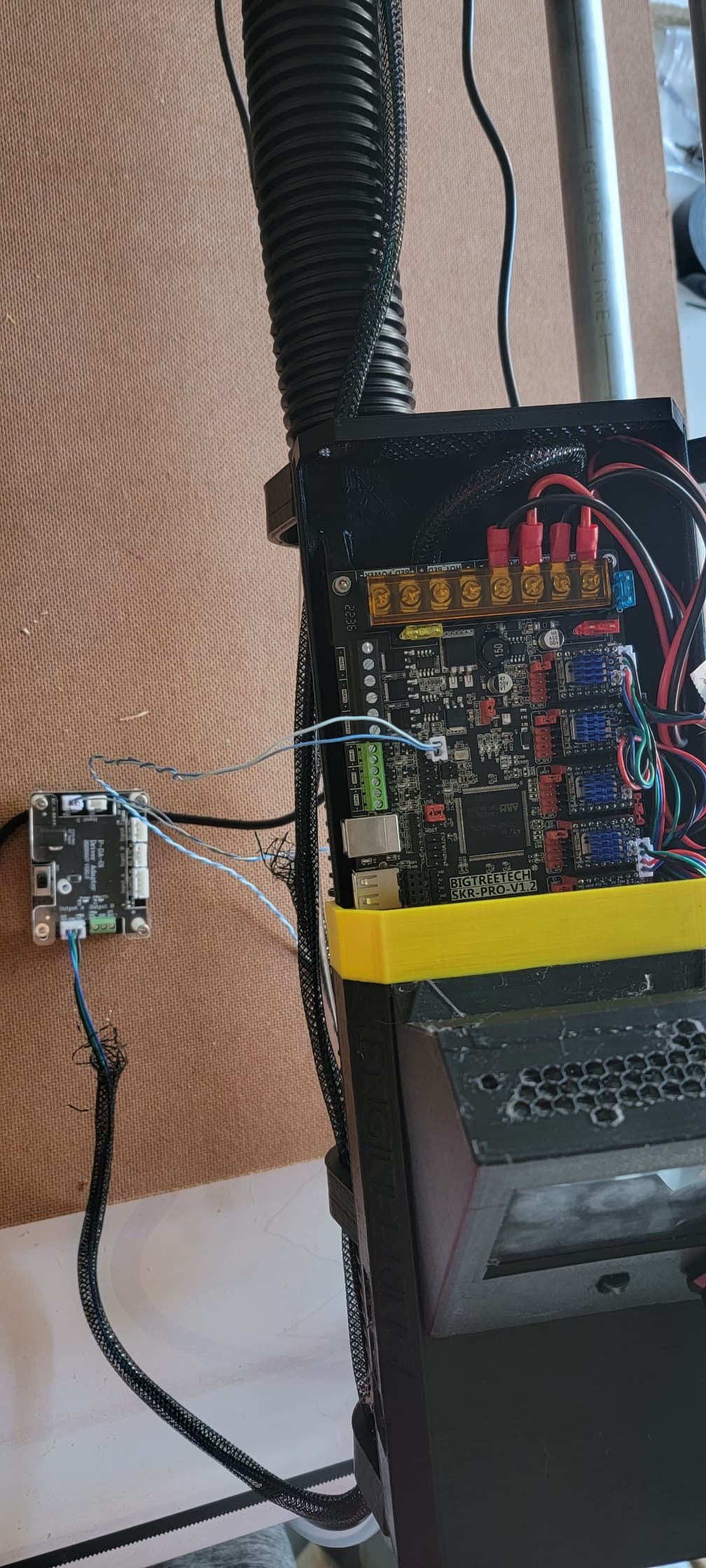
To confirm, the laser adapter board was just plugged in again for the picture to show how it was before I started measuring. I had already cut the cable and measured using the multimeter.
The PC9 and ground continuously measure 2.65 Volts, after having changed the laser power both in Marlin mode and Touch mode with the terminal.
Before I start looking at flashing firmware/changing pins and finally another board I have here at the house I’d like to confirm the M42 command and run that. From what I can tell it should look like
M42 PC9 S1
and from there progressively increase the S from 1 to 255 which should see increasing voltage?
If this isn’t the case, from what I have been able to find online, PF8 and PF9 should also be PWM capable pins, which as you indicated should just be changing the PC9 to PF9 (for example) re-compiling, flashing, and then testing this again on the new pin?
Additionally, can I use the M42 command as shown to set the PF9 pin instead and measure from there prior to flashing the new firmware to confirm the pin should work before changing firmware?
Yes, that is the format for an M42. Not sure, but you may have to set the pin for output using the T parameter before sending a separate M42 to set the PWM.
F8 and PF9 should also be PWM capable pins, which as you indicated should just be changing the PC9 to PF9 (for example) re-compiling, flashing, and then testing this again on the new pin?
That is correct. I’m away from my main machine, so I cannot give you the exact line, but the define for the laser PWM pins is in the first half dozen lines of the configuration.h file…maybe even the first line.
Note that the 2.65 Volts is a strange number for the voltage of the PC9 pin and might indicate that the pin is floating.
1 Step forward, 2 steps back. After flashing with freshly compiled firmware, I’m now getting 0 voltage on PF9 (and to confirm the extension ports were still on, I measured the PC9 and once again got 2.65 volts).
I’ll take a look through the firmware and see if there’s any conflict, but I didn’t at first glance before compiling it this time.
Any ideas why that would give no voltage after flash? (I did adjust again using M42 commands with no change)
I’m planning to go back to the original firmware and test the M42 commands again on PF9 in the meantime.
I have a guess, and if I’m right, you need to go back and check PC9 with M3/M5. If you look at the g-code documentation for M42 there is this flag:
So, it is possible when you assigned the PF9 to the laser PWM, it becomes a protected pin. I used M42 with my laser pin on a previous version of the Marlin firmware, and it worked fine, but I know there was a major rewrite of the laser logic in Marlin recently, so it is possible that it is now treated as a protected pin.
So, check PF9 with M3/M5. Alternately, use the I flag with M42 to override protection to test the pin.
At this point I’m thinking since I know it was originally working I may just bite the bullet and open my second board, swap the wires over and check everything. Worst case, I can use this board for the ZenXY project I plan to start next.
I have some concerns about what is going on. When you changed PC9 to PF9, did you plug that pin into the laser control board? If you reverse back to using PC9, does PF9 again work with M42? My concern is that plugging the SKR Pro pins into the laser control board is damaging those pins. If that is the case, you may end up damaging your new board in the same way.
Start by going back to using PC9 and checking the PF9 pin with M42. You want to make sure you’ve not damaged the PF9 pin.
I don’t believe anything should be damaged as I did not PF9 into the laser control board, just attempted to measure on the multimeter. Additionally if it was appropriately being controlled in the firmware it should have allowed me to use the laser control in Marlin mode to check the voltage.
Flashing this board back to base firmware and testing the PF9 pin again was on my list of continuation of troubleshooting. Additionally, the plan was to verify the PWM/TTL signal out of the new board before plugging it into the laser again.
Either way, taking a break for the night, and will be back at it again tomorrow. I’ll post my findings and let you know.
I ended up flashing and testing the original firmware and am getting proper change of voltage on the PF9 pin again, so no damage there.
I then ended up flashing the firmware to the second board and switched all the cables over. I was able to perform homing, and all test functionality. I then powered down the board, plugged in to PC9 and Ground to measure the voltage, powered it back up and to add to my confusion got 0 voltage, regardless of changing via command or via Marlin mode/knob changes. To be clear this board has never been plugged in to the Laser Driver adapter as of yet, and this SKR Pro 1.2 is fresh out of the box.
If you haven’t already, download a fresh copy of the firmware from the V1 site and flash your board with the provided binary. Make sure the file is renamed on the card. That will ensure that the firmware on the board is exactly the version created by V1. Also use your voltmeter and wiring to check the voltage of some VCC pins just to verify that the connection to pins using your wiring is working correctly.
Both boards are currently flashed to “stock” v1 specifically - Marlin_V1CNC_SkrPro_DualLR_2209_2.1.1_515.
When I go to Marlin mode and set the laser power I should see the voltage change on the PC9 pin, correct? After flashing the stock firmware this is when I was getting 0 volts on the second board (again before having plugged anything in to the laser board. I only attempted to measure and am getting 0 volts, even directly at the pins (not measuring through wiring). Which other pins should I test?
I’m going to re-flash once again in case something weird/odd happened, but I’m expecting to be in the same boat after another stock re-flash.
Debugging things through a forum can be frustrating. Things that should take moments to test in person can take a lot of time and effort through written text. For your situation I see the following:
Other are not having the issues you describe, so whatever is going on is not a common problem.
The chance of two boards being bad is very small, so it is likely that something in your setup, tools, or methodology is at the root of the issues.
When you mentioned measuring directly at the pins, I cringed a bit. With a lot of boards, even a brief short between an output pin and ground can burn out a pin. I don’t know how fault tolerant the SKR Pro board is. The Rambo board is very fault tolerant, so shorting never causes issues, but I’ve burned out a lot of pins on Arduino boards over the years. When measuring pin voltage, I use Dupont wires taped carefully to my voltmeter probes.
Moving forward, you want to eliminate all the variables you can.
You’ve been messing with pin assignments, so reflash the board with the binary that V1 provides. Make absolutely sure that the firmware extension is renamed after your attempt at flashing.
Do any menu operations from Marlin mode (hold the control knob down for several seconds), not TFT mode. Marlin mode directly interfaces to Marlin, where TFT mode uses the firmware on the TFT board to send g-codes to Marlin.
Make sure your board is powered by an external power supply, not just through the USB cable. I believe this also means setting a jumper.
Carefully test your voltmeter using any 5V and GND on the board. You want to make sure your setup is correctly reading 5V from the board. You can find a pinout diagram here.
Test your voltmeter using the fan pins. Fan pins and can be controlled using M106 and M107 g-codes. These are 12V pins, but testing them will assure you that your meter setup is reading PWM signals correctly.
Make absolutely sure you’ve correctly identified the location of PC9
Being clear, I measured through the white JST plug I had set, not “directly” on the pins, so no shorts should have occurred.
Going through the list
I flashed with stock firmware both last night and this morning. This is directly from the site, not the custom change for PF9 done previously.
I have consistently tried changing the laser output via Marlin to measure mostly because it’s easier than typing in the commands. Through Marlin I have gotten no change on the voltage.
Board is powered via 12 volt power supply to the board and not via USB.
5v tests correct on the Extension 1 (directly under the same ground we use for the laser pc9 pwm ground) confirming both location of the PC9 pin and that 5volt works.
Fan Pins 0 gave me appropriate varying voltages adjusting the fan speed with touch screen mode.
I’m running out of ideas, but there are a couple of things to mention. You are installing version 515 (V1 numbering). This version introduced some new laser features. I don’t think they impact you, but I’m going to mention them anyway. First, this version introduced a laser safety shutdown. If the machine does not move for 1 second (firmware settable), the laser is shut down. I don’t believe this applies to turning the laser on through the menu, but I’m not sure. I’m away from my machine, so I cannot run a test.
One thing you can do if you want to rule this out is to install the previous (514) version of the firmware. It did not have this feature. Note the Marlin mode menu for the laser was confusing in the previous version since you needed to turn the laser “off” in order to place it in manual mode.
While it is not impacting you (yet), with the newest version, you need to send a “M3 I” before you can use inline laser commands.
I was running version 513 (V1 version) of Marlin before I upgraded. I know that M42 worked to set the laser pin PWM in that version.
I guess my only suggestion is to flash an older version of the firmware to see if you have the same problems or if features of the new version might be getting in the way of your voltage testing.
The only other thing to mention is that we’ve had a few SKR Pro boards that have lost their bootloaders. This means that inserting the SD card and starting things up, would not flash the firmware. The way to see if that is happening is to see if the file extension has changed.
That being said, I may have found the issue with the changes I did to firmware last night for PF9. PC9 was still set to Servo1 in the pin configuration where PF9 was set to a temp. I have adjusted this in the pins file, as well as changed the laser spindle line to PF9, and will try with the PF9 pin adjusted firmware again since we know this was able to give me adjusting values.
If this doesn’t work I’ll take a look at the old firmware and see where we get.
Back to stock firmware. Getting 3.3 volts out of PC9 pin now (which finally seems like the right voltage) but it will not change regardless of commands.
At this point, just to satisfy my curiosity, get things running, and get started, after looking at Lightburn, it looks like the M106/107 commands to control fan PWM still work, and based on the GCODE generated, looks like it should still function. As my laser driver adapter also has an input for 12v and ground I am looking at using the Fan 0, and attempting to work with this gcode.
Please let me know if you think this sounds like a bad test? From what I can tell, it should get me functional (while not ideal), and I can move forward from there.
I don’t think this is a dangerous test, but chances are, it will not work. It definitely won’t work if you share a power supply between the two boards. For the fan pins, PWM is switched on the ground side, not the VCC side. On a positive note, that means you can use the ground pin to create PWM for any other VCC pin, no matter what the voltage (including 3.3V and 5V VCC pins). Just use the ground pin from the fan socket and pick any VCC pin for the other side.
I have no personal experience fixing this problem, but if I wanted to use M106/M107 to control my laser, and if PF9 was an unused PWM pin, I would try assigning PF9 as a fan pin. I believe this would give you PWM on the 3.3V side, not ground. I’m just a hobbyist when it comes to electronics, but if I wanted to fix the 12V fan pin with some extra electronics, I’d be looking for a way to isolate the input signal from the output signal…something that does not share a ground, like an opticoupler module. The right kind of level converter module might also work.