Looks good. A video of it doing the wheelies would be fun to watch. Glad you got that belt system to work for you. What size timing pulley did you use on the motor?
1 Like
All the pulleys on this machine are probably 16- or 20-tooth IIRC. Most of the time I don’t really care too much as I actually command and measure axis movement and adjust the steps/mm to get them to match. Edward Chew’s TimSav documentation calls out a 20-tooth pulley for the hardware I stole from TimSavX2 (now being dismantled) so that one is probably 20-tooth… and steps/mm of 80 seems to confirm. The other axis, with 78-tooth printed pulleys, has a steps/mm of 83.88 for proper movement… so not sure.
The “wheelies” thing appeared as “bounce” as the axis changes direction. I had to add the weight of my little bench vise to hold it down with higher acceleration values. I ultimately just slowed it down until the tractors quit bouncing with a direction change.
1 Like
They are probably not 16T as the belt seemed to catch on the sides of V-Slot when I used them. I did not have any 20T at the time. My 1st new endplate print pulled up on the corners, so I leveled the bed better and trying it again today. I don’t have the heated bed for that machine hooked, but that would probably fix this problem. I added some more holes to the plate to have more perimeters & using less infill thus giving a shorter print time. Will see if it is strong enough. Should be less than 2.5 hour print where yesterdays print was close to 4 hours.
Alright…
TimSavX2 is no more. SIL finished his large foam project for his church’s children’s room… and I have no real need for such a machine…
Still have a TimSav to play with…
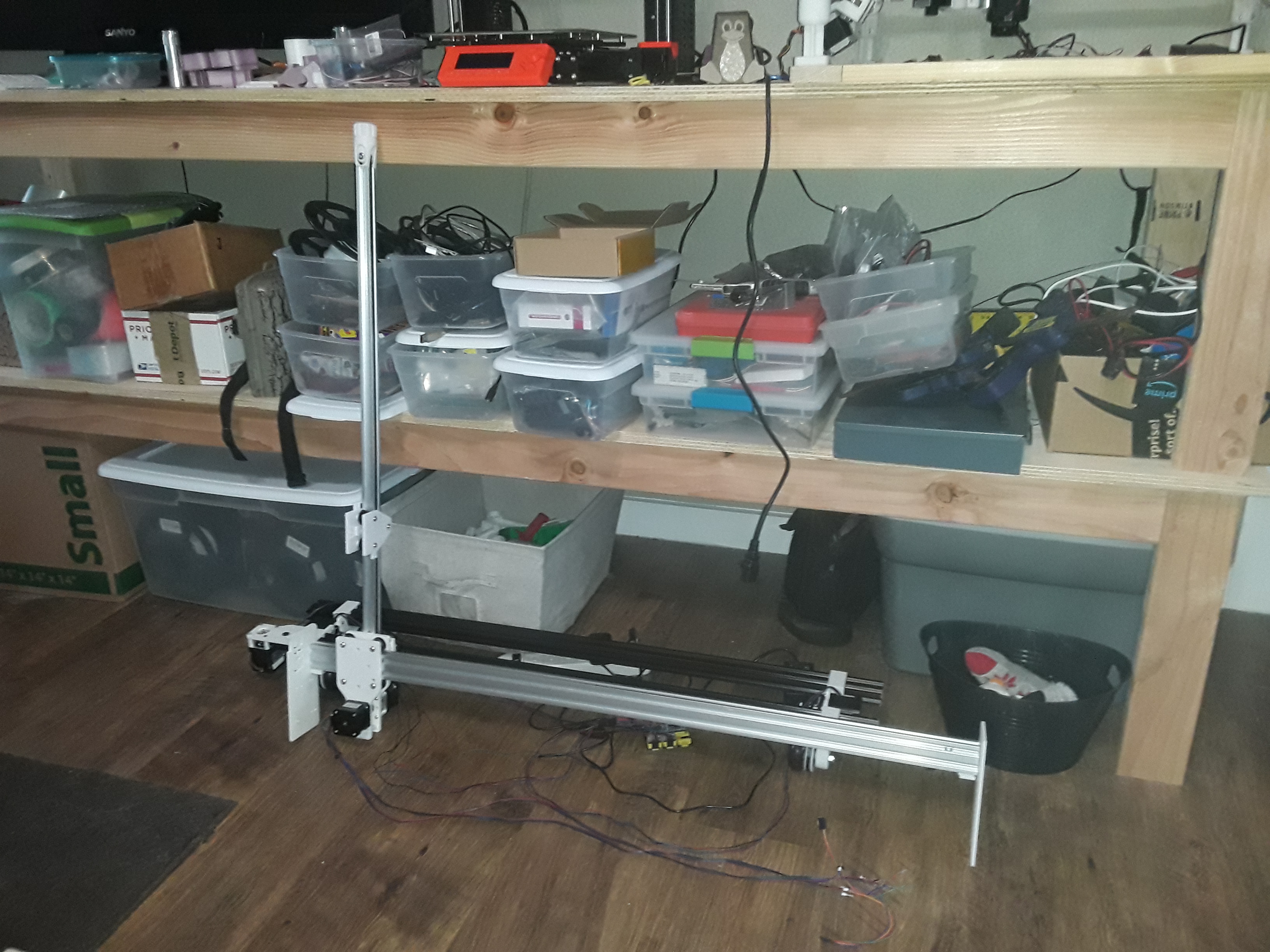
New horizontal surface to start piling stuff up on…
Go to thinking… what’s better than FoamRipper? TWO FoamRippers! Or, at least, one FoamRipper… and a Mini?
Still have the cutoff door piece from FR… could make a MiniFR. Lots of stuff I do really doesn’t require the full area of FR and this might be a really handy size. At the very least, it’ll be easier to get around it to work on during further development.
Gotta spend the hours of my day anyway… why not piddling with this stuff?
– David
3 Likes
This is perhaps a bit much to attempt, since it looks like it requires two 6 axis arms.
Scaling back the number of dimensions, I would think with a pair of 2-axis controls that are controlled independently instead of synchronized to each other you should be able to cut out a 2D shape and also control the slope of the edge. For an object sliced into layers you might get a decent approximation.
If your object is convex then dual 3-axis controls should be able to cut out the shape with a straight wire between them. I’m not sure what you would make with it…
1 Like
That is way cool, Jamie! But I really have little need for a hot-wire machine now that SIL has completed the foam project he did for his church. So I’ve actually dismantled the TimSavX2 hot-wire machine I built… leaving me with one TimSav 2-axis CNC machine (to play with on down the road) and a bunch of parts I can use to finish out this rolling plotter/gantry project.
But that is cool. I’ve never messed with robot arms… too many degrees of freedom for my tired, old, brain to deal with. 

One of the youtube accounts I follow uses a full size kuka arm with a spindle as a 6 axis cnc router. It’s neat to watch work.
3 Likes
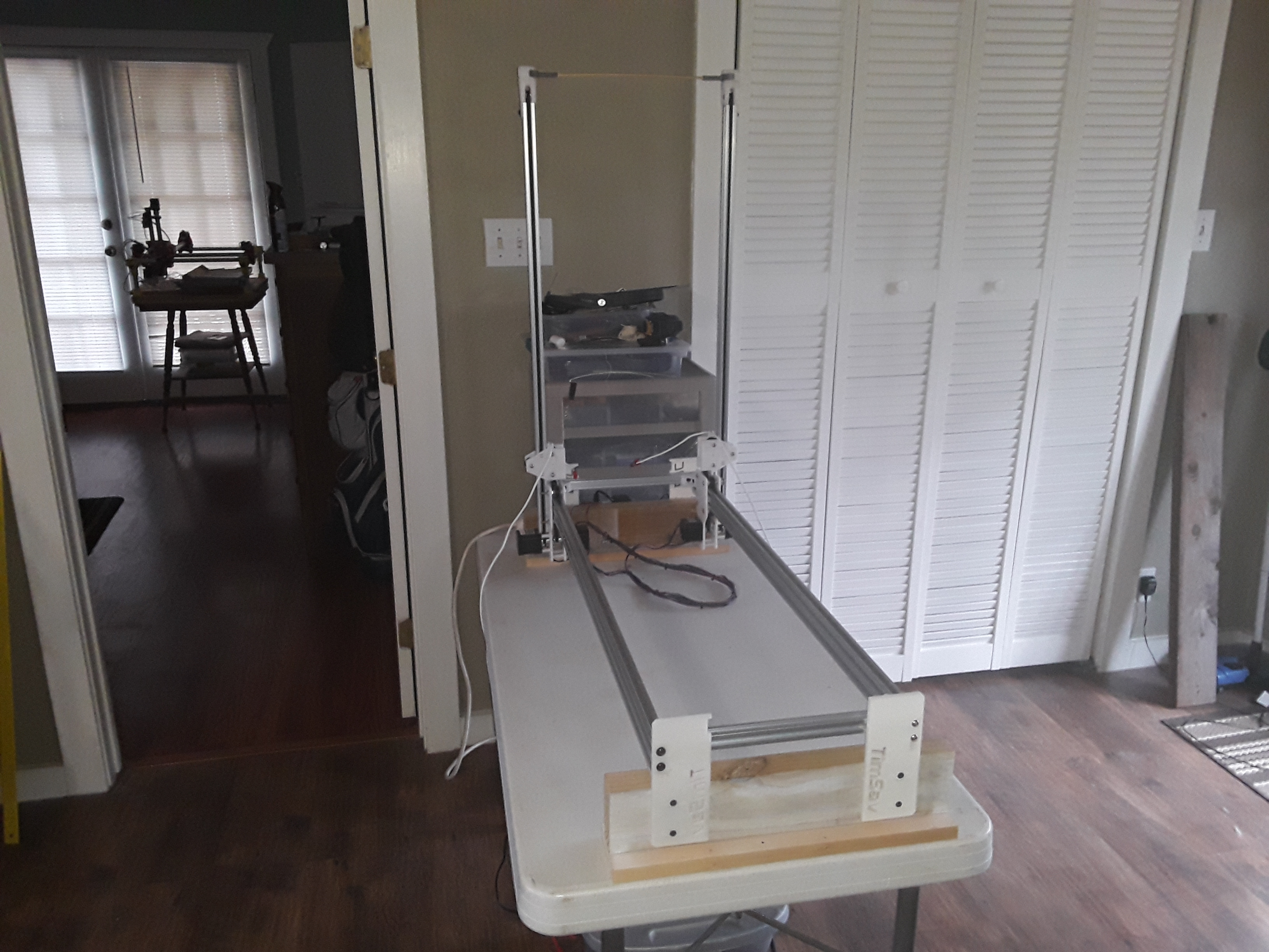
More progress on the rolling plotter/gantry…
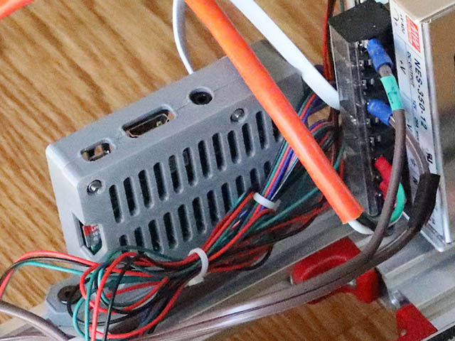
I printed a couple of plates to mount the RPi and CNC controller boards on the back rail…
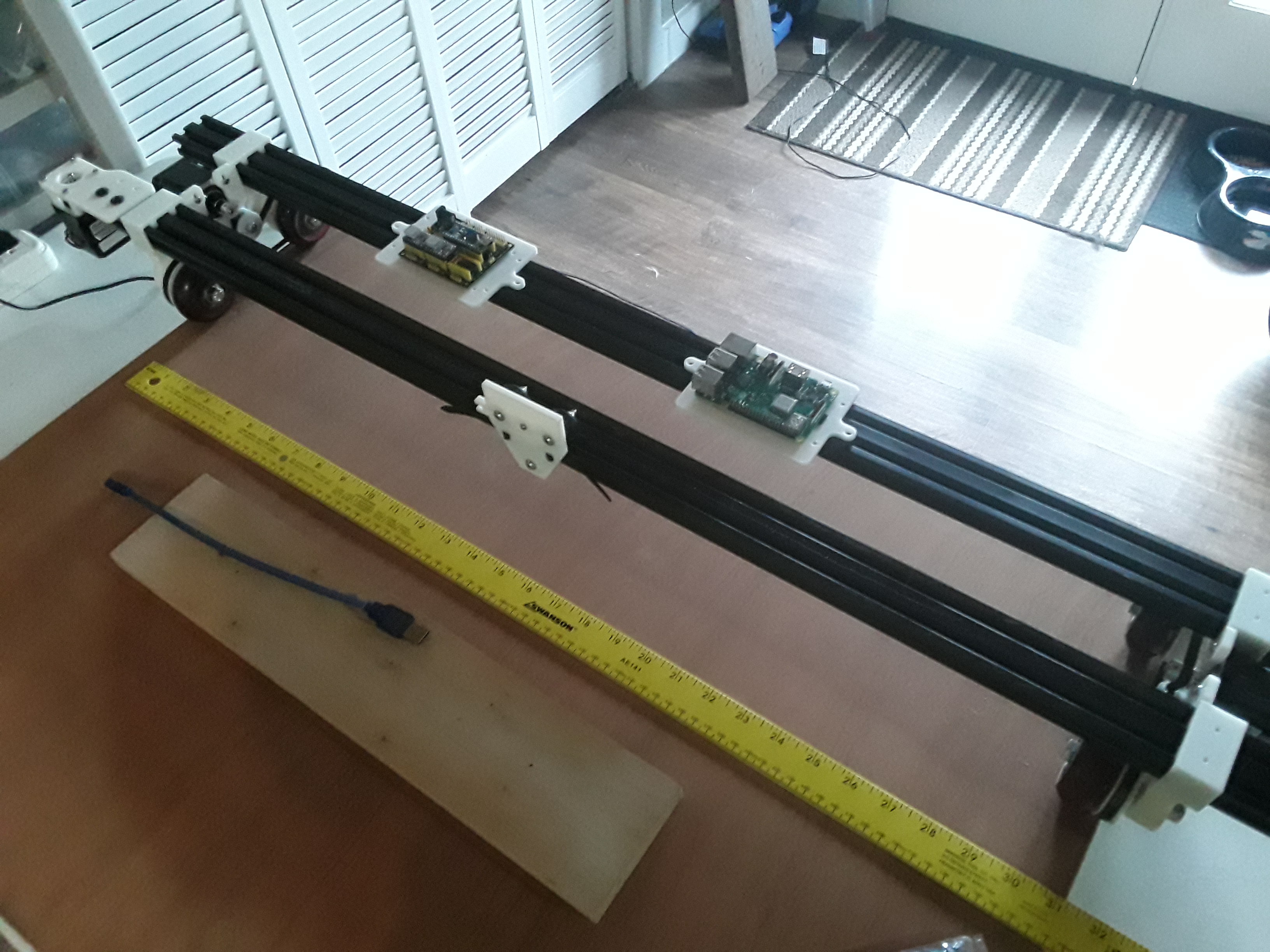
and then started working on the Z-axis.
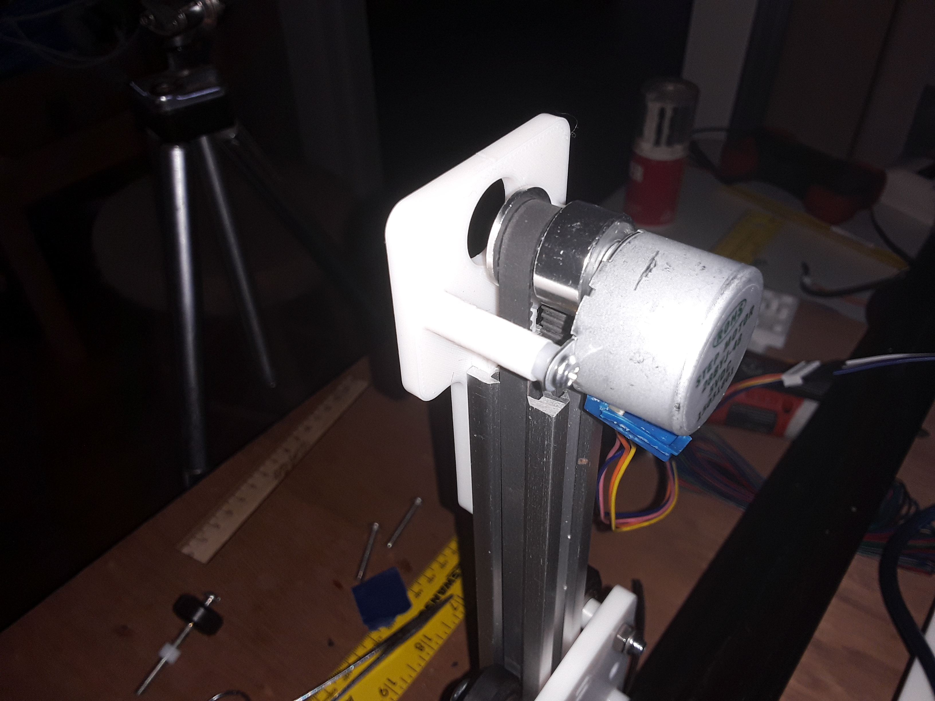
After a “discussion” over on my FT thread about the various forms of belt-drive, I decided to see if I could make the entire machine be belt-driven. I came up with a smaller version of the Y-axis linear stage, to use as a Z-axis. As I don’t ever expect to lift anything heavier than a laser, needle cutter, or a pen… I wanted to try using a very inexpensive 28BYJ-48 geared stepper motor that I had used on a couple of projects before. But first I needed to perform a well-known “unipolar to bipolar” conversion/hack on it (you cut a trace on the internal PCB and remove the 5th wire) to increase its torque and allow it to be driven with the little stepstick driver modules used on the other axes. Here it is in action…
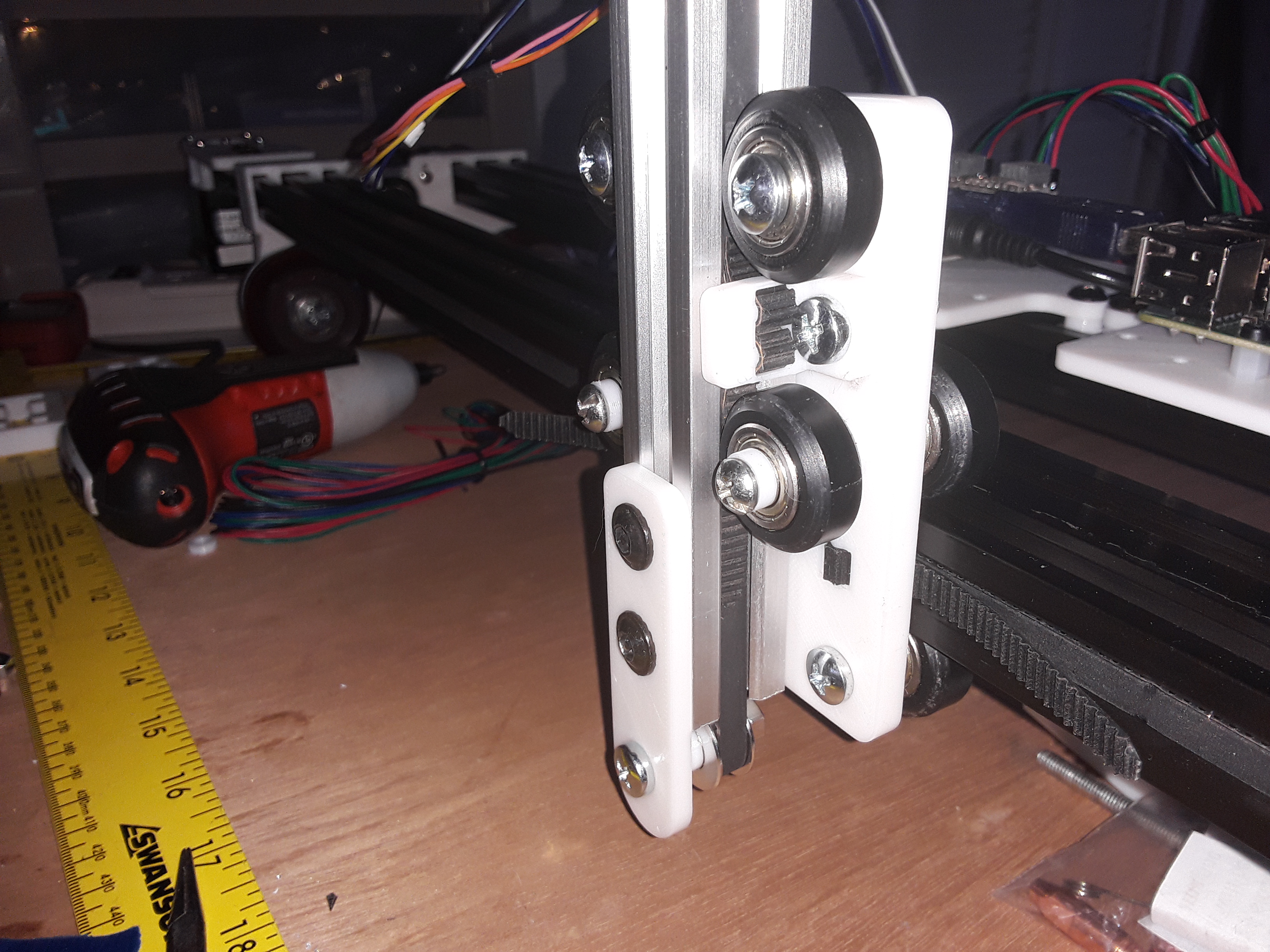
I strained my brain to try to simplify the mechanism as much as possible and finally decided on a “shared carriage” assembly… where the Y-axis carriage plate is also the Z-axis carriage plate. So while the Z-axis carriage remains fixed in the Z-axis, the entire assembly moves up and down. I haven’t added a tool mount yet but being V-slot extrusion, it’s easy to attach stuff to it. The range of motion here is only about 55 millimeters and is limited by the lower end of the Z-axis hitting the spoilboard. I guess I’ll eventually need to fashion 2x4 elevated guides for the trucks/tractors to run on if I have thicker materials I need to work on.
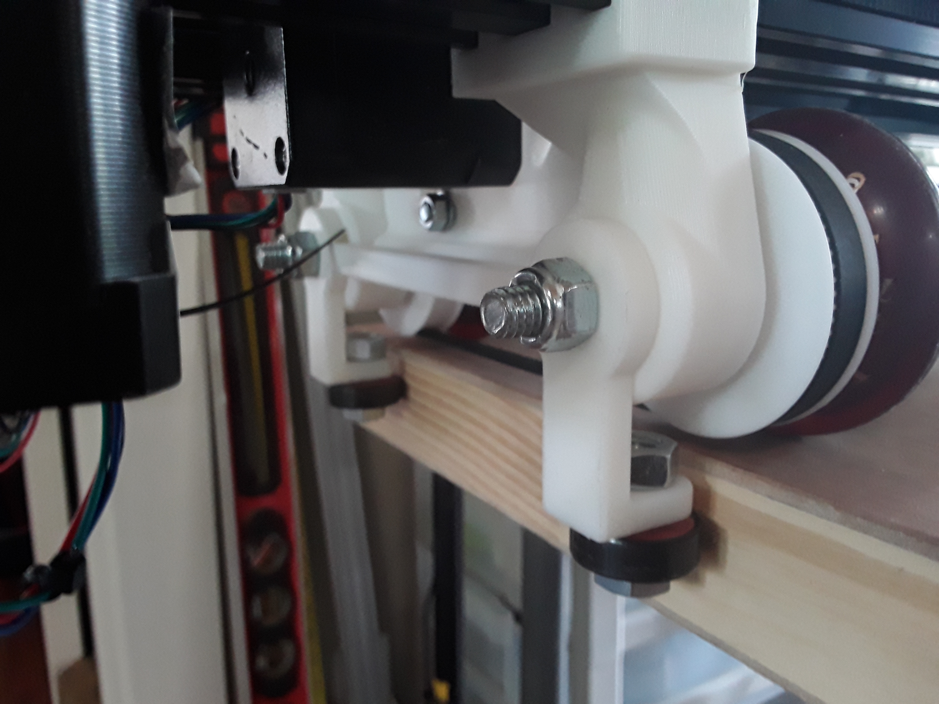
Here are detailed photos of the Z-axis assembly. The “hacked” (note the blue plastic piece just hanging…) 28BYJ-48 geared stepper motor, with IIRC a 20-tooth GT2 pulley…
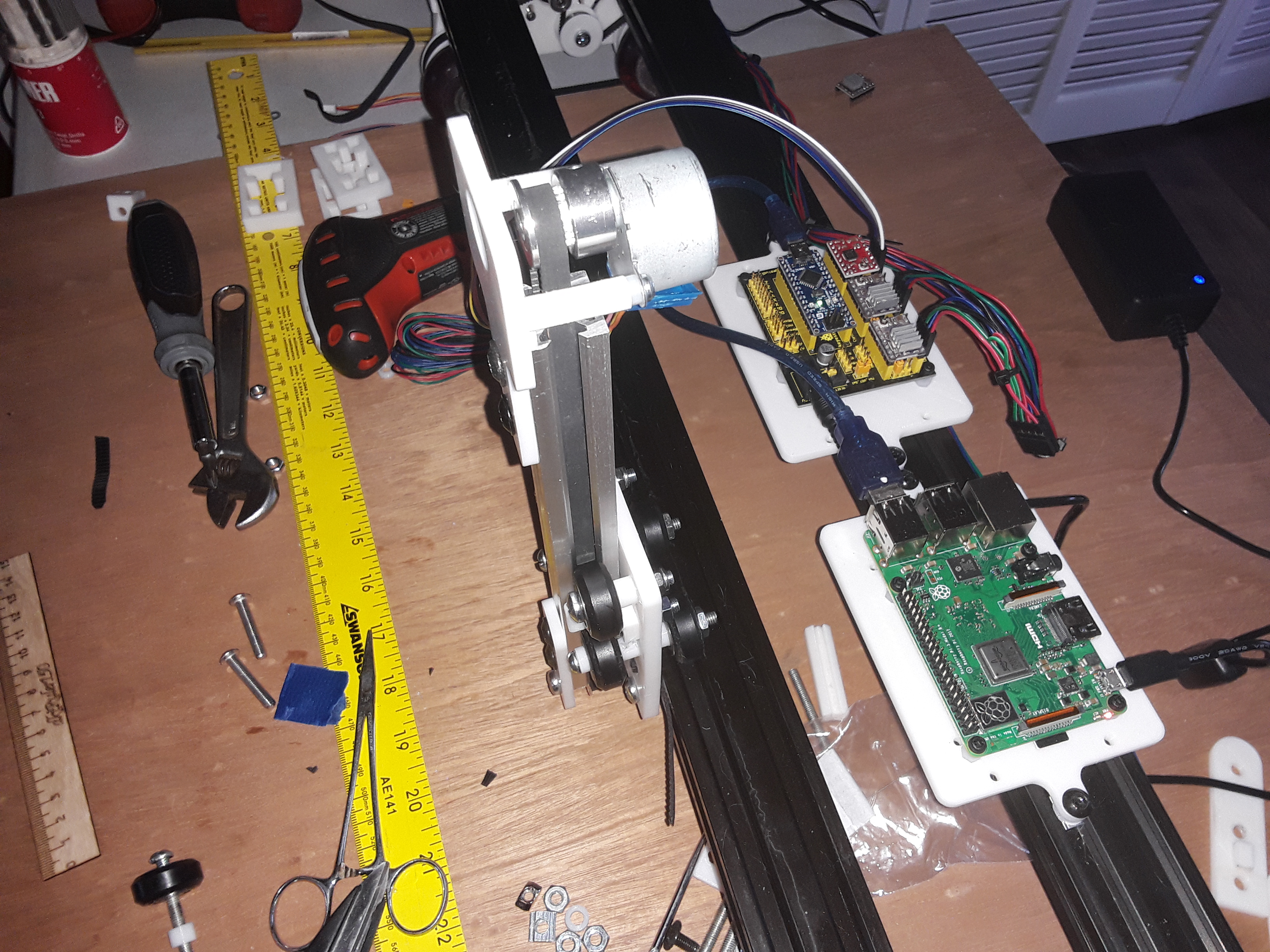
Back-side shot showing the stepper motor now driven by A4988 driver (had one sitting there). X and Y are driven with DRV8825 drivers and RPi-3B+ on the left…
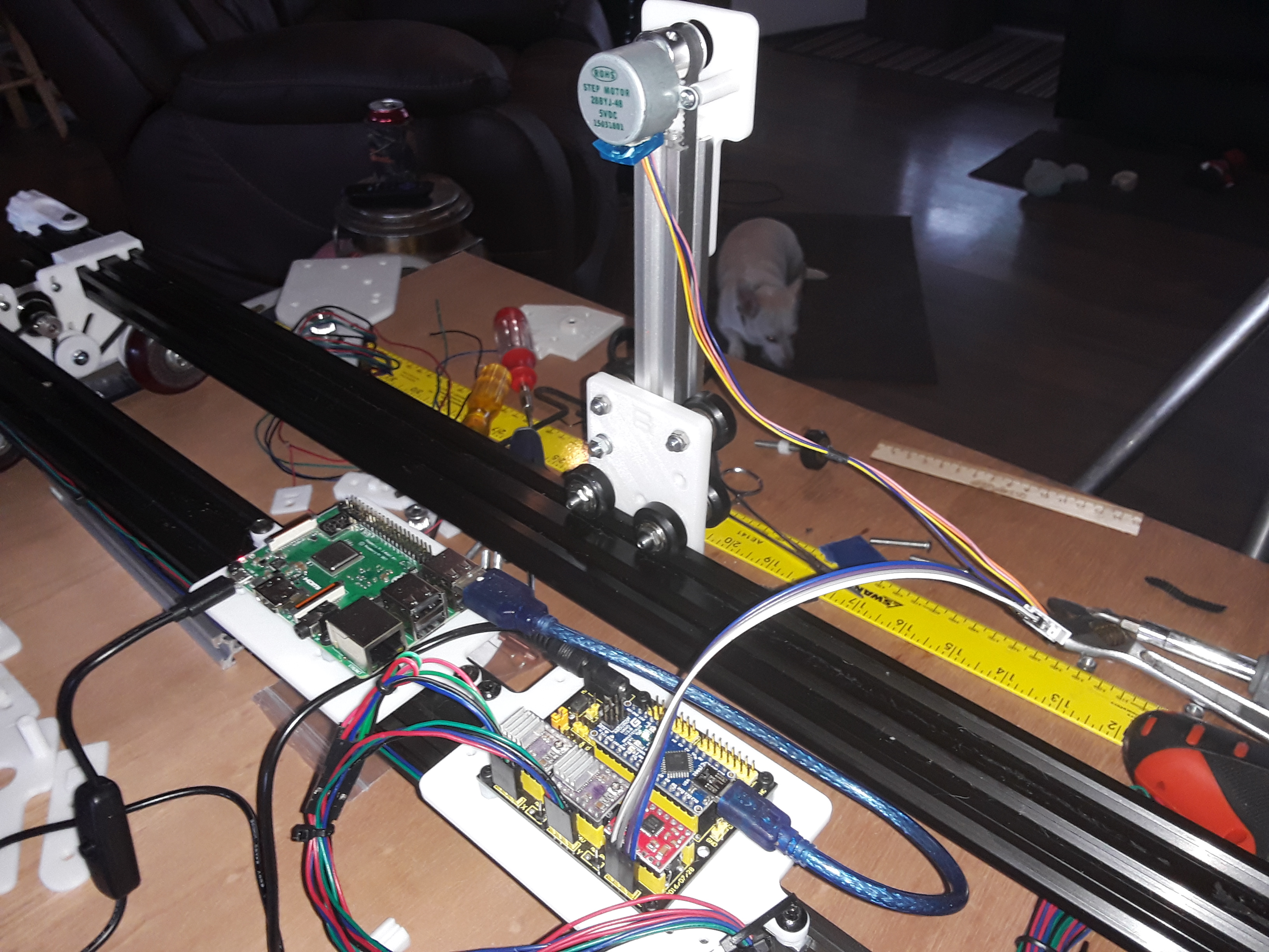
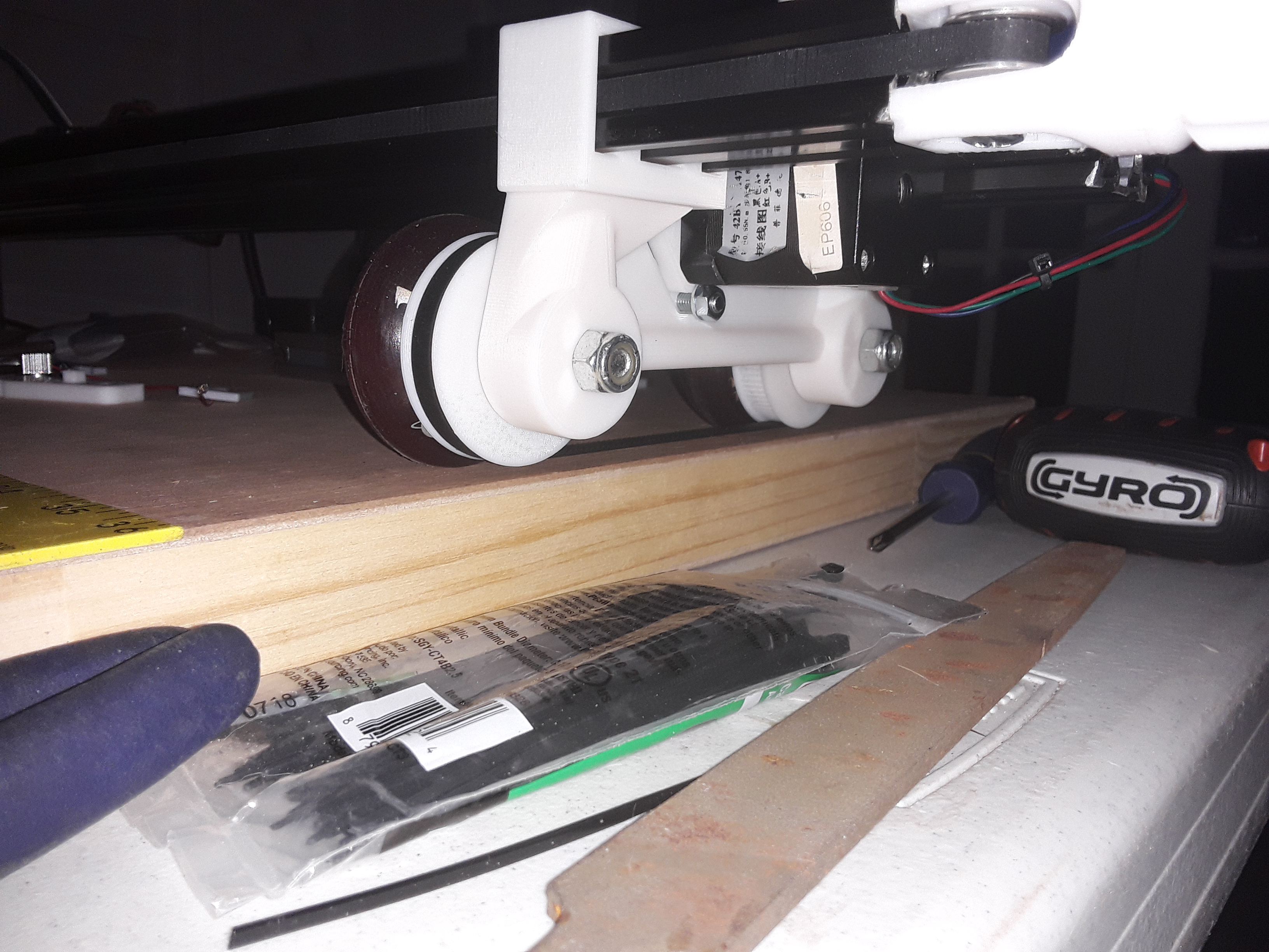
Frontal shot of the Z-axis assembly and the shared carriage plate, with wheels front and back…
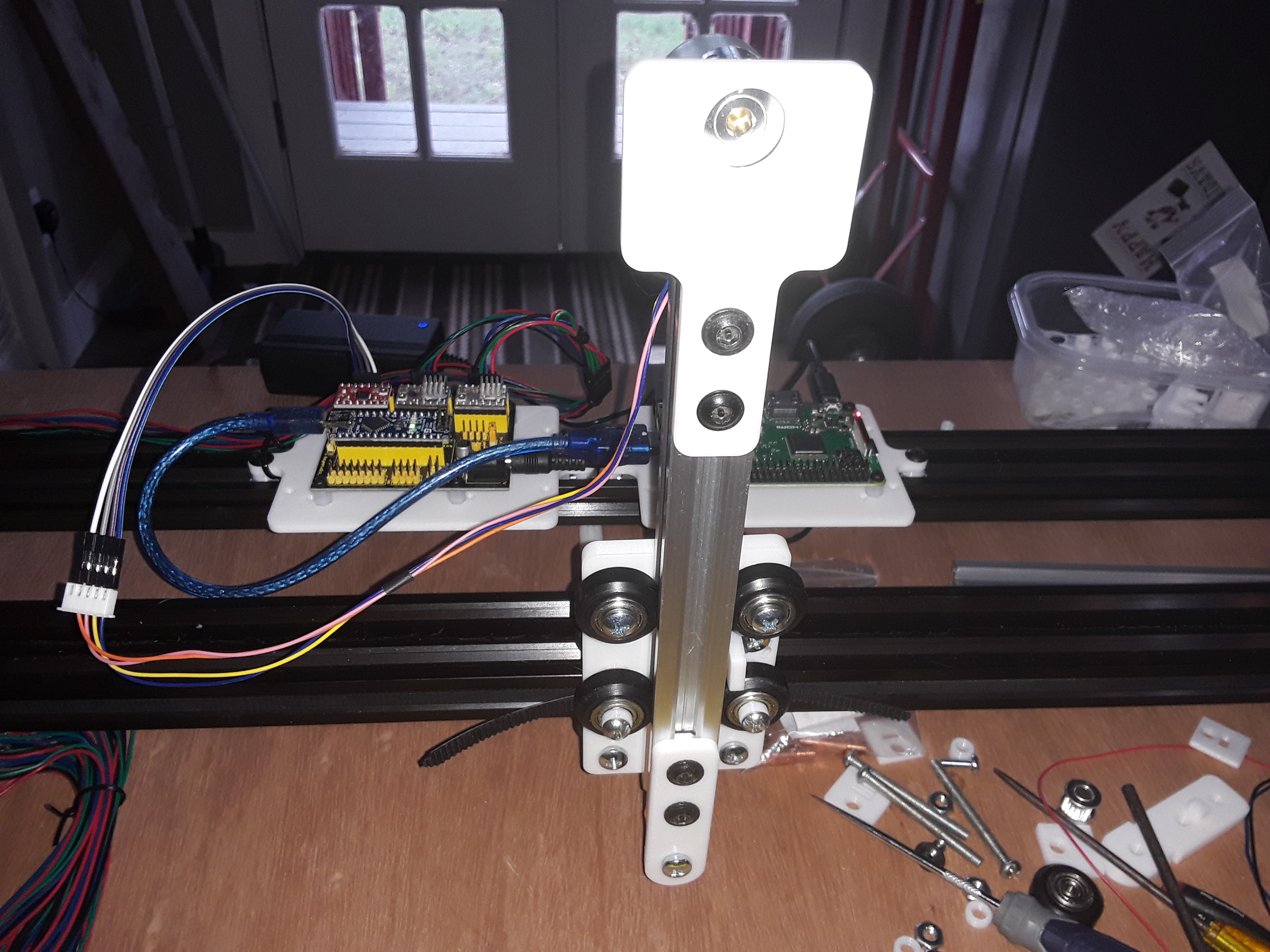
Z-axis “carriage” is just a little block capturing the belt ends and bolted to the Y-axis carriage…
Another shot of the hacked 28BYJ-48 stepper motor and just enough belt clearance inside the extrusion…
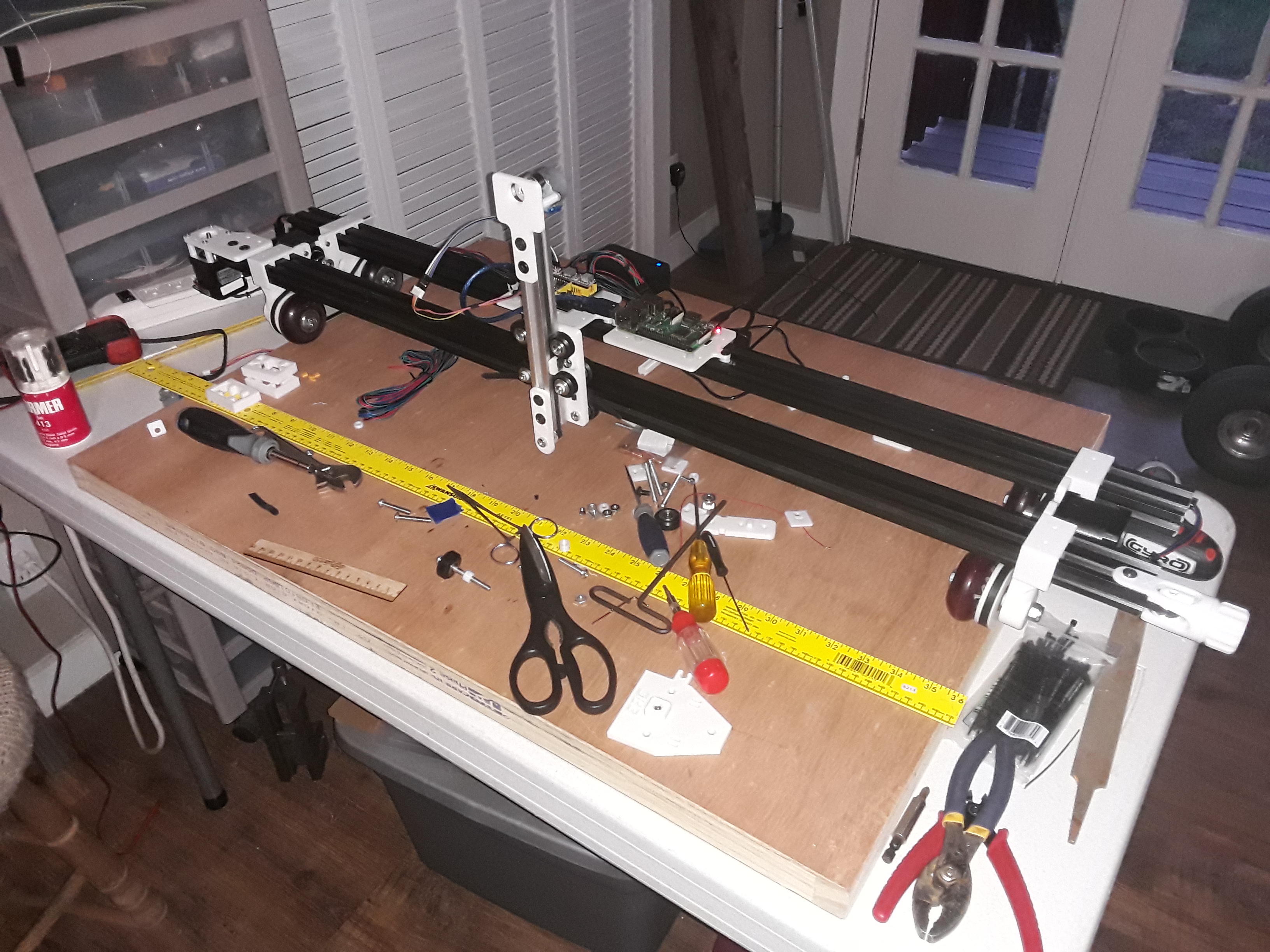
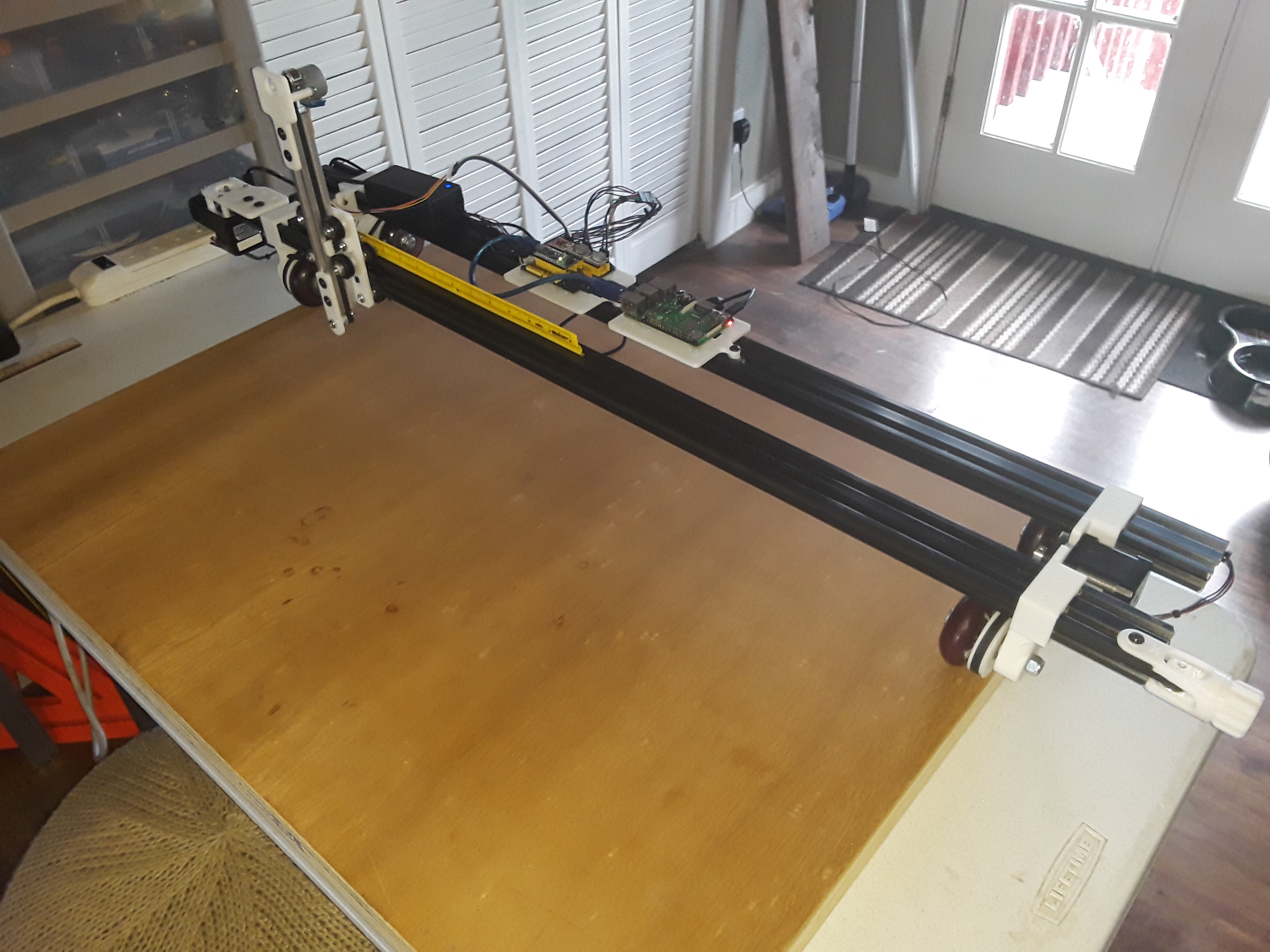
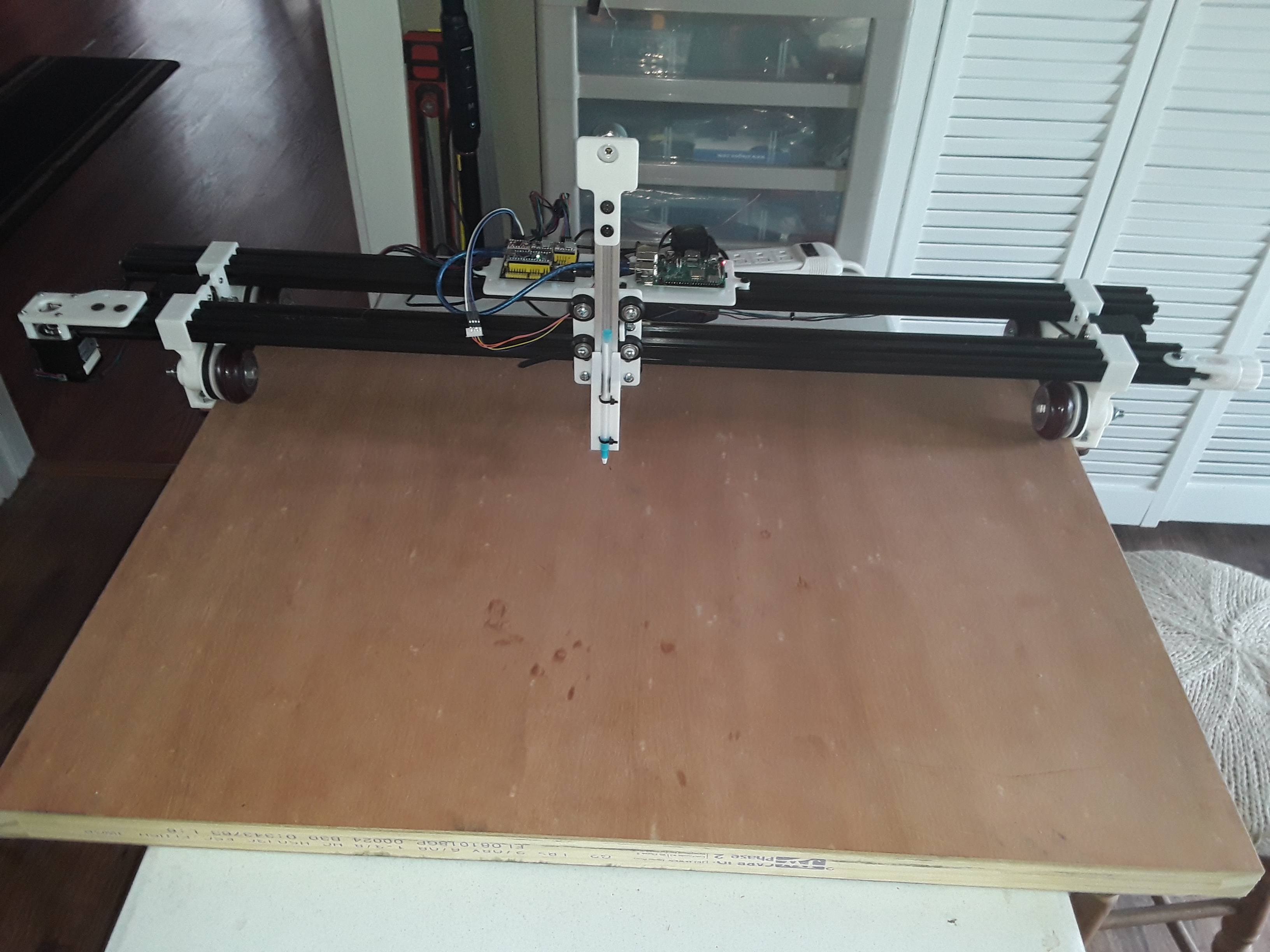
And finally, the entire 3-axis machine, sitting on the cluttered work bench…
I’m pretty sure I’ll have to have a guide of some sort to keep the wheels tracking in a straight line… I noted a little drift in some earlier “to & fro” tests. Maybe just “fender skirts” or “curb feelers”, attached to the axles on both ends, and extending slightly below the work surface… and the tractor-to-tractor spacing adjusted accordingly.
I’ll need to adapt a pen-holder to attach to the Z-axis and hopefully start running a few tests. I’ll start first with the obligatory MPCNC crown and hopefully then a few of Jamie’s rulers. It’s been a fun build.
– David
2 Likes
Looks like it is coming along nicely. I need to do that mod to the 28BYJ-48 stepper motor to have decent Z-axis. I am not crazy about the servo z I have & I can’t use it with a Marlin setup. I better get cracking on finishing my latest changes. I have a raspberry pi enclosure that gives more cover to the pi if you want to try it. I remixed from 1 or more sources. Not sure I ever uploaded it to thingiverse. Here is what it looks like. Think this works with a pi 3 or 2.
1 Like
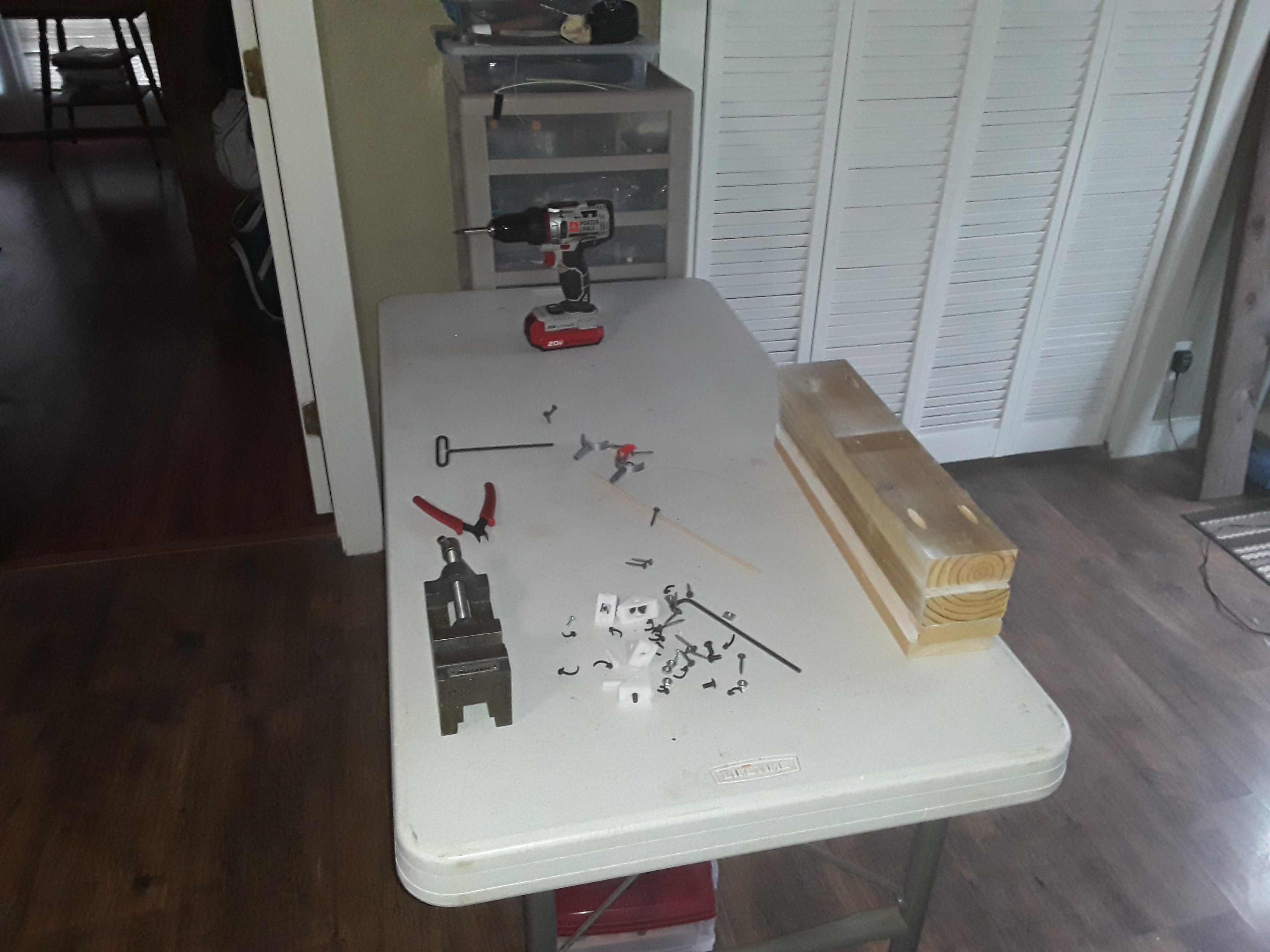
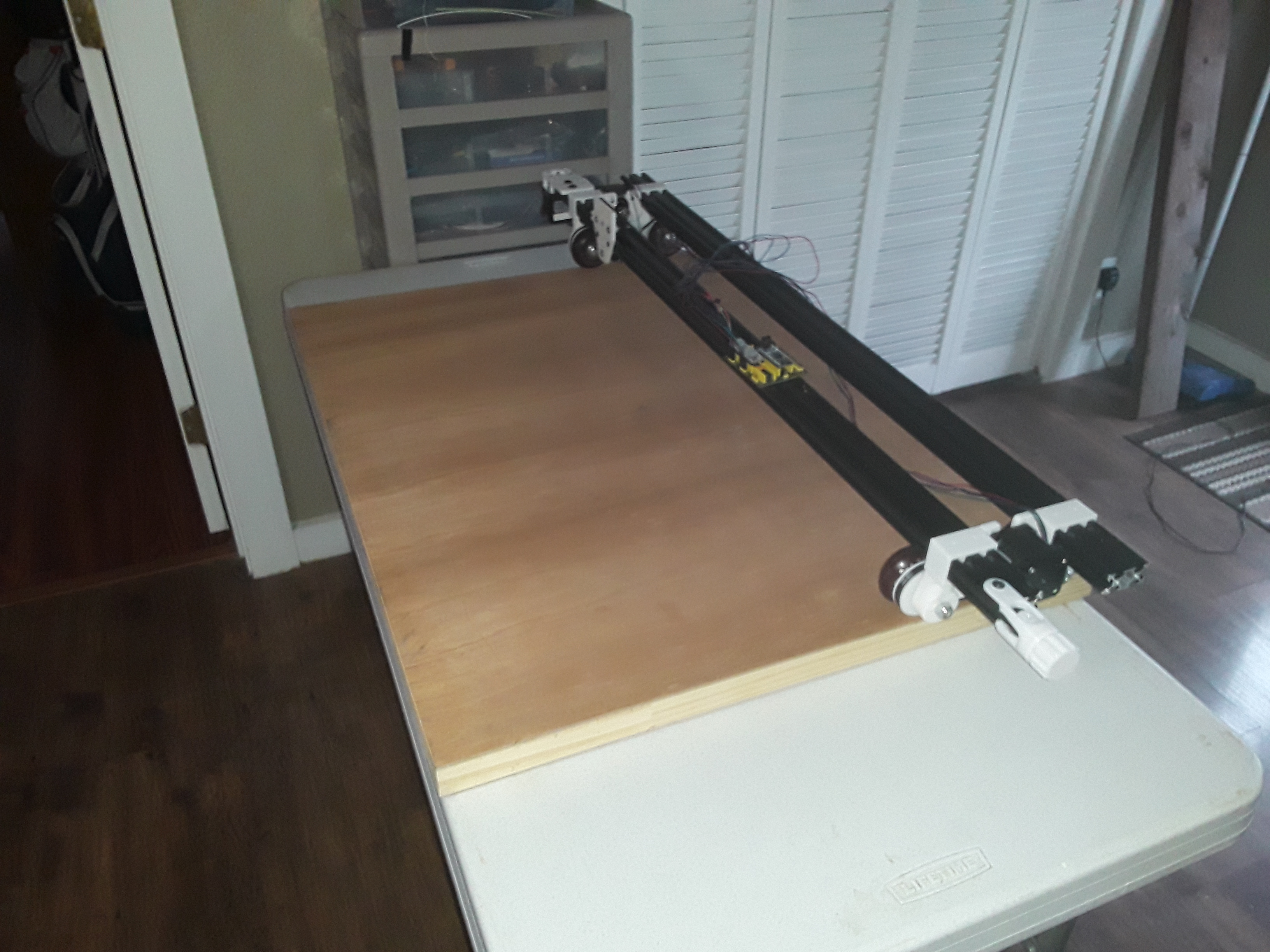
Finally cleared off the work surface and verified all axes were moving properly and in the right directions.
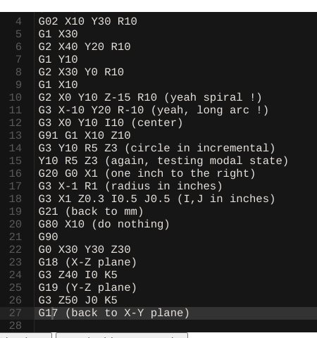
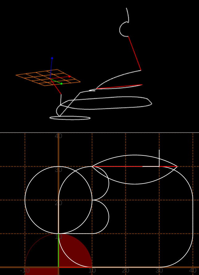
I then tested the rolling plotter/gantry with a 3D test of all axes. I used the default code snippet from this Gcode Simulator and, with only very minor changes, was able to run it successfully on this GRBL machine. It changes from metric (mm) to imperial (inch) and and back in mid-stream and even changes planes (X-Y, X-Z, and Y-Z) before returning to starting point.
Here are screenshots of the code snippet and path…
Onward to the crown!
– David
1 Like
That makes some interesting noises.
1 Like
Alright! Made a pen holder to fit my Z-axis…

And printed the MPCNC crown. This was my first attempt and the machine was just free-rolling without guides of any sort. There is “drift” as the tractors make their way, to and fro, and the closed shapes… well, they didn’t close ![]()
So I added a guide rail on the side toward where the machine was drifting and repeated the test…

This time the gap between closed-shape start and end points was much smaller… but still not perfect
I’ll continue to play with it and see what I can see…
Later.
– David
3 Likes
That is pretty close for the 2nd run. I have my new wheels & endplates printed & will test mine today. I may have to reprint the endplates with a higher infill using PLA+ instead of PETG, but maybe rigid enough after assembled.
That is an interesting way to do it. I have one more wheel to print before my next test. Have to wait for thunderstorms to pass thru first.
1 Like
With training wheels in place, I plotted the crown again. It’s “nice”… but not perfect.
Thinking initially it was probably just the dog demanding my attention… I finally came to my senses and decided to look further for sources of slop. Started wiggling the gantry around and it’s immediately apparent that I need the usual eccentric spacers (that I conveniently left out) to snug things up…
Overall, I’m pleased with the smooth operation of the entirely belt-driven gantry… just need to tighten things up a bit and I think it’ll be a decent enough gantry for plotting and laser engraving.
Now to fire up Onshape and print some eccentric spacers I found on Thingiverse…
Later.
– David
Don’t think I have heard of using 3d printed eccentric spacers before. Will be interested in seeing how those work. After your comment on the loose gantry, I checked mine. My eccentrics are good, but the vertical pen mount I only had 1 screw with t-nut on each side & it could move if I tugged on it some, so I added another screw on each side. I decided the part so it could take 2 screws on each side, but thought 1 was enough. I would like to get the belt on the carriage axis a little tighter, but it is probably ok.
How do people live in today’s world without a 3dPrinter?? 
Or gasp only one 3D printer?
1 Like
If my house was burning [heaven forbid!] and I could save just one machine out of the 7-8 machines currently sitting in my little house… it would be the 3d printer. With that one machine I can rebuild all the rest… but the same could not be said of any other machine. I have 3 operational printers right now… one is simply a pain to use (I’m considering dismantling it…) and the other two are Prusa’s, one of which is currently farmed out to daughter and SIL. So I get by with just one printer nowadays and once I get past a new machine’s basic construction it’s… [wait for it!]… spacers, Spacers, SPACERS!! 


2 Likes