Ok, thanks for the info. I have been looking some, but haven’t found exactly what I need yet. The info will show up when I need it. I am just glad you brought up the 3.3v for it, so that didn’t take me by surprise or accidentally hook it to the 5v line. Looking around at boards today, I noticed the xPro CNC v4 board actually has a variable voltage for the PWM, 0-5v or 0-10v. That is a lot more of a board than I need though & 3x the cost of my laser.
I don’t KNOW if the NEJE’s actually require a 3v3 PWM, some uP’s are 5v tolerant…some aren’t. All I can say is NEJE specs the pwm to 3v3 and as the laser modules cost folding money and the level shifters cost peanuts I have always used a level shifter…it’s 4 wires and a bit of bluetack.
Would a buck converter do the same thing? Here is one that goes 4.75V-12V to 3.3V Voltage. I probably would not buy from here, but found this link 1st.
https://www.amazon.com/Icstation-AMS1117-3-3-Voltage-Regulator-4-75V-12V/dp/B01N1I1LXH?ref_=fsclp_pl_dp_1
I wouldn’t expect it to work. It will be too slow.
A voltage divider probably would.
Or a lot of people just put a resistor in series to go from 5V to 3.3V. The principle there is that you’re feeding it 5V, but the resistor limits the current enough that nothing breaks.
Buck converters are usually for dropping DC supply voltages down to a lower value. Not usually used for signal handling…
I’m probably all wet but IIRC it’ll depend on the laser’s PWM input components as to whether the series resistor really works or not. If the PWM input impedance is very high, as I would expect it to be, I would think there’s so little current drawn that the resistor really doesn’t have an effect. The voltage divider should work but the level shifter/converter Mike suggested would be best IMHO.
Just thinking out loud – and embarrassed to show how little I know/remember – I know 1.7V difference between 5V and 3.3V seems awfully small (though %-wise it’s pretty substantial) – and I can’t remember any electronic components I ever worked with that couldn’t/wouldn’t handle that little bit of an over-voltage – so I doubt you’d blow anything up. But if 5V PWM was fed to the 3.3V PWM input, not voltage-limited, and is somehow compared against an internal Vref to determine the laser current… I can see that the might be cause for the laser not to operate properly, if the circuitry hasn’t been designed to protect itself and limit the diode current.
I saw these and couldn’t resist…
Holy hand grenade…
Killer rabbit…
A grouping for the fun-loving among us…
– David
I don’t know anything about PWM, so will take yours & Mike’s advice on this. From Mike’s comment, it sounds like he was not sure that laser used 3.3v or 5v for the PWM. How can one know what voltage it is looking for? Is 3.3v safer to use to start with than 5v if it is unknown? Not having the laser in hand yet, I am just stabbing in the dark.
From the Arduino website…
“Pulse Width Modulation, or PWM, is a technique for getting analog results with digital means. Digital control is used to create a square wave, a signal switched between on and off. This on-off pattern can simulate voltages in between full on (5 Volts) and off (0 Volts) by changing the portion of the time the signal spends on versus the time that the signal spends off. The duration of “on time” is called the pulse width. To get varying analog values, you change, or modulate, that pulse width. If you repeat this on-off pattern fast enough with an LED for example, the result is as if the signal is a steady voltage between 0 and 5v controlling the brightness of the LED.”
Our “problem” here is that this PWM signal commonly comes in 12V, 5V, and now 3.3V flavors… and it’s often difficult to know exactly which one your particular laser module is looking for. When connected to the laser’s PWM input, the laser’s controller “sees” the average voltage level (Vavg ) and adjusts the laser power accordingly. But if we hook a PWM signal with Vavg ranging from 0V to 12V to a laser looking for 0V to 5V (or 0V to 3.3V)… it could be destructive, depending on whether the laser module is designed to protect itself against over-voltage. Going the other direction (lesser to greater) won’t be destructive but the supplied PWM signal’s voltage levels really needs to match what the laser module is designed for… for all to operate properly.
The following series of scope photos show a +5V PWM (variable duty cycle) signal in response to the particular gcode that commanded it… here, Marlin’s D9 fan control signal, M106 (S-value ranges 0 to 255). Note the repeating signal, triggered on a rising edge, switching between 0V (OFF) and +5V (ON), and the duty cycle is the ratio of “time ON to total PERIOD” (one period is time from rising edge to rising edge)…
M106 S127 is half-power and, as expected, we see a 50% duty cycle, and Vavg = ~ 2.5v
M106 S64 is quarter-power, 25% duty cycle, and Vavg = ~ 1.25v
M106 S0 turns the laser off, 0% duty cycle, and Vavg = ~ 0v
M106 S192 is three-quarters power, 75% duty cycle, and Vavg = ~ 3.75v
and, finally, M106 S255 is full-power, 100% duty cycle, and Vavg = ~ 5v
Maybe more than you wanted to know… but I hope this helps.
– David
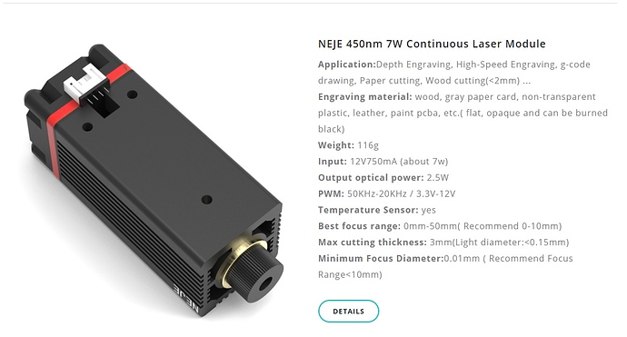
As usual, NEJE is a Chinese company that releases specs for their products that are, at best, confusing, and at worst, wrong.
Clearly states PWM: 50kHz-20kHz / 3v3 - 12v
Although I am not impressed with the 50kHz - 20kHz figures…it makes me thing they have got that wrong and maybe it should be 5kHz - 20kHz, but the 3v3 - 12v would indicate to me that a 12v PWM signal will be OK…but again, I don’t trust it, don’t forget the laser is running off a 12v supply and the Chinese love to ‘lose things in the translation’. (to put it politely.)
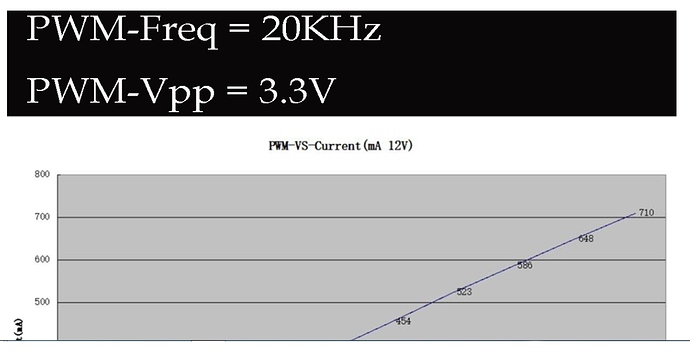
In the details page they print this -
clearly showing the output power reaching it’s theoretical maximum with a 20kHz 3v3 PWM signal and a 12V supply.
At the end of the day it’s your laser and you can feed it with whatever you like!
Sorry Dave but I disagree with you about the Vavg… the input to the laser will be some form of FET and it is only interested in the time its gate voltage passes it’s gate/source voltage, not the level of that voltage…it does not behave like a transistor, it behaves more like a switch, switching on when the gate voltage is above Vgs and off when the voltage drops to zero so it follows the duty cycle switching the laser diode on and off at whatever the PWM frequency is. some FET’s have a very low tolerance to it’s gate voltage, certainly less than 12 V, much closer to maybe 4V, and some FETS will tolerate a higher gate voltage and unless you know the specs for the actual FET used you are risking blowing it if you feed it with too higher voltage.
Your Vavg is certainly measurable and has significance in an analogue circuit…but not in this application.
Thanks for the detailed info @dkj4linux & @dart1280. Maybe I will order some of those level shifters Mike mentioned before testing that laser. Are these on Amazon about the same thing. I could get them a lot quicker than the ones from China for $7.29 for a short wait instead $3.60 for long wait.
Thanks for the clarification, Mike. I can see what you are saying about the FET input acting as a switch and simply responding to the time HIGH. The question is then… how HIGH is too HIGH? I didn’t actually say it but I think I implied it… we don’t (at least I don’t…) know how well designed and robust/tolerant the circuitry on a cheap import laser. Chances are they are very cheaply made, with the bare minimum circuitry necessary to do the job… so there is certainly the risk of over-volting them when we don’t know exactly what levels they are designed for. That is one reason I keep using the Eleksmaker lasers. I’ve learned from experience their “TTL”-level PWM is +5V PWM… so I’m not having to guess, and they’ve always worked nicely for me.
I have a request for you. Since your grand-daughter is so good at sketching this type of art work, I was wondering if she could sketch something like a squirrel driving a train? That might be a good test chalk drawing for my rolling plotter. We have a lot of white squirrels in our town & they are actually protected & the town just built this nice train depot on Railroad Avenue. My wife thought something like a squirrel driving a train might be a good test plot on the sidewalk beside the train station. She should also put her initials or signature in the design somewhere. I would give her credit for the drawing if anyone asks about the artist. I would ask the Mayor before testing it there though since that train depot was his pet project. I have some GT2 belt coming in today so I can finally make my rolling plotter 1 meter wide. Anyway, just thought I would ask if she feels inspired to do this.
Yes Dave…those are the same.
I also suspect your assessment of the circuitry inside one of these laser modules will be on the ‘economical’ side  in fact, if you take a look inside your NEJE laser (the one that stopped working) I think you might wonder where the rest of the control circuitry is!!
Have you ever tried laser etching photos on eggs?
No, I haven’t. I’ve threatened, over the years, to build an Eggbot and a rotary axis but, always resisted… telling that part of me to “go away… I don’t like being bullied.” 
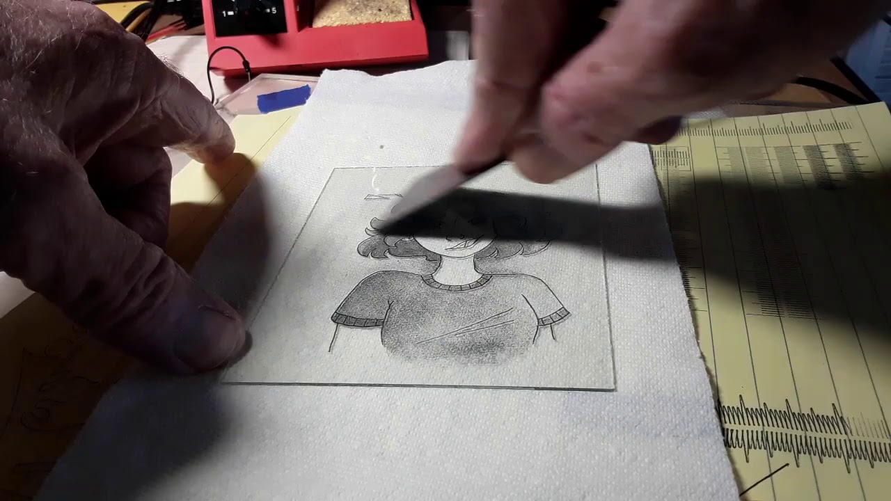
I’m more likely to entertain that now, living in proximity to some of my grandkids. I’ve also confirmed that the white tile etching method also works on plain glass… so am positive you could etch mugs, glasses, etc…
It works on plain glass as well?? I’m sold! Can we see up against the light?
I’m curious, when glass (or tile) is lasered, does it affect the surface texture or is the image below the surface?
It leaves a hard, slightly raised, texture on the glass… where the paint/glass are hit with the laser
This is all done with a simple little 2.5W diode laser. The glass is first coated with a light coat of flat white spray paint, allowed to dry, the image is lasered, and the paint remove with thinner or acetone.


