The issue is having the Z nut make contact with the coupler. That means the T8 has to be perfectly inline…this would be easy if we could tighten the tension screw at the bottom of travel. Instead, we have to snug it up, test up and down motion for binding and adjust if this is any. All of this is simple…but it is another step, and for the beginner having the two disconnected is failsafe as well.
1 Like

1 Like
I just homed the axis’es er axis’ er axii er axiis er axes, the FRONT BACK LEFT RIGHT UP DOWN things! Feeling awesome!!!
4 Likes
I have them installed on mine. Loosely, but installed. My prints have enough tolerance in the holes to allow it to move within the slot easily, and the nuts are not tight.
1 Like
Okay, let me specify: I’ve never seen anyone use them that actually needed them. ![]()
1 Like
Maybe also add a brief reason on why it’s designed there and why the builder would most likely not need it.
Once I got the whole unit assembled this evening I saw how it is a good failsafe implementation, but for some reason wasn’t obvious while I was building it.
I just surfaced my table and I think I found a need for them with a 1/2" dovetail at 100mm/s.
agreed
3 Likes
This new machine is fantastic! This morning I did 2 more tasks.
-
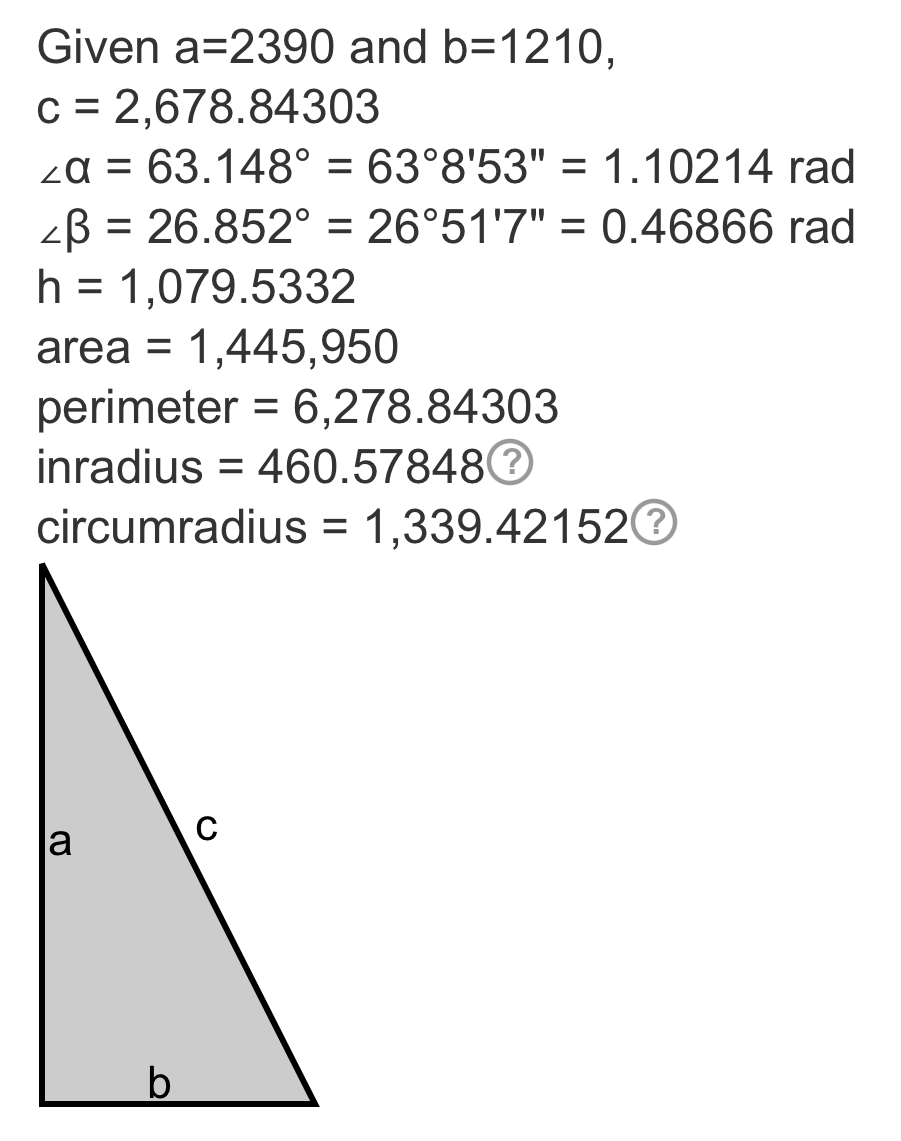
I checked belt accuracy, using the v-bit and painters tape method. Sent it 2390mm with the terminal then measured the pinholes and came up 2391mm. Not bad!
-
Next I checked corner to corner. Punched pin holes in at x10y10, x1220y10, x1220y2400 and x10y2400 and my corner measurements came out 2678 and 2680mm. This blew my mind how close it was!
Ryan, you (and all your testers/collaborators) created something amazing here! I think I’m more giddy with excitement for this machine than when I finished my MPCNC Primo!
I also figured out how to switch to (and back) to STA mode. Very cool!
I do have a question though…
- As I found that I was traveling 1mm to far over 2390mm on the Y axis I used the equation in the build notes and changed my steps_per_mm from 50 to 49.979 for both X and Y. I did this in web UI, hit save and sent the restart command. Check to make sure it changed and it stayed 50 in both places. So I tried it again a couple times with no change. Any suggestions? Should I change it in the config.yaml on the computer and then import it with WebUI or do I do that with FluidNC Web Installer and a USB cord?
1 Like
You need to use my save macro, or edit your config and transfer it back.
So I make the changes, save at the bottom of the settings screen, the on the home screen use the save macro, reboot. (I don’t actually think you need to reboot, but it makes sure you really saved it.)
1 Like
Cool, thanks!!
This is it for building machines for me for a while. Now I’m going to throw myself into making stuff with my two V1 CNC’s.
I am going to build ZenXY but I consider that to be creative thing (even if is a machine). I’m going to use the LR4 to make the table. I have this antique mill/drill that I’m going to cut off at bar table height and make that base for ZenXY table.
4 Likes
By home screen, are talking the dashboard?
1 Like
I’m an idiot! It was right in front of my face!!

3 Likes
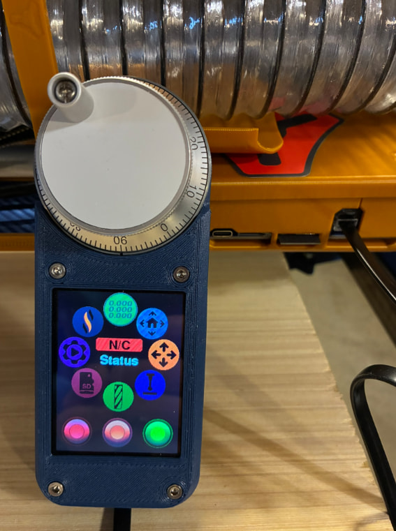
Wow impressive looking rig!
Thanks Doug!
Okay, I know I’m putting the cart before the horse and steering him right off of the YBR on top of it, but if anyone could tell me what I’m doing wrong with enabling this pendant, I’d be so grateful…
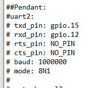
I downloaded the JP3_LR from Github and found this commented out at the bottom of the config.yaml…
So I tried enabling those settings through the FluidNC Web Installer…
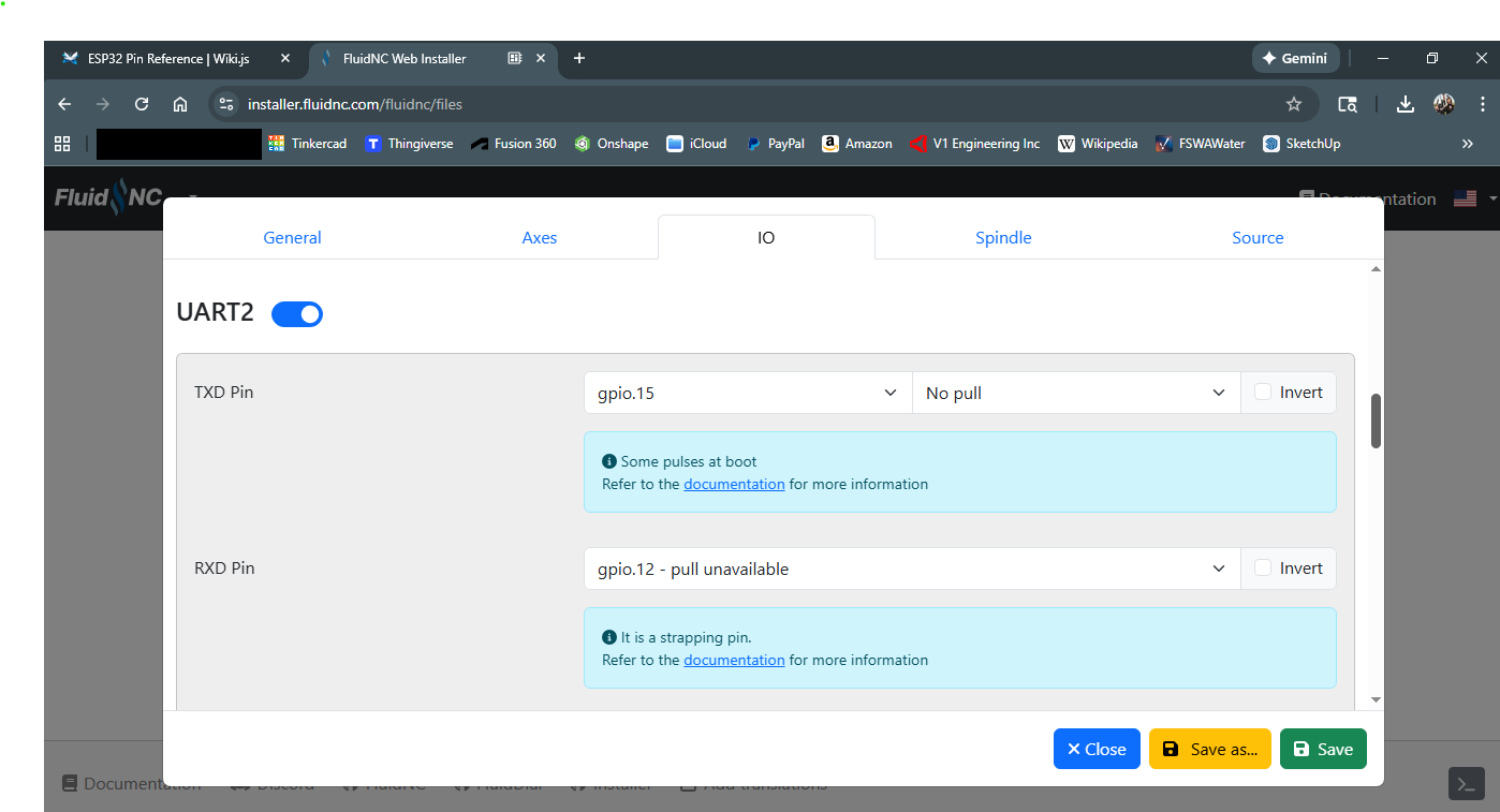
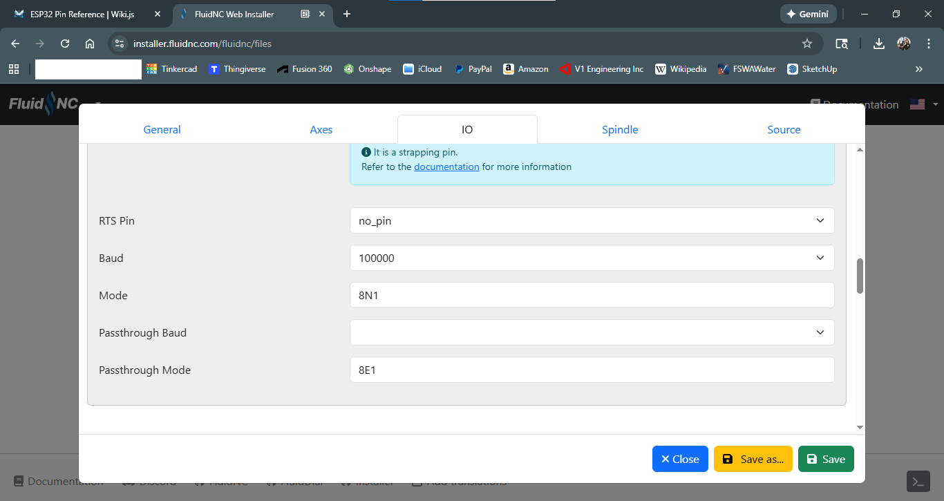
Which then showed up in the source file…
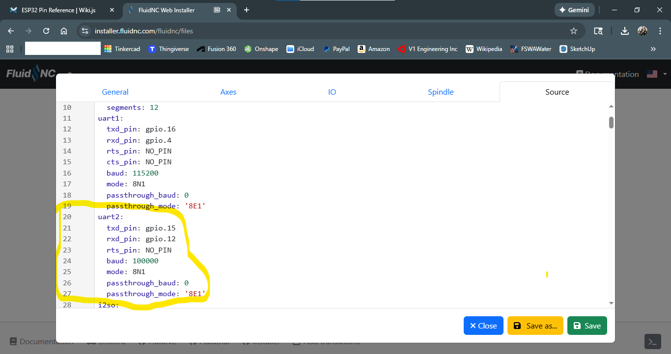
But still no connection?!
Any thoughts?
1 Like
Yours looks different than what I see here…
##Pendant:
#uart2:
# txd_pin: gpio.15
# rxd_pin: gpio.12
# rts_pin: NO_PIN
# cts_pin: NO_PIN
# baud: 1000000
# mode: 8N1
#
#uart_channel2:
# report_interval_ms: 75
# uart_num: 2
I would use a text editor, you will need to disable (NO_PIN) the other place that shows pin 12 and 15. If I am not mistaken.
That web tool is best for an initial set up but have already taken care of that for you.
1 Like
This is from my JP3 config:
uart2:
  txd_pin: gpio.15
  rxd_pin: gpio.12
  rts_pin: NO_PIN
  cts_pin: NO_PIN
  baud: 1000000
  mode: 8N1

uart_channel2:
  report_interval_ms: 75
  uart_num: 2
1 Like