Thanks. I still am a big fan of your work and videos. In the long run, it’s likely better if I build my LR4 3D mock-up model myself anyway.
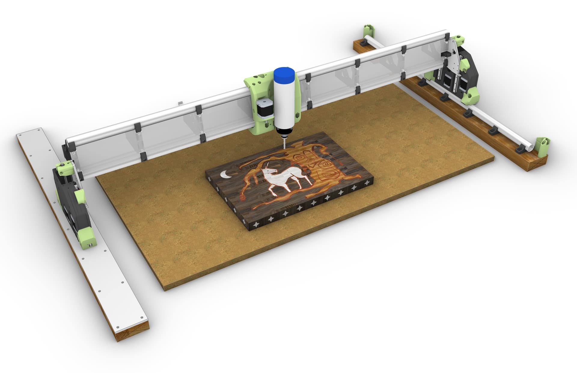
I’ve decided to keep the X and Y axis as stock and to make the Gantry on my 2’x4’ table as the 4’ dimension. IE: X = 48” and Y = 24” work area. I mean, this is a full sheet capable machine, so having a 4’ gantry is or can be considered “normal”
The bonus is that the homing position is standard and consistent with my Primo Build, and there will be no obstruction on the table at the front where I have a cut-out in the table to do vertical work mounting.
I also want to design a pseudo Z-independent dust shoe since I’ve gotten used to having one on the Primo.
In general, I’ve been inspired by Marius Hornberger’s Z-Independent dust shoe on his CNC:
And even though on the LR4 the whole gantry goes up and down, I want to design a dust shoe that maintains its z-height at the top of the workpiece (if possible) or at a minimum, use some sort of spring load z-height so that it can fluctuate up and down based on the workpiece height and tool bit depth.
So getting myself very intimate with the “stock” LR4 3D printed parts and where I can make attachments etc.
As you probably know, I did a Z independent dust shoe design for the LR3. So, I’m definitely not opposed to the idea. That said, the LR4 stock dust shoe is excellent, and since Ryan has made available both standard length TPU bristles and a LONG set of bristles, I’ve been quite happy with the new stock setup on the LR4!
Part of the “fun” for me at least, is not the final destination but the journey. So my brain is already excited about the challenge of designing a dust shoe that can go up and down independently of the gantry, which also goes up and down.
I’m already wondering if I can use the 5th stepper driver to interpret or intercept the z-axis movement and mirror them with the dust shoe. IE: when the z-axis of the spindle moves down 10mm the z-axis of the dust shoe would move up 10 mm and vice versa.
So in theory once you set the z-height of the bit IE: workpiece Z-0 that also establishes the machine coordinate z-height (whatever that number is)
In theory you could then independently raise or lower the (A) axis for the dust shoe to it’s own A0 work height. which would then be adjusted by the inverse of the new z-height as the G-code was running.
Like many things it all works “in my brain” however getting it to work outside my brain is the hard part.
If I go down that journey, I’ll post my progress, and if I get it to work, I’d be happy to share it with others.
Next steps are to dream up an independent z-height dust mounting system.
I’m thinking of a weighted dust shoe riding on stainless steel rods with a stop collar and spring so the dust shoe can go up and down mostly independently of the gantry.
It would be mounted to the gantry and go up and down with it, but the springs would allow it to go up and down based on the work material height. IE, the TPU bristles would touch the top of the workpiece, and that force would make the entire dust shoe raise up.
I would need stop collars to prevent the dust shoe from dropping too low and hitting the side of the workpiece, though.
For starters, though, I’m going to try out the stock dust shoes with variable height TPU bristles, and like Doug said, maybe I’ll just be happy with them.
Question for anyone who wants to respond:
Has anyone thought of making the end caps for the Gantry (Peter Plates) out of milled aluminum to give a bit of extra weight and some extra “Bling” to the build?
But you can very probably just run another stepper motor from Z1 or Z2 in series, and jt will always stay lockstepped to the motor that it is in series with so long as the driver is powered up it can follow forwards or reversed depending on how you wire it in series.
You probably want a forwards follow anyway, as the motor will (probably) be overhead for the dust shoe. It is under for the Z axis.
Z+ commanded pushes the nut away from the motor. On the Z axis, this raises the gantry. On the dust shoe motor, this would push dust collection downward.
Fun possibility:
configure firmware to use 3 Zaxis motors, with 3 end stops, and add a probe/switch to the dust collector motor. When you home Z, Z1 will stop at the top, Z2 will stop (level) at the top and Z3 will stop with the probed height for dust collection. Setting up the probe to be put of the way when the job is going would take some doing, maybe a servo circuit, BLTouch-like? Or maybe that’s just too much. I knkw it’s more than I want to actually do, but I enjoy working out the possibilities, so I already.had the ideas for a constant height motor drive. (I was thinking about a camera mount, for project video, not for remote monitoring.) I decided too.much trouble though, it’s not like I really want to post up a lot of project video.
That’s brilliant I had not thought about doing it this way.
Wiring a (3rd) stepper in series to the two current z steppers might just work.
Gantry goes up 10 mm (would result in the dust shoe going up also 10 mm but if it was on a stepper motor pointing down (opposite of the two gantry steppers) then it would go down 10mm essentially staying at it’s zero position at the top of the worksurface… so far so good
___
Gantry moves down 10 mm (back to endmill z-0 top of material)
Dust shoe goes up 10 mm (stays at top of worksurface) Still good
___
Gantry moves down 10mm more setting endmill 10mm below the top of the worksurface
Dust shoe moves up 10mm more (stays at top of worksurface) Still good
___
I think this might just work without any need to rework any config files etc.
For now setting the TPU bristles to top of worksurface manually and locking that in when the tool (endmill) is at working z-0 height would work without another end stop as long as whatever mechanism the dust shoe is connected to it’s stepper is adjustable and can lock into position manually then move up and down with it’s stepper after locked might just work.
Sort of like a depth gauge setting on a drill press, or plunge router.
Yes I’ve thought about this and even have the material to do it - some 5mm aluminium I got for making the strut plates but went with 3mm aluminium chequerplate instead.
it would be a double sided cut to make it work and I haven’t worked myself up to that yet.
I did add PLA plates and I like them very much.
probably higher up my list before aluminium end plates would be
Gantry covers
X axis cable anchor
After aluminium plates would be aluminium struts.
Of course none of these are in any way required, possibly not even a good idea, and everyone in every case should build fully stock first.
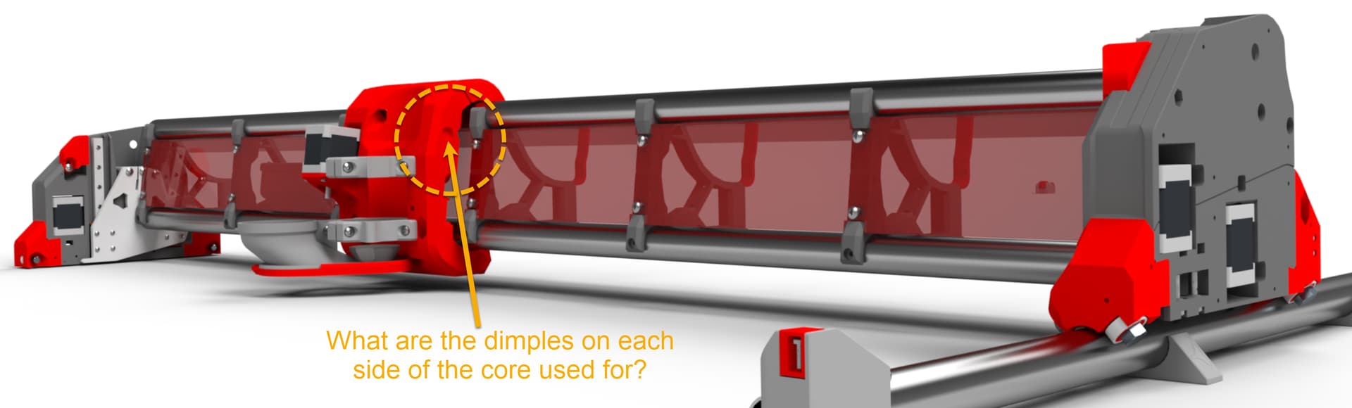
accommodation to get every bit of X travel out of the core that is possible. They are clearance for the screws that go into the XZ plates. with the V1 provided screws (and many other pan-head M5 screws) this allows the core to travel all the way to the XZ plate in both directions.
Sdries wiring can be done to slave the motors in the same, or opposite directions.
Wigh the following configuration:.
Board 1 → Motor1 1
Motor 1 2 → Motor 2 1
Motor 2 2 → board 2
Board 3 → Motor 1 3
Motor 1 4 → Motor 2 3
Motor 2 4 → Board 4
This arrangement will have both motors turning the same direction, and could be used if you only had 1 motor driver for Z on a lowrider.
If you change it like this:
Board 1 → Motor 1 1
Motor 1 2 → Motor 2 2 (Current is reversed between motors 1 and 2)
Motor 2 1 → Board 2
Board 3 → Motor 1 3
Motor 1 4 → Motor 2 3
Motor 2 4 → board 4
You will get the motors turning in opposite directions. This would work for the Y channels on a LowRider, where you need the motors to turn in opposite directions to move in the same direction. (Also for either X or Y channels on a Primo.)
Many 3D printer boards have 2 outputs for the Z motor. The SKR Pro, for example, has 2 outputs for Z already wired in series, whereas the RAMPS 1.4 board has 2 wired in parallel. You can tell series, because the second output needs jumpers if there is no motor plugged in there, whereas parallel just leaves the second port open. Series is superior for current handling, but has a lower top speed limit due to back EMF. (Not really important for Z.) Anyway with a board like the SKR Pro, zero changes are required to have a motor follow Z1, just remove the jumpers and plug a motor into the existing port. (I guess this is moot for the Jackpot which does not have this feature.)
V1 used to sell harnesses for doing series connections, but they would be wired like the second example, with the second motor following in reverse (Used for the X/Y motors on a Primo.) I don’t think they’re in the store anymore, but they’re not difficult to do, just need some wire crimping. I think I actually have a couple around somewhere, but I never used them.
You can’t run it in series with both motors. You can drive it from one of them. There are some small caveats when you do that. If you run them in parallel, the current gets split between them. We don’t do that anymore. If you run them in series, the reverse voltage that happens when they speed up increases. Most people get this effect wrong. But the summary is that it would reduce your top speed (rpm) for that Z motor. You can increase the top speed by increasing the supply voltage and 24V should be enough for reasonable speeds.
You can also configure another driver to make the 6th slot mirror one of the Z motors. An extra driver and a few minutes of config file and you have cleaner wiring, and neither of these downsides.
Either way, you will want to be able to set the height of the dust shoe. When you home the Z, both ends will travel up to their respective endstops. The motor you tie to this dust shoe will move up to its endstop. Then go back down to reach a touchplate when you do the probe. The dust shoe will need to be at the correct height before all of that because there is no way to disable that motor after that. You can just set the dust shoe height before powering on the machine. Then it needs to be capable of moving through the entire range of motion of Z during that homing process. If you don’t like that solution, then you need some way of disengaging the shoe from the motor and adjusting the height while the Z motor is holding.
Based on a completely different project I had at one point, I used a stall as a simple homing method. Not super accurate, but was plenty for that situation.
If he ran it off a separate driver, then after a probe, he used a stall to find the reference position of the shoe, could he then automatically lower it to a position to create the height he wanted? (i.e. assuming a fixed position of something like 20mm above the workpiece was optimal.). There’d have to be math to create an offset between the tip of the tool and the stall/home point of the shoe. Just an idea.
For the record - yes, I’ve cut Peter plates from Al but haven’t installed them yet. They were sort of test cuts prior to my Al struts.
Also for the record - I’ve printed a couple of dust shoes for my spindle and have just changed the length on the TPU bristles. If I’m using a tool that needs longer bristles for dust collection I just swap them out. I’m wondering how much weight the floating Z will add but watching the project with interest!
I definitely stalled a lead screw based system. It was a “pebble wiper” on a toolchanger. The toolhead moved to it, then it moved up under for the pebble extrusion. Homing was a simple stall. If I recall, you can set the parameters and I’m pretty sure it was a current based stall detection. (The toolchanger doesn’t exist anymore or I’d check. ) Because the position didn’t need submillimeter precision, I set pretty sensitive parameters.
It looks like the TMC2209 reports on the DIAG pin.
Anyway - the main problem I’ve been chewing on (while cleaning and unpacking) is that you’d want independent control until the height had been properly set, then you’d need to redefine it as an inverse of X? I’m not sure this is possible. At least I’ve never seen anything like it.
The firnware doesn’t understand how to use that in this case though. Trying to make a simple dust shoe wouldn’t work well with that diag pin/stallguard.