Hello,
Does anyone have assembled model of Lowrider v4, im starting the build but it would be way easier if I have assembled lowrider model.
Also im planning to build metal frame for table and then just screw panels on frame.
Hello! Ryan has not ever released one on the LowRider (while by contrast he has on the mostly printed printers he designed), and out of respect for him, those of us that build our own “complete” model, by dropping the printable files into a 3D space, refrain from sharing them.
4 Likes
Just follow the assembly docs, they are pretty good and well explained with a ton of pictures. I seriously doubt you will need anything else for you to assemble your machine. Here’s the instructions: INSTRUCTIONS
2 Likes
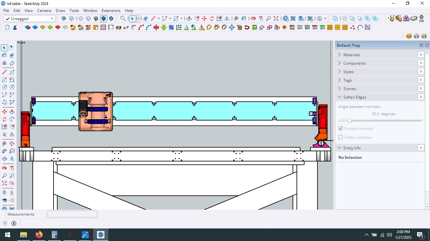
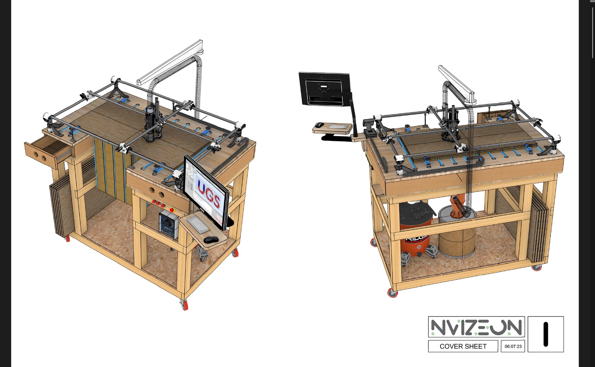
Today i have finished my complete model, i ![]() my computer was going to explode, it felt sluggish as hell
my computer was going to explode, it felt sluggish as hell
2 Likes
Same to me, I do it in Fusion and I never open the file again because it takes about 5 minutes to open ![]()
1 Like
For what it’s worth, my approach to alleviate that kind of issue is to bear in mind that the mesh complexity of the final models used for printing is, in many cases, far more detail than is needed for a functional mock-up, so I have used the mesh reduction feature in the Fusion 360 to reduce how many polygons there are, I have saved these reduced-polygon count models just for mock up use. Because I do some of my modeling in Fusion, and some in SketchUp, having it saved/exported allows me to then import the reduced polygon count models into a mock-up in SketchUp.
2 Likes
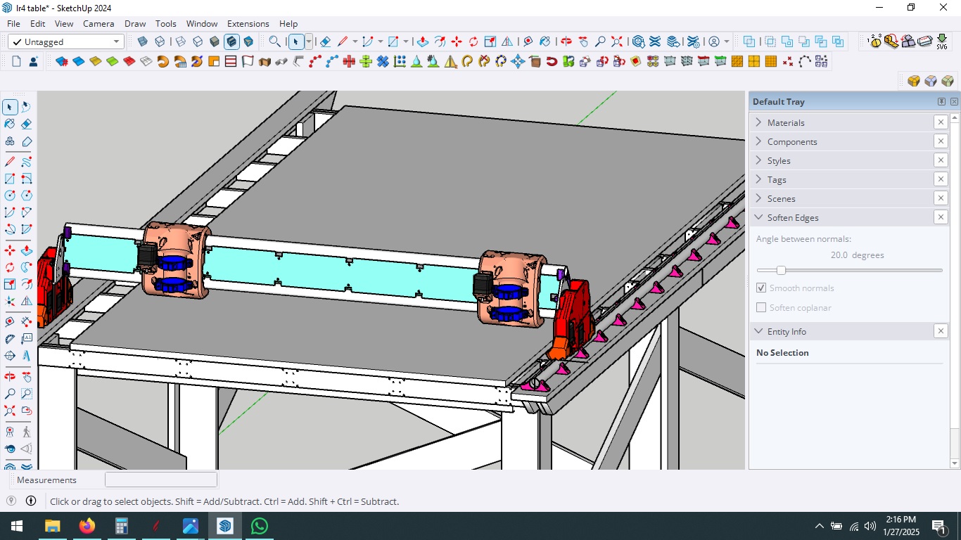
yes i did simply soften the stls. with just a little patience it can be done. ( i did not use all the parts really just the main ones) whats difficult with this approach is to align the beam with each y plate to be in level.
btw, im doing this to see everything before i start making a 3rd (4th more really, idex) Lr4
3 Likes
Doug
I’m a big fan of your videos and your overall approach to CNC etc.
I’m going to be switching from the Primo to the LR4 soon (ish)
I’ll be switching the X and Y axis, just as you have, and your Config.yaml file will be invaluable.
Since you have already made a completely assembled LR4 in Fusion and in Sketchup could I ask a favor and have you send me the files.
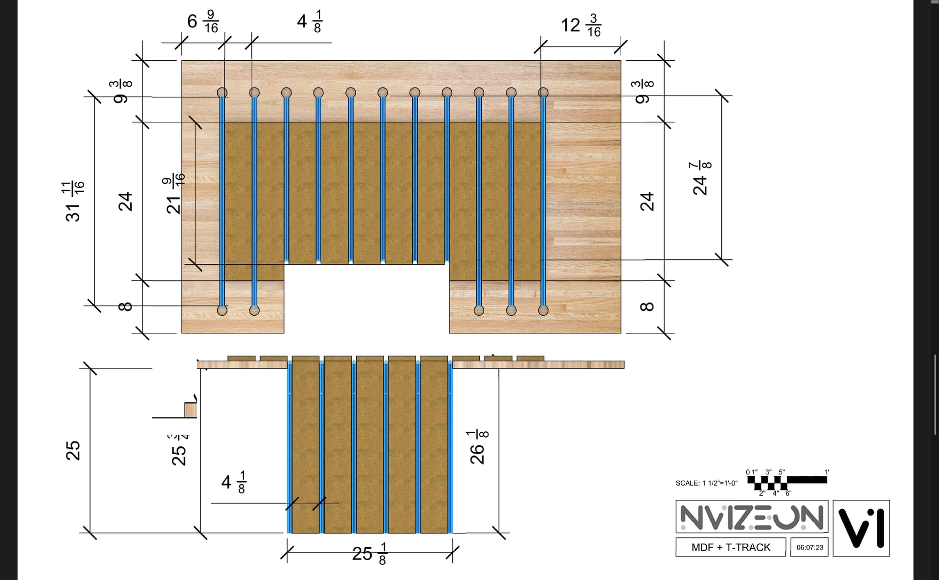
My issue is I already have the Primo table setup with T-Track and replaceable MDF spoilboard strips between the T-Tracks.
I want to position the Y-Rail and mounting brackets in a specific location on my existing spoilboard, and a completed 3D model will help me dial in the specific (Gantry Length) to position the rail and the opposite side rollers.
I can, of course, dump the STL’s into Rhino 3D and build my own completed model, but if I can save the time by borrowing yours, that would be helpful.
1 Like
I think he’s already answered this:
2 Likes
Thanks
Yes, I saw that response …but you can’t blame me for trying anyway.
In general, since this is a “community” forum, sharing stuff is what we do.
1 Like
This IS a community, and we share quite a bit…
but this is one of those areas, like some others, where we tend not to cross the line out of respect for Ryan, as noted above.
2 Likes
Hey @Nvizeon, I don’t blame you, it’s a fair question. I appreciate the responses you’re seeing too.
Are you wanting the full model to help you figure out how to plan your table and setup? Would dimensions be enough for this task?
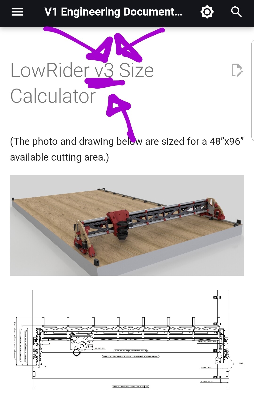
Previous LR3 calculator included a dimensioned sketch, see LowRider V3 Calculator - V1 Engineering Documentation , I haven’t seen one for LR4, would that have been helpful, and good enough?
2 Likes
Yes precisely!
I want to position the “y” Rails and rollers to avoid the recessed T-Track slots in my spoil board
The LR4 Calculator states this”
“Table Size
This output is the minimum table required - belt holders will be installed flush with the outside corners. An extra 25-50mm (1”-2”) or more on each dimension is nice if you will be pushing it up against a wall or in a corner and to provide some protection for the belt holders.
But I’m looking for a bit mor precision in placing the mounting brackets etc.
2 Likes
Drop table! It will be interesting to keep following along with that.
3 Likes
Well, it’s likely a good thing for me to make a completely new assembled 3d Model of the LR4 anyway, since I’m planning to swap the x and y axis, and I am using a 1.5KW spindle and using Proximity switches. I also want to design and print a z-independent dust shoe anyway ….
So there are going to be a fair number of “mods” I need to design and print anyway.
Having an assembled 3d model helps facilitate the modification process IMHO.
Oh well, I guess dumping STL into Rhino 3D is in my future.
I just wish the models were in Step format, so Snap points to arcs and circles were inherent in the individual components.
But beggars can’t be choosers…or so the saying goes.
1 Like
Look for the onshape parametric table shared by ryan or @Jonathjon JJ and measure the rollers spaces. Or take the spoilboard position as a reference from one corner. That should do the trick without making us break ryan license for his models
2 Likes
Look at Ryan’s new one for sure. Mine is made from the old LR3 table and not near as accurate as Ryan’s
2 Likes
Just assemble your table without the spoilboard and measure things, do a cut plan for the track holes. It will definitely be better that way
3 Likes
Thanks Cesar that is helpful.
2 Likes
Sorry for delayed response, been working an awful lot! I echo pretty much what has been relied above.
My trick of making low-polygon-count versions of the most complex parts of the Low Rider – just for planning use in a 3D model of the machine, has been a real good thing for me.