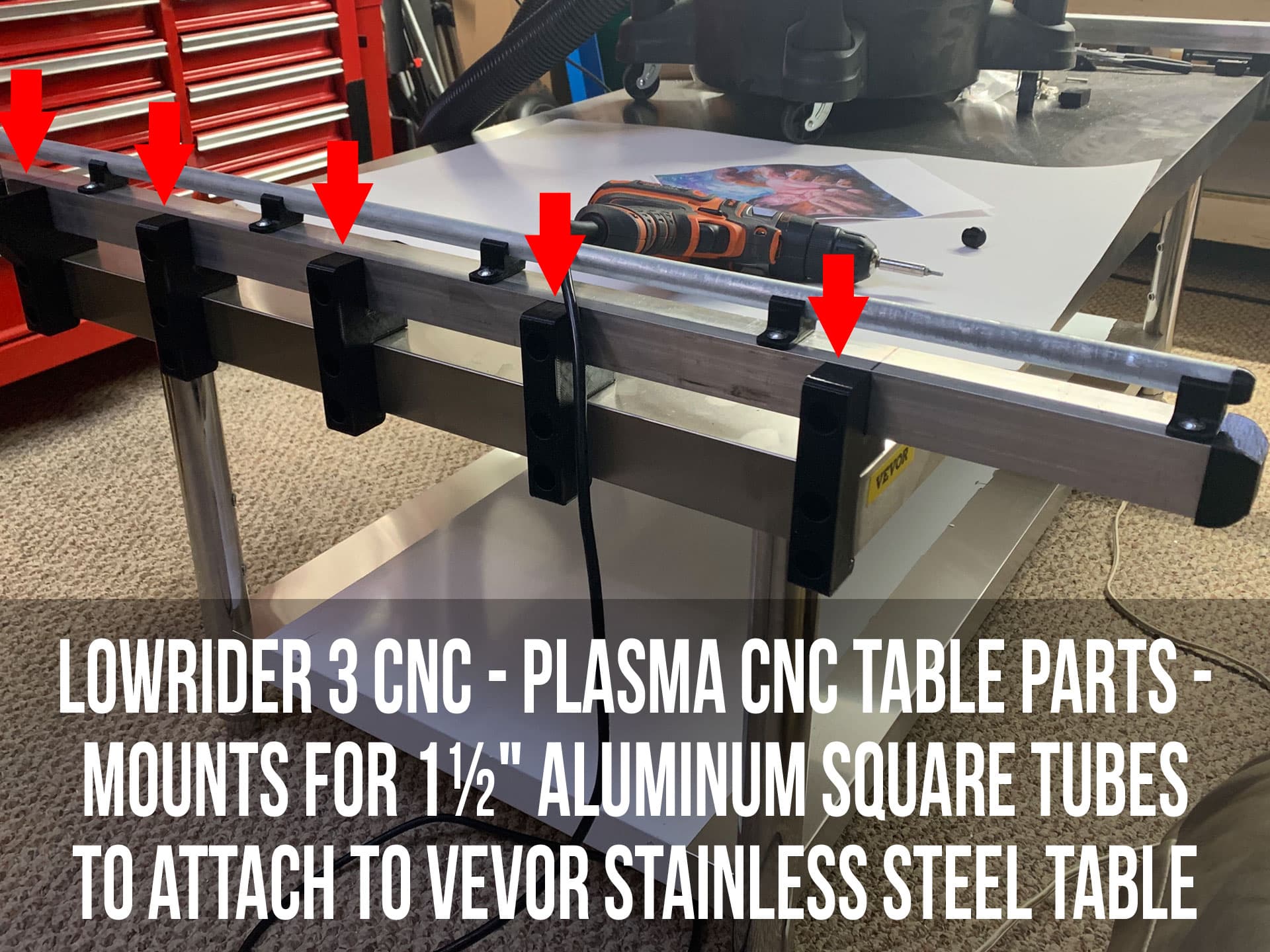
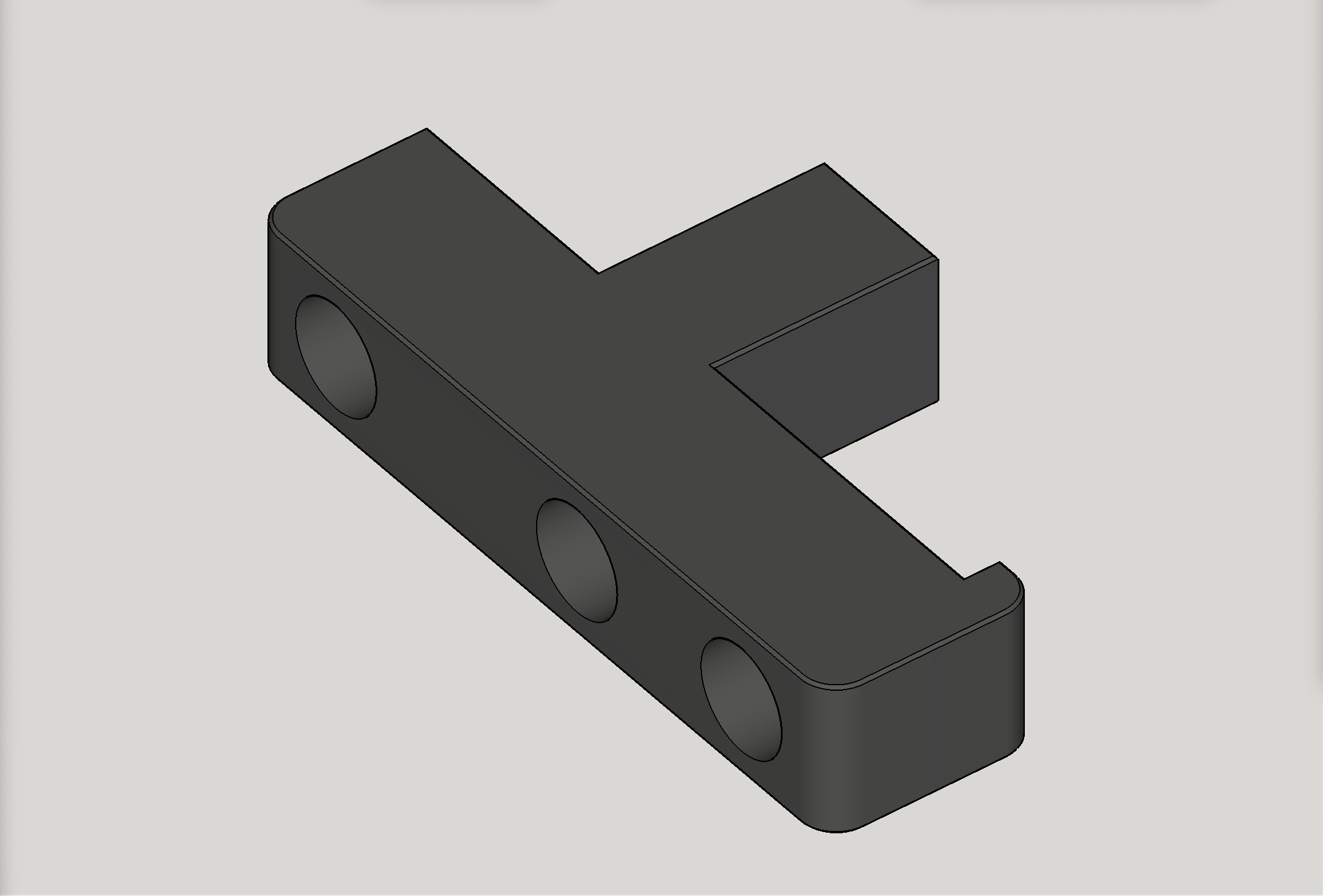
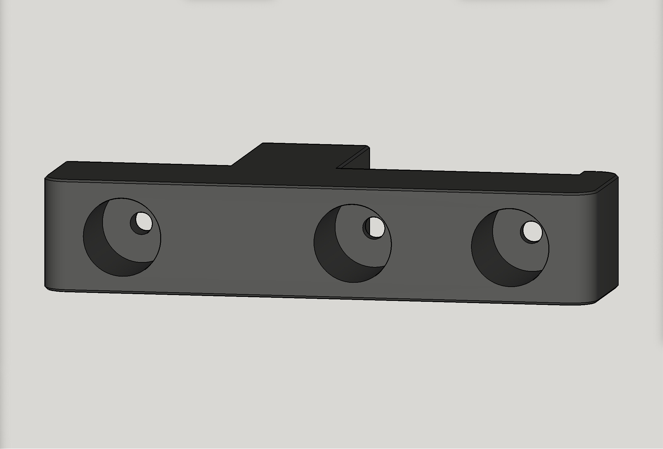
LowRider 3 CNC - Plasma CNC table parts - Mounts for 1.5-in aluminum square tubes to table
LowRider 3 CNC - Plasma CNC table parts - Mounts for 1.5-in aluminum square tubes to table by Doug Joseph (design8studio) | Download free STL model | Printables.com
The following is copied and pasted from the description on Printables:
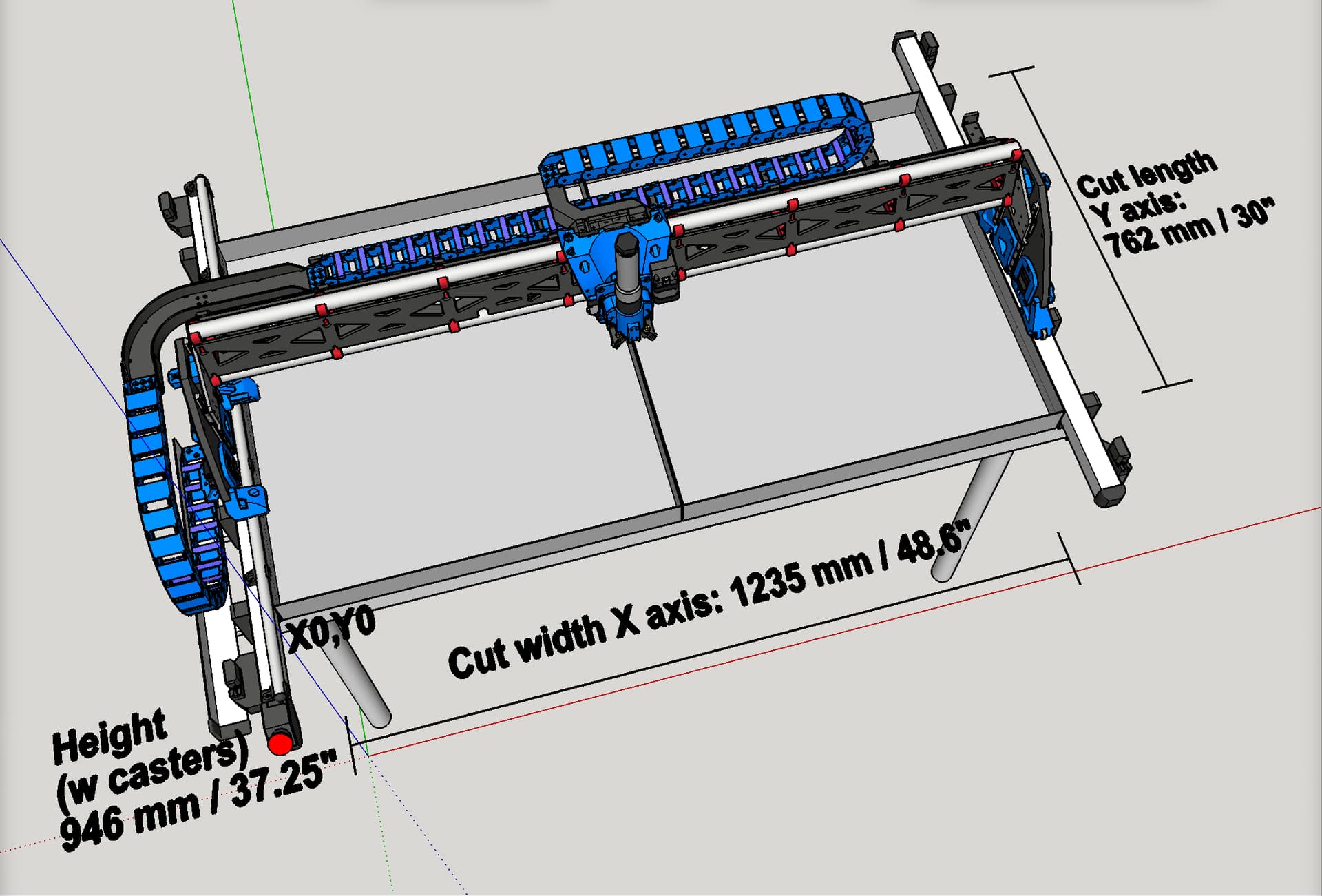
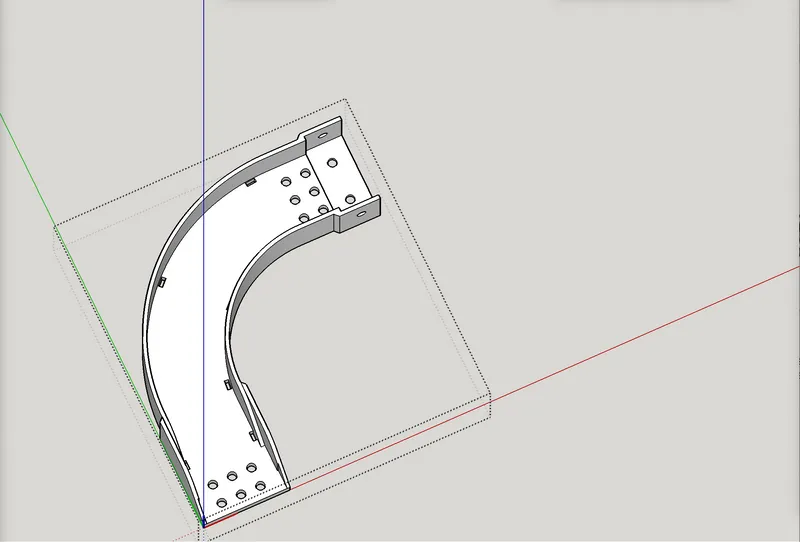
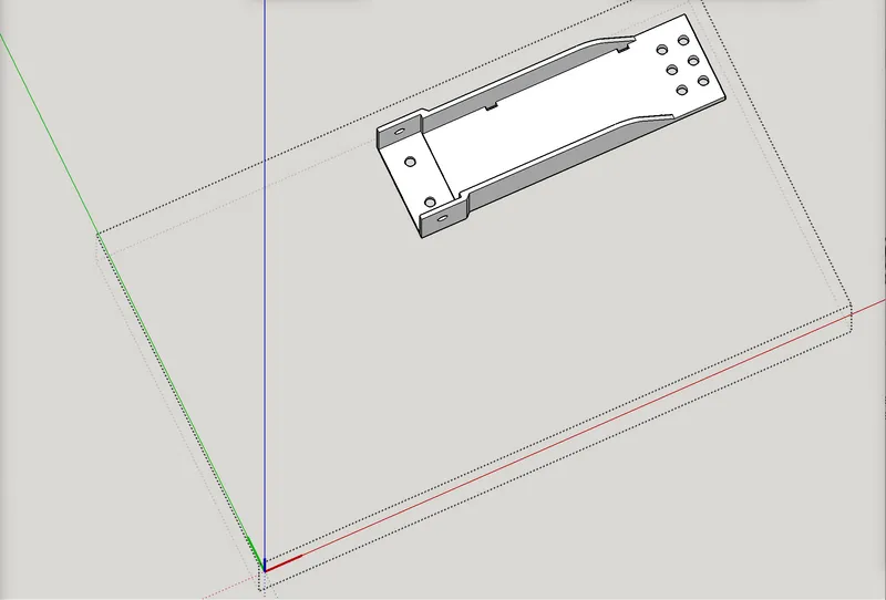
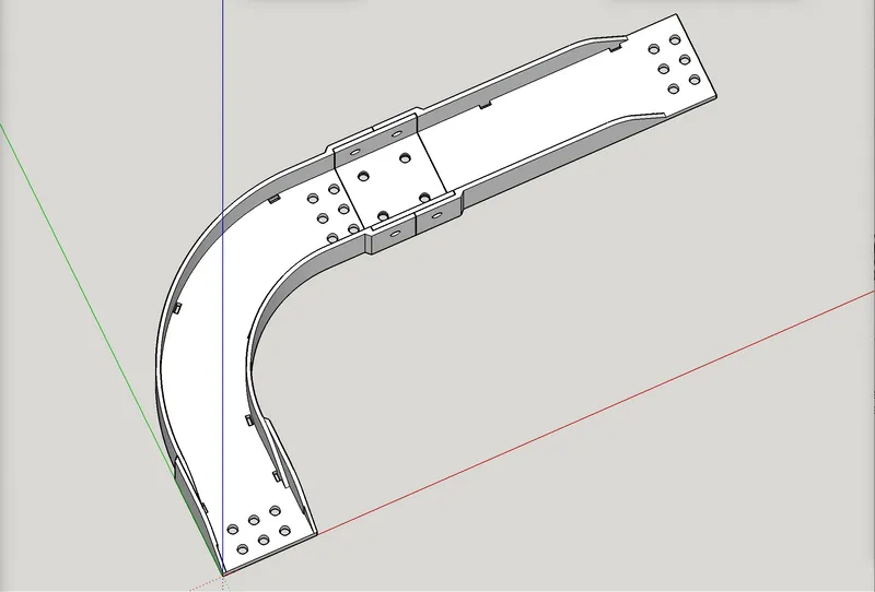
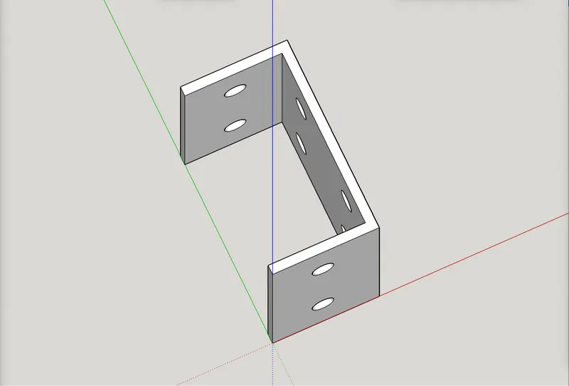
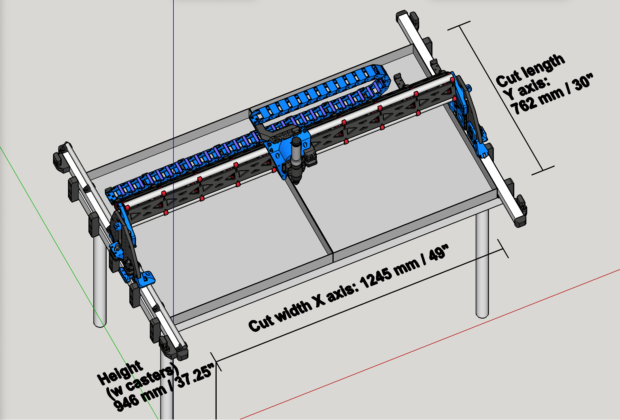
I designed these printed parts to attach 1.5-in aluminum square tubes to a VEVOR name brand stainless steel table, which became the base for my LowRider 3-based plasma cutting rig, which is documented both on the V1E forum and on my YouTube channel, and for which other printed parts are available here for free.
The table linked below is the one I used for my plasma rig (although I switched its legs for longer ones from another VEVOR table I had, and those other legs had casters mounted on them). I paid $259.99 for the table, but as of March 2023 the price had increased to $302.99.
- Stainless steel table: https://www.vevor.com/stainless-steel-work-table-c_10625/vevor-stainless-steel-table-for-prep-work-60-x-30-kitchen-equipment-stand-p_010166423043
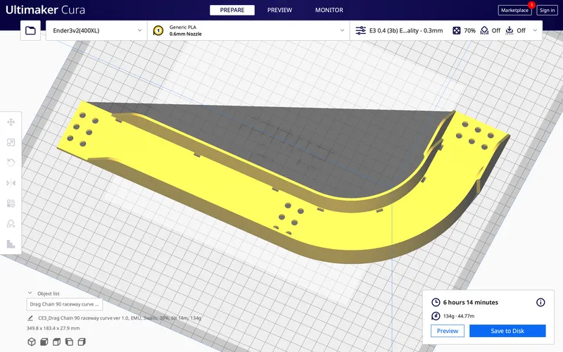
Print settings:
- Print as oriented.
- No supports needed.
- If printing with 0.6 nozzle, I suggest 2-3 walls, 30% infill.
- If printing with 0.4 nozzle, I suggest 3-4 walls, 30% infill.
Mounting tips:
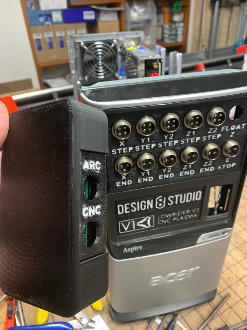
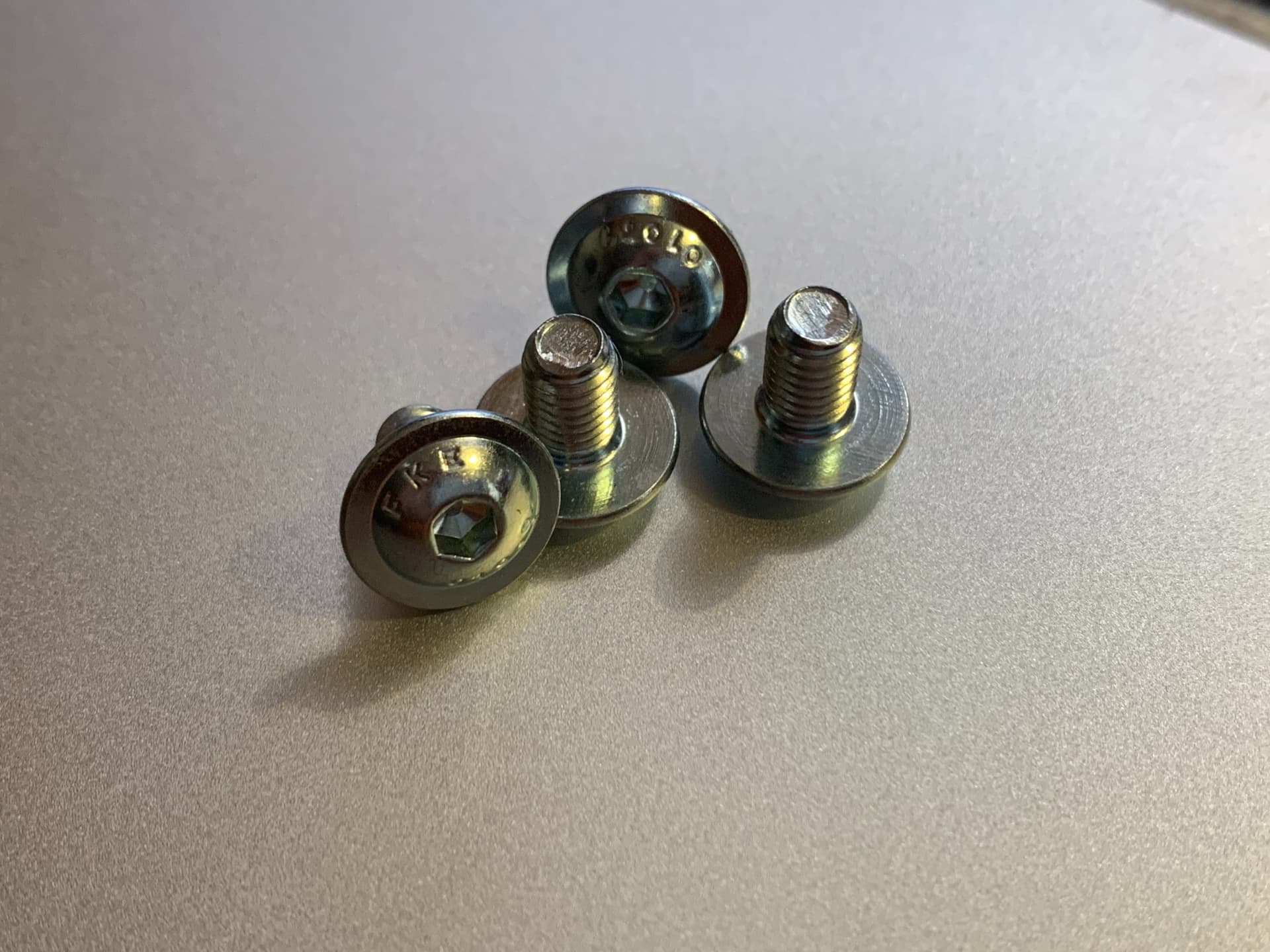
- I used M5 x 8mm screws (as shown in the photo) to attach these to the table. There is an existing screw hole on the VEVOR stainless steel table (each hole has a compression nut in it) that I used. I seriously considered drilling an additional hole for each mount, but in the end I did not. So, although the mount has three screw holes, I only used two, one for the table (on the lower end) and one for the aluminum square tube (on the upper end).
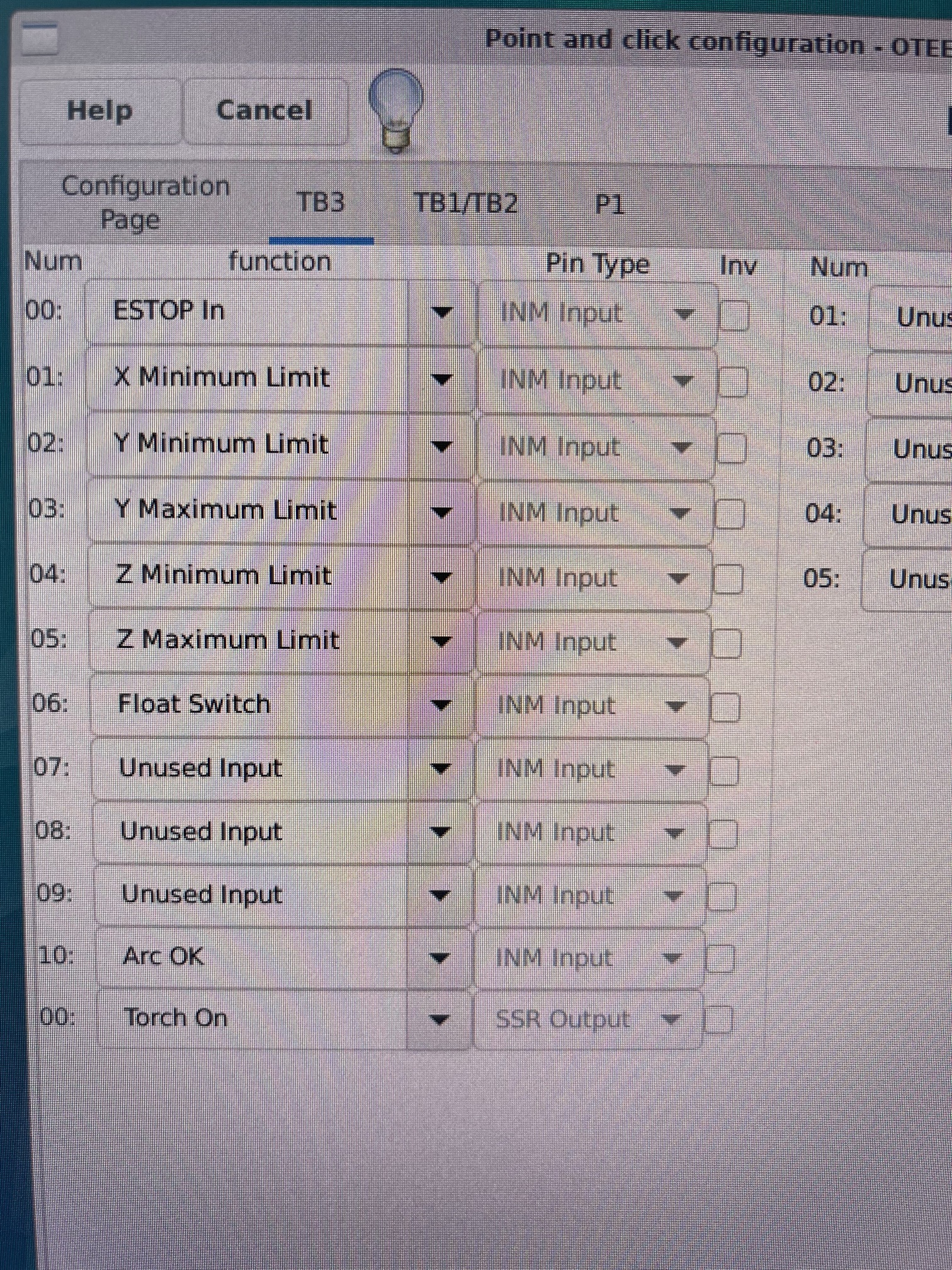
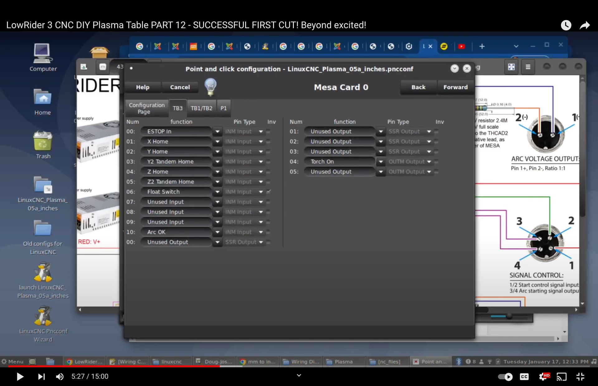
Various links of interest related to my plasma cutting build, based on LowRider v3 and LinuxCNC:
- Wiring schematic: LowRider 3 - Plasma Build "On a Budget" - Clarksburg, WV - #68 by DougJoseph - Your Builds - V1E.com Forum
- V1 Engineering - LowRider v3 — LowRider CNC V4 - V1 Engineering Documentation
- My LR3 CNC Plasma build thread on V1E forum — LowRider 3 - Plasma Build "On a Budget" - Clarksburg, WV - Your Builds - V1E.com Forum
- Printable files of my torch mount: LowRider 3 CNC Plasma Torch Mount with floating Z and magnetic breakaway, prints without supports (v1.2) by Doug Joseph (design8studio) | Download free STL model | Printables.com
- Printables.com COLLECTION of parts for LowRider 3 CNC PLASMA Table: CNC Plasma Cutter Collection by Doug Joseph (design8studio) | Printables.com
- The first six (6) videos of the video series are part of a playlist devoted to the torch mount. The playlist is available here: https://www.youtube.com/watch?v=MV-IcyFUPQs&list=PLiW6LQZxE6JaOT7bpK6Z6k35rYtBaWuFp
Amazon affiliate links to plasma cutter, machine torch for it, and consumables for each:
- CUT60DN Plasma Cutter: Amazon.com
- Consumables for CUT60DN: Amazon.com
- PTM80 Machine Torch for CUT60DN: Amazon.com
- Consumables for PTM80: Amazon.com
Amazon affiliate links to project related items:
- TB6600 Stepper Motor Driver 4A 9-42V (3 pcs set): Amazon.com (I got 2 sets, for 6 total. 5 are needed for LR3 plasma rig)
- 24V Fans: Amazon.com
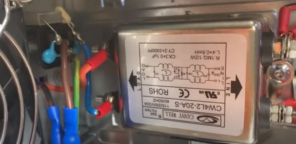
- EMI Filter: Amazon.com
- 5V Power Supply (5A, 25W): Amazon.com
- 24V Power Supply (15A, 360W): Amazon.com
- Fast-Blow Fuse Kit w Inline Fuse Holders (175 pcs): Amazon.com
- 13A Fast Blow Fuses (10 pcs): Amazon.com
- Machine Power Switch: Amazon.com
- DIN Rails (20 Pieces): Amazon.com
- E-Stop Emergency Button Switch + 6 pcs Endstops for CNC: Amazon.com
- Aviation Style Quick Connectors Kit (2 Pin / 3 Pin / 4 Pin / 5 Pin): Amazon.com
- #1 CGELE 6 Sets Terminal Blocks, 4/5/6 Positions 600V 25A: Amazon.com
- #2 CGELE 6 Sets Terminal Blocks, 8/10/12 Positions 600V 15A: Amazon.com
- Butane Soldering Station Multi-Function Self-Igniting Torch Kit: Amazon.com
- Zippo Butane Fuel (for the Soldering Torch): Amazon.com
- Solder Wire 60/40 with Flux Rosin Core: Amazon.com
- Heat Gun 1800W: Amazon.com
- Mixed Quick Disconnect Solderless Crimp Terminals 540 pcs: Amazon.com
- Ferrule Crimping Tool Wire Pliers w/ Wire Ferrules 1800 pcs: Amazon.com
- 18AWG 6pin wire: RGBSIGHT 10m 18 Gauge RGBCCT LED Strip Extension Cable 18AWG 6pin 6 Color Stand Electrical Wire for RGB+CCT RGBWW LED Ribbon Lamp Tape Lighting 33ft Wire Line: Amazon.com: Tools & Home Improvement
- Metric Taps Set, 6 pcs, M3 M4 M5 M6 M8 M10, Titanium Coated HSS: Amazon.com
- ¼" Air Compressor Filter Regulator Combo (for back of plasma): Amazon.com
Amazon affiliate links to products used as shown in Torch Mount portion of the video series:
- MGN12H Linear Rail Bearing Sliding Block Match use with MGN12 Linear Guide for CNC xyz DIY Engraving Machine (200mm, H-Type) — Usongshine MGN12H Linear Rail Bearing Sliding Block Match use with MGN12 Linear Guide for CNC xyz DIY Engraving Machine (200mm, H-Type): Amazon.com: Industrial & Scientific
- End-stop I used for floating Z — from a set of 6 high-quality end-stop switches that came included with an Emergency Stop button I ordered from Amazon — Push Button Switch AC 400V Red Sign E-Stop Emergency Mushroom 22mm NO NC + 6pcs End Stop Limited Micro Switch for CNC — Push Button Switch AC 400V Red Sign E-Stop Emergency Mushroom 22mm NO NC + 6pcs End Stop Limited Micro Switch for CNC: Amazon.com: Industrial & Scientific
- Crimp-on spades used to attach wiring to end-stop were from this set — Nilight 540PCS Mixed Quick Disconnect Electrical Insulated Butt Bullet Spade Fork Ring Solderless Crimp Terminals 22-16/16-14/12-10 Gauge Electrical Wire Connectors Assortment Kit, 2 Years Warranty — Amazon.com
- Evolution Power Tools R185CCS 7-1/4" TCT Multi-Material Cutting Circular Saw, 7-1/4" — Amazon.com
- Female Thread Brass Knurled Threaded Inserts — Amazon.com
- M2 M3 M4 M5 Alloy Steel Socket Head Cap Screws Nuts Set 1060pcs Carbon Steel Screws Assortment Kit — Amazon.com
- Round Magnets (12mm x 3mm) — quite good — eventually shown in use in videos #5 and #6. Quite strong, and working well for this use — MIN CI 100Pcs Super Strong Neodymium Disc Magnets, 12 x 3mm Small Magnets for Dry Erase Board Whiteboard Office Fridge Crafts, Mini Round Rare Earth Magnets for DIY Building Scientific Models — Amazon.com
Amazon affiliate links to some other items for LowRider 3 CNC:
- Hex Head Allen Wrench Drill Bit Set, 20 Pieces: Amazon.com
If you have any questions, I’m on the V1E forum as Doug Joseph (design8studio) or you can ask here via the comments.
My PayPal tip jar: https://paypal.me/design8studio
Various LowRider 3 CNC remixes:
View all my models and remixes on Printables:
*Amazon product links are affiliate links.