LowRider 3 — Aza's IDEX upgrade (2 Routers!)

I bet there is a ton of footage coming that is getting run through some custom software…

Parts > Print Core > Attempt #1

Done bunch of small-medium prints on my MP3DP v4, have printed test cubes, large rectangles and temp towers to calibrate. Even so, I probably should’ve tuned more before kicking off this print, but what the heck… This’ll be the first yuge print on my MP3DP, added custom Fan Duct for the occasion.

No idea whether these are good/bad settings. Initial layers are laid. We’ll see what happens…

Edit: Changes while printing (layer ~26 of ~550) :

  • Dialed back speed to 80% after noticing 100mm/s infill was causing printer to shake too much and result in blobby mess. Doesn’t help that I forgot to take printer off a low profile lazy susan before printing :man_facepalming:
  • Dialed back extrusion to 97% after noticing nozzle seemed to be too low and carving through material previously laid. Vaguely recall calibration test cube wall thickness was a few percent too thick, so this makes sense.
2 Likes

You did a max flow rate test? 120mm/s with what diameter nozzle?

I think I max out at 55mm/s with a 0.5.

In terms of settings, I usually do the infill the fastest/or 120 width and a touch slower on the outer walls.

2 Likes

That’s a really good idea, so no, I forgot/skipped that. Did kind of test max extrusion speed when calibrating steps by feeding 100mm.

After checking dimension/skew accuracy I skipped a few tests, and jumped straight to the “suck it and see” test… 0.6mm noz, 0.32mm layers. Reduce speed a few layers in down to walls ~64mm/s, infill ~80mm/s, while rocking on a lazy Susan, vibration dampened with microfiber rags.

Everything’s going great, no problems…

Part cooling duct too high?

Edit: Done. ~9hrs 47mins. Hopefully dimensions are ok…

4 Likes

This test really opened my eyes. CNC kitchen has a blob test that you weigh…I want to try that one. Teaching techs is more quick and dirty, run it until your extruder skips or doesn’t flow smooth, then back off a bit. That got me to right where E3D said it should be (even though that info does seem to be sort of buried). I have not tried the H2 yet.

3 Likes

Parts > Print Core > Attempt #1 FAILED - Too tall

Checked Print dimensions (relative to the print bed’s XYZ orientation). XY are great, but Z height is ~5mm too tall :man_facepalming:.

Problem:

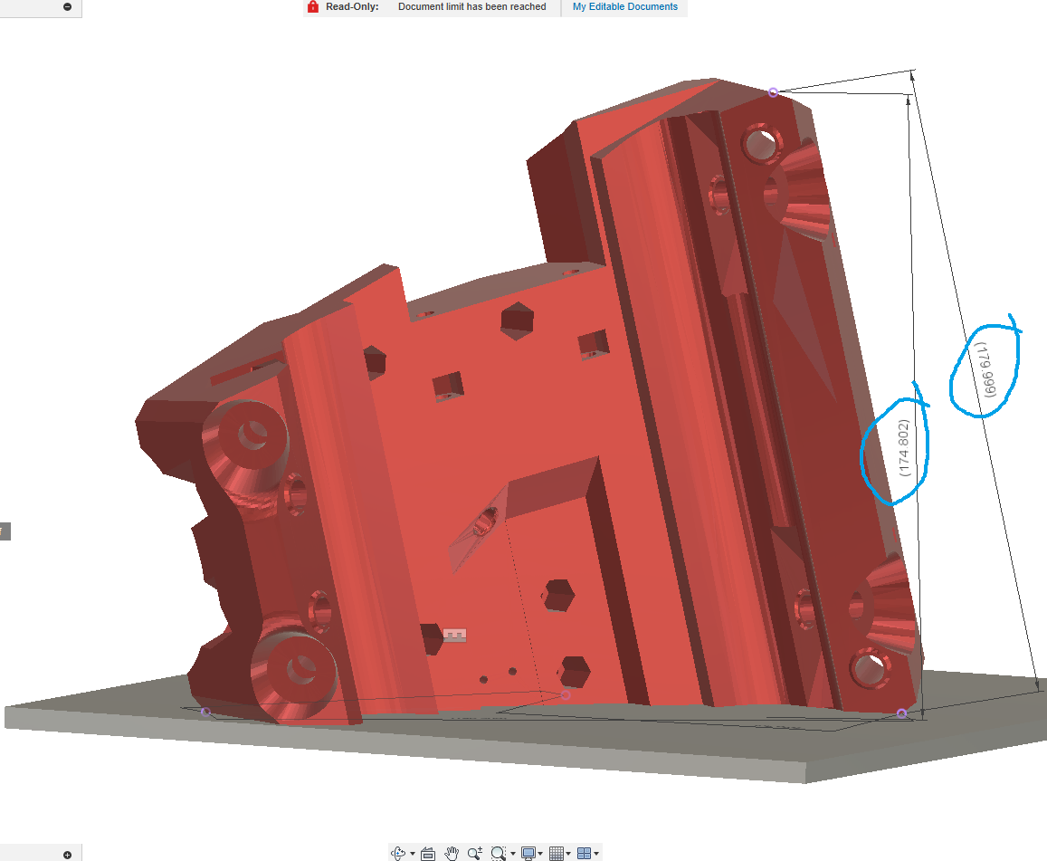
  • Print Bed to highest point is expected to be 175mm (see dimensions in Fusion 360 sketch below). But my print actually measures 180mm.
  • Core width is expected to be 180mm. My print actually measures ~184.5mm across.

Cause/Fix:
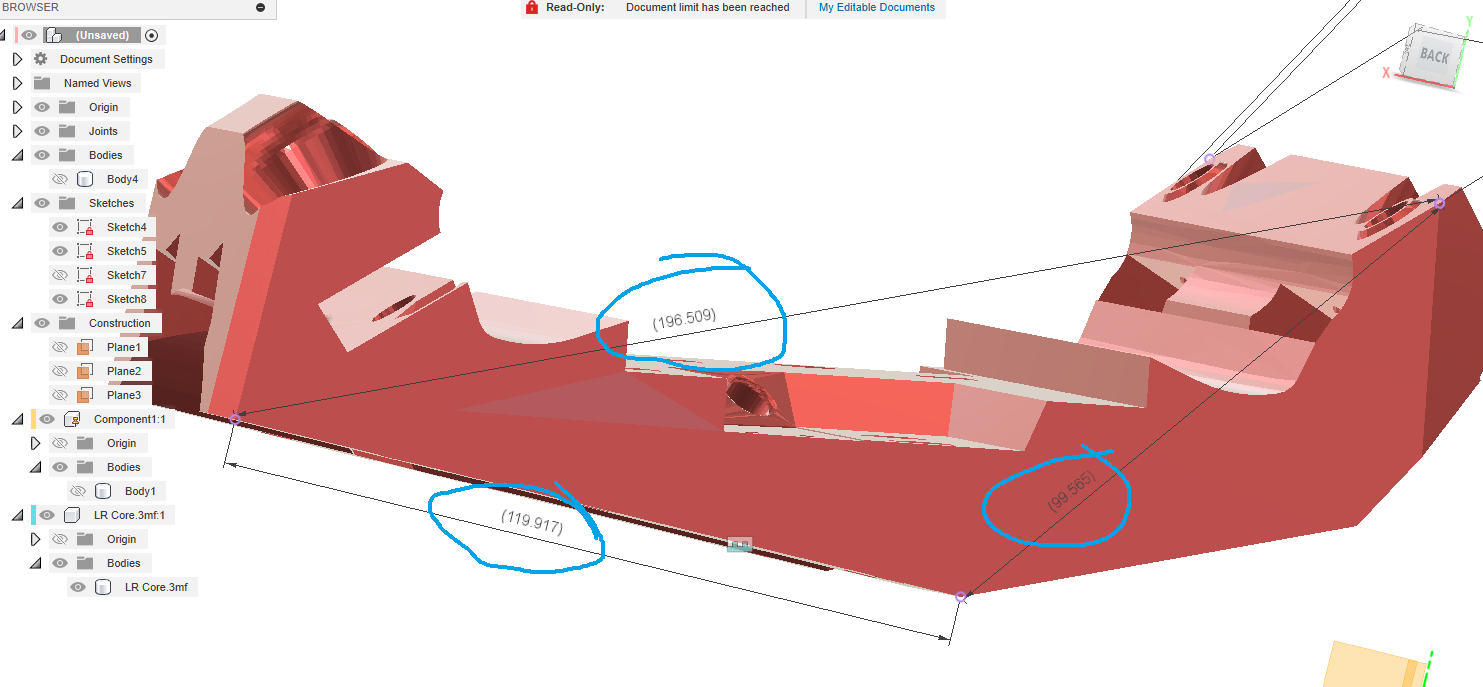
Didn’t calibrate Z axis as well as I thought. For my penance, have spent time measuring edges/diagonals of significant features touching the print bed :

Tempted to add calibration marks, slice and print first 2mm to verify dimensions/skew. Will use to compare against my existing LR3 Core. Reason being the existing Core was printed ~yr ago on different printer, I should verify new calibrated Core will match before doing another full print. I potentially might end up intentionally mis-dimensioning the new Core to match the old one.

Will recalibrate Z then kicking off Attempt #2

What your steps are off a tiny bit? That doesn’t seem right. Should be a whole number.

1 Like

Well, it could be out a bit on an MP3DP with belted Z… I have had pretty good luck with my belts personally.

1 Like

Parts > Print Core > Attempt #2 Success

Completely my fault, I calibrated Z using a pathetically small 20mm cube. The irony is that after calibrating again my Z rotation/esteps are back to 32. Related Klipper config edits.

Checked Z height this time by homing XYZ, Z-tilting, then moving Z axis to largest distance possible that could still be accurately measured from the bed. Ended up using the Attempt #1 Core and some other objects as measuring sticks…

2mm thin core slice from new printer matches 1yr old Core from diff printer close enough. Kicked off Attempt #2

Update: Attempt #2 in-progress. Consider Stick On Temp Gauge on Steppers mounted to PLA. Back when I first saw Stick On Temp Gauges, I laughed and thought they were a bit gimmicky. Today’s different, while observing a long running print, the stickers gave me useful information to not overly enclose and smother the printer. The nice and quieter snuggly towel wrapped printer quickly started to heat up with steppers getting to a point that would be an issue for PLA mounts. So, although am using PETG, have unwrapped and left the front open until if/when am using higher temp materials (ASA?).

Update: Attempt #2 done. Looks great. More importantly, dimensions and layer adhesion are great.

5 Likes

Now you have a core for destructive testing…

2 Likes

Put a router in it and tighten the mount as tight as you can. Bet it splits in half LOL

Plan / Design > Router Power and Control

Short: Bought NOYITO 4-Channel Relay Module, 5V trigger, Optocoupler Isolation, Load DC 30V AC 250V 30A to control power to Routers (and maybe other stuff) via Controller board’s Fan pins.

Long:
Enabling gcode to control power to each Router individually would be nice. @srcnet shared link to Enclosed High-Power Power Relay for Arduino, Raspberry Pi, PIC or WiFi, Relay Shield, looks neat, I hadn’t looked at before. Dug around the forum and found several folks seem to like and recommend this solution for easy and relatively safely controlling power to Mains powered devices. Dug around for product info:

Until now, have been turning Router on and off manually, guessing most people do, it’s easy. Originally had lofty goals of adding a relay, and PID speed control. But as usual, got distracted and ended up prioritizing other stuff… Despite this track record, instead of doing the quick safe option mentioned above, am going to try a 4-channel 5V triggered 30A rated Relay Module hooked up to my Octopus’s Fan ports. 4-channels instead of just 2, because might end-up achieving lofty goals of hooking up Vac, cooling, lights, lasers, etc… Have to make an enclosure at this point, so may as well include space for futures.

  • Was considering SSR, but they seem too reliable and pricey for things that needs relatively infrequent on/off switching?
  • Saw AMZN’s best selling HiLetgo OptoCoupler Relay Module is rated at 10A, which was too close to the Router’s 7A for me.

Related

6 Likes

In general, “Horizontal Scaling” designs are great, but this…

Parts > Unboxing

@vicious1, thank you kindly for the “IDEX Kit #1” bag and other goodies, including the JackPot collectors edition pcb, nice! :slight_smile:

5 Likes

That’s awesome!

Looking forward to watching your modification.

2 Likes

I am eagerly waiting for you to tell me this works so I can do it.

1 Like

Boom, Outdoor IDEX build! Your turn, start building…

4 Likes

Looks like I need to get off my butt and finish enabling Marlin on Jackpot. Once the 2209 serial multiplexing is sorted, it’s all solved and IDEX will work, guaranteed.

On FluidNC it is theoretically possible.

1 Like

Am sticking with Marlin on Octopus for this LR3 upgrade to IDEX. Looking forward to using Jackpot for future project…

3 Likes

Assembly > Core > Fast (un)Mount potential?

Err, am I the last person to realize the LR3 Core can be mounted and unmounted without having to remove XZ plate from Gantry’s end brace? Can just add/remove two of the top bearings.

https://youtu.be/fK0YfAu1jGg

Longer term, thinking about belt length adjusting quick’sh release X belt holder mod, and/or right leadscrew stub mod…

3 Likes