Louisiana LR3 build - Orange/Black/Blue

So, I went out and upgraded my FluidNC to 3.7.8 and then said I was done for the night……but then thought, let me just check the square real quick so I have a starting point for tomorrow.

I tried to be meticulous when I placed my belt mounts, but I couldn’t get it exact, so I was expecting it to not be perfect….

But I have to say, I feel really good about my first squareness test.

Here’s what I did:

Homed all axes
+50 Y
+30 X
Lower V bit to mark
Then I made a rectangle
+1200X
Mark
+1500Y
Mark
-1200X
Mark
-1500Y
Mark

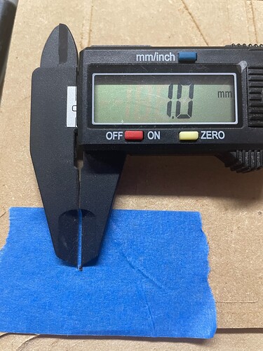
That last mark?? 1mm to the left of starting mark

Then I measured the diagonals.

1/16” or ~1.58mm out of square on a 1200mmx1500mm rectangle(or 47.2”x59” for those of us that are metrically challenged)

I’ll chase it some tomorrow, but was pleasantly surprised at how close it was on the first test

1 Like

That is troubling. The marks should always hit the same spot every time. They just are not always in a perfect square, but should always be in the exact same place. You should even be able to power down home, and hit each mark again, perfectly (they might just not be in a perfect square until you dial in the digital offsets).

Just to add to that…your pen mount needs to have extremely light pressure, High pressure will absolutely move the mark.

I like to use a vbit and pop a tiny hole in the blue tape top mark my spot. Pretty easy to automate with a few lines of gcode.

It was the v bit, I just dotted it with a marker after so I could see it easier

I agree it’s not great that it wasn’t exact, but I haven’t gone back and adjusted the belts and stuff yet after messing with the strut plates and all that, so I’m glad it was at least close. The Y was dead on. The X was off 1mm.

I’m going to check it again tomorrow. I was driving it manually on the “Tablet” tab, so I can’t guarantee I didn’t accidentally hit something when I was trying to park it. I’ll maybe write a little gcode file so the movements can be all at once instead of relying on me pressing certain buttons all in the right order

2 Likes

And now that I’m thinking about it…

I cut 3 56.25" strut plates yesterday, and that difference didn’t show in those. They were cut in 4 passes and there was no offset after making the rectangle 4 times.

So I’m guessing something just needs to be readjusted after installing the plates today, or must have hit a button at the end. The almost exact 1mm now has me suspicious…

2 Likes

Ok, now for some learnings I had towards the end here…

Spoil board

While planning my table I didn’t really put a whole bunch of thought into the spoil board, I just planned to throw some MDF up top, which is what I ended up doing.

I ended having to remove it because I just cut it to my table length rather than sizing it to my addressable cut area, which is important if you plan on surfacing it.

Strut plates/Braces

Installing the strut plates was a bit of pain for me. I can certainly see how having captured nut slots would have made it way better. I talked myself out of printing Doug’s remix of the braces after reading a few opinions that they aren’t necessarily better because they can spin, etc.

I think if I had to do it all over again, I might print the version with all captured nuts, and glue/epoxy them inside the slots ahead of time so they are even less likely to spin. Installing the screws into them doesn’t take a large amount of torque to snug up the strut plate, so it feels like that would have been enough to make it hold, and made assembly much easier.

That being said, it really isn’t the worse thing in the world as long as you are using Ryan’s open strut plates, as you can bend your fingers around through the holes to hold the nuts in place, then use a long, skinny wrench to grab the nut.

I can’t imagine trying to install them without captured nut slots and 3 solid strut plates.

It’s also easiest to install the back strut plate last as you can insert the nuts into the slots ahead of time on those as long as you are careful not to push them out accidentally.

Brace count

My build size called for right at 8 braces. I don’t really know if it makes it much stronger, but I decided to go with 9 braces so the spacing was a bit less than right at 200mm.

I later figured out that if you have an odd number of braces, you don’t get the fancy cross in the middle of the strut plates, so I added an extra brace. Now with 10 braces, they are only spaced 157mm apart.

What I didn’t consider, though, is now I didn’t have enough screws in the hardware kit to be able to install screws in every hole. If you are in the US, it is not easy to source matching hardware from a box store. I wiped out all the supply nearby to get 10 screws. There were also no M5 locknuts to be found, either. So if you are going to over spec, be sure to account for extra hardware.

Strut plate

There was a conversation recently about whether or not the keyholes were necessary on the strut plates and it was decided they were a nicety, but not really required.

I decided to go ahead and keep them so I could just pre-install all the screws and slip it into place without having to detach the hangers and stuff I already had riding on them. Well, I’m glad I checked after one screw was placed, because the keyholes are too small for the head of the M5 screws that came in my LowRider hardware kit in the shop.

So beware of this.

Strut plate design

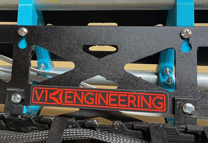
I did like the little V1 logo cutout @vicious1 has on his strut plate in the center

, but I opened the parametric Fusion 360 file and changing the width to a larger build doesn’t place the logo correctly.
image

I found this out too late to spend the time fixing it for myself, as I was at the point already that I was ready to cut them. This is also missing from the OpenSCAD version.

Anyway, a little long-winded, but these were all the things going through my mind yesterday while trying to get all 60 screws in place :slight_smile:

3 Likes

I’m considering a remix made for adding threaded knurled heated inserts (aka “heat-serts”) in place of nut capture slots. They have more grip, are less likely to spin out.

2 Likes

Good feedback! Will hopefully help someone at that stage in their build.

I’ve not tried those before in PLA. I have melted some PLA using the nuts themselves to better form some slightly undersized capture slots, but it was in some random holding cases that didn’t need any kind of real rigidity.

Having never done it before, I would be concerned I would mess it up and leave the nut misaligned from the hole or something. Edit: I guess you could put the screw through and use it to pull the nut in and keep it aligned that way?

Maybe something I will test and play with in the future. Could be a good path forward.

1 Like

One can get straight alignment by threading a screw into an insert, and if the screw+insert shows as crooked, holding the soldering iron on the top “corner” where the screw meets the insert, and using pliers to nudge it all into alignment. The screw can be removed once all is cool and hard again.

They really only require super precise alignment when a very long approach, through a thick material, is happening. In this case, there would be a decent amount of forgiveness.

They are not that hard to align visually when inserting them.

1 Like

I honestly have no idea what happened last night, but I went out there again. Belts seemed ok, but I tightened them up a little anyway.

First test seemed to repeat last nights result, but I was unsure again as sometimes the Tablet page lags a bit and I end up double tapping things.

So I reset everything again and ran through the following motions

100x100 square
500x500 square
1000x1000 square
1200x1500 rectangle

In each of the 4 tests where I was making sure to be careful of what I pressed, the v-bit laid right back into the same hole.

That hole position remained the same through all 4 tests and didn’t deviate at all

1 Like

That is what I want to hear!!! Nice. You can measure the diagonals and use M666 to make any small tweaks you might need to get them perfect.

This will do for now :slightly_smiling_face:

3 Likes

Heck yeah!

1 Like

Making my way through my list….

4 Likes

Ok, finally getting around to a follow-up on my experience cutting those plates last night.

I made 2 mistakes…part of the learning process I guess.

First mistake:

I didn’t realize my router was sitting too high in the mount. So about 5 holes in I realized that the last 3-4mm of cut depth the core was riding on the workpiece and wobbling around.

So I had to stop, readjust router depth, and move down my board and try again.

Second mistake

After the first cut went ok, I went inside for a bit, then back out to the garage.

Started my job, it marked my 12 holes, and tool change time.

So I grab my tools, change the bit, power back on the router, and press Resume. Crap! Forgot about the probe. So I had to rush and turn off the router and grab the probe. In my rush, I accidentally knocked the probe and touch plate together as I fumbled to retrieve them.

So there I was…with my Z 20mm above the workpiece contemplating what to do…and I did the wrong thing.

What I should have done:

Stop the job. Return machine to X0 Y0, Run the job again. This would have let me verify that the first tool hit the exact same holes again as it should, and I would know it would be alright. I thought about this being the correct way to do it 4 seconds after it was too late…

What I actually did:

Thought to myself: Oh, well I think this tool change looks like it must have come back to 0,0, so I stopped the job and started over. Then my V bit was off and didn’t hit my original hole.

I found out that the tool change code actually moves to X0, Y10 shortly after I had already started the new job… so I had to stop and move down my board, and start over again.

I’ll likely change my tool change code to go to 0,0 instead of 0,10 just in case I need to stop and start over again in the future like that.

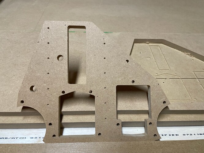
In the end though, I finished the night with 2 usable YZ plates, which is what I was after.

Follow-up

Tool change

After a very short time marking those small holes on the YZ plate, the bit and router is already extremely hot. What are you guys using to do your tool changes? Is it just my router getting hot that quick? I measured it in the 120-140ºF range.

Probing

After Probe, the imported settings move the bit to Z10. This is a really tight spot to unclip the probe. It’s probably fine if you are just using the magnet, but I think I’ll raise mine to Z20 for a little extra space

Makita Router

As I said, my router gets extremely hot. Like I’m concerned I’m risking deforming my PLA. I ran a surfacing job the other night and made the mistake of running it between 1 and 2 on the speed dial towards the end. Makita says don’t do that :slight_smile: . The cooling fan doesn’t move fast enough at low speeds, so afterwards I measured the temps north of 150ºF.

LR Core

I think my core has a little bit too much play in it. Some of my bottom bearings seem too loose and it feels like the core can move too easily, as I saw when it bottomed out. I’ve seen a few posts about tightening and squaring the router, but I still don’t quite have a handle on what I need to do, like a clear picture of exactly what happens when I tighten/loosen each those nuts.

Some of the cuts showed a little bit of slop in them because of this, as you can probably see in the picture.

FluidNC

It would be nice if those messages telling you to probe and whatever had some kind of popup. Some times I sit for a bit before I realize it stopped for me to do something since I don’t have my router controllable by the gcode yet, so I don’t have the power off to prompt me.

I also saw in the Discord that there is a Probing tab, but it is missing from my interface. I also see someone mention Tablet Mode vs Regular mode…anyone know what that is??

Alright…rambling over for now…we’ll see what I “learn” tomorrow :slight_smile:

3 Likes

I was looking and I had some thermal pictures of my routers. I can’t find it. They do get hot, 140 sounds really high though.

I usually run mine at 1-2 all the time. The heat is why I do not make this giant monolithic clamps that people keep making (those are fine in aluminum,. My small clamps have not failed yet but 150 sounds pretty high.

Hmmm. For the core that bottom bolt tightens those two bearings. So right bottom bearing tightens the right top bearing. I think the biggest issue is how little you need to tighten them to get a good balance.

There is a check box to enable it, just not sure how useful it is. I do it in gcode exactly where I want it to be.

The best part of tablet mode is the gcode visualizer, other than that I do not use it.

I guess it didn’t click to me at the time, but I guess they just meant the “Tablet” tab. I use it all the time to manually jog because my finger too easily hits the wrong length on the main screen.

I did finally get to go back and tighten it up yesterday. I just tightened them both in roughly 1/8-1/4 turn increments until both bearings made contact with the rail and had roughly the same amount of resistance on it, but was still fairly easy to turn by hand.

I haven’t run a cut again yet, but I intend to go back through the squaring process again to check it all again this weekend.

Seems very high to me, and I don’t have anything attached to the router except the 2 small mount clips right now. I might need to exchange it or something just in case.

If you have not run it much the temps do go down from what I remember. A few of us tested a new router and initially I complained about super high temps, it didn’t take too long for them to come down. I think the brushes need to wear in or something. I lost my email thread so I don’t have the exact data.

Well……that was fun while it lasted….

Haven’t messed with the machine for a few days. Went to the shop to go ahead and square it up.

Powered it up.

Home Z. Fine.

Home Y. Grinding noise…

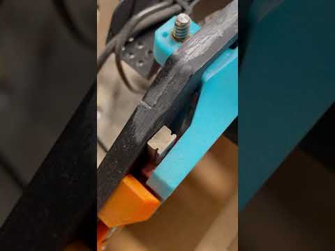
Not sure what happened, but the printed YZ plate almost looks warped. It definitely moves easy in and out, and the linear rails seem like the screws aren’t holding good anymore.

So I guess those MDF ones won’t be sitting on a shelf after all…

1 Like