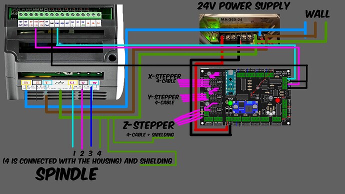
I am out of ideas. @Ryan @jeffeb3 @jamiek any of you all stars?? Wood works aluminum does not.
i will make u a picture now to hope to understand my setup ![]() Maybe u see instant whats wrong
Maybe u see instant whats wrong
Unfortunately, some of those spindles are terribly electrically noisy.
If grounding the workpiece makes it worse you have a big problem. I would start with testing things with a multimeter to see if you can track down stray voltages. From the ground pin to anything you can safely probe.
You need to clean up the board wiring, having wires cross over each other and all the components is not a good idea, and any wires related to the spindle need to be completely separate. They should not be bundled with other wires (ideally cross other wires at 90 degrees). Some spindles are really nasty. Getting shielded spindle wires and grounding the shielding at one end is also best practice.
My only question is are the grounds run direct to a common point, or are they daisy chained? I can’t tell from your pictures. That could cause a ground loop which can cause weird issues. I’ve seen issues where guys have daisy chained grounds between a bunch of vfd’s. Just my two cents.
Good Point.
On 2 Points the PE is really chained.
Im gonna try that
I think the first thing to do is either add ferrite rings or some sort of cable shielding to your wiring to eliminate RF. I had issues with a stepper motor acting up on my 3d printer, the stepper would act like it was hitting an object before it got to the limit switch. The issue was RF interference and adding ferrite cores resolved the issue in my case.
@Mattk331,@vicious1,@Russ all have great points. I have had to troubleshoot many flakey problems like this.
Think of the alumimum plate as a antenna, the Vfd and spindle as RF generators. The power supply is also generating high frequency. Every wire and cable can be part of a current loop.
Most likely some of this is getting back to your controller board.
Things you can do:
Make sure that the power leads to the VFD do not have loops or are parallel to the wires of the power supply or leads to control board. If possible keep the power cables as short as possible
The ferrite beads on the input to the control board are a good idea.
When using shielded cables only ground one end of cable. Make only one ground point for all cables.
You might also put a .001mf cap across the input of the power supply to your control board.
Last thing to keep in mind. Earth ground and Power supply ground are not the same thing. Try to only have one point common if you find it needed. I am very rusty on EU rules.
I orderd a arduino uno with cnc shield now.
So i can change the Controller and the Power supply.
New Update:
i changed the Power Supply.
I took the Frequenzy Converter of the Tillboard. At the Moment the Spindle ist started and stopped by Hand.
My test is a rectangle 50x50
1 Layer in 0,5mm and after that
1 Layer with 0,1mm, starting at 0,5mm
After the first run i repeat instantly without touching the Settings.
When in the 2. Run, the Spindle is at 0,5 i hear nothing.
When its at 0,6mm i can bearly hear and see that some Material is getting off.
Let it be 0,05mm or Less. For a CNC out of a 3D Printer, im fine with that.
BUT When i connect the Frequenzy Converter to the Tillboard, the Error comes back.
I ordered ferrit cores to see if that helps.
But im very close ![]()
Very good troubleshooting. You might consider putting the CNC controller in a shielded box with Ferrite on the input power leads
Is that the Vevor one?
Yes its this one for 1,5kw.
My Friends, its done ![]()
After changin the Power Supply, to split the Controller and Frequenzy Converter to its own Power Lines. And putting a Ferrit Cores around the Cables from the Controller and the Spindle.
My MPCNC is not going down in Aluminium anymore. ![]()
I still have a Problem that my CNC and the Plate is not perfect leveled to another but that is not a electrical Problem.
