Hello-
I’m wondering if someone can check my work on hooking up a laser to my MPCNC (before I actually hook it up). I’ve been digging through information all morning and come across quite a bit of conflicting/old info (stuff about hooking it up to D9, etc.) but I think I have everything figured out now. I’d just like someone to verify this is correct before I do anything further.
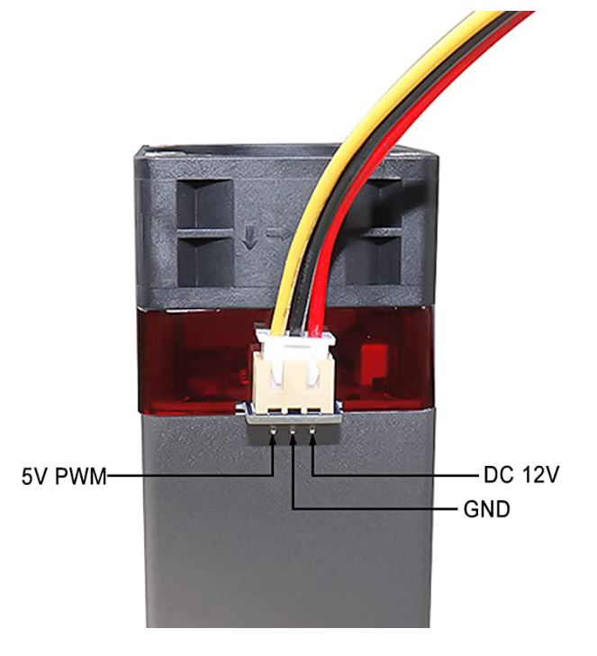
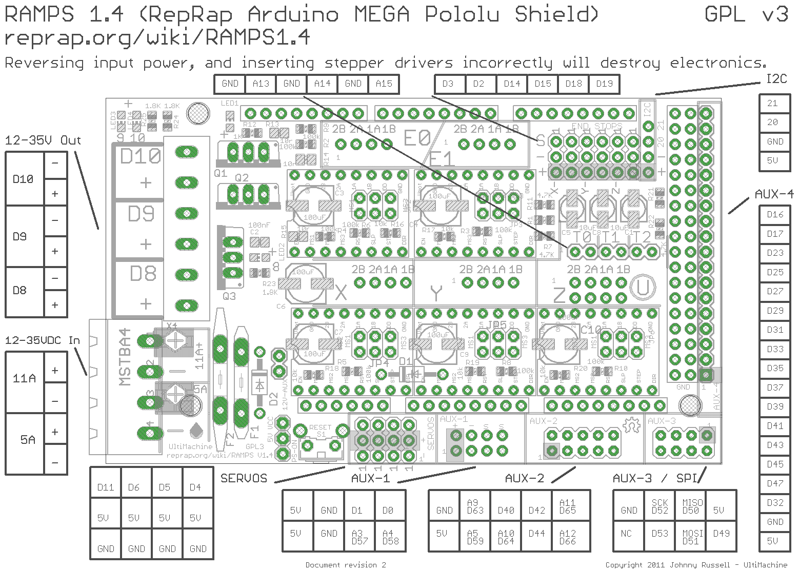
I have a 12V laser module with a 3 pin hookup (12V +/- and 5V PWM) and am running a RAMPS 1.4 board using the 515 dual endstop firmware.
From what I understand I should plug the red lead right into the 12V input on the RAMPS board, the yellow PWM lead into pin 44 of AUX-2 on the RAMPS board, and the black lead to ground. I’ve seen info that some use the ground on the green 12V plug, and others use the ground at the top left of AUX-2. Does it matter which one is used or is one preferred over the other (I’m clearly not an electrical engineer  )?
)?
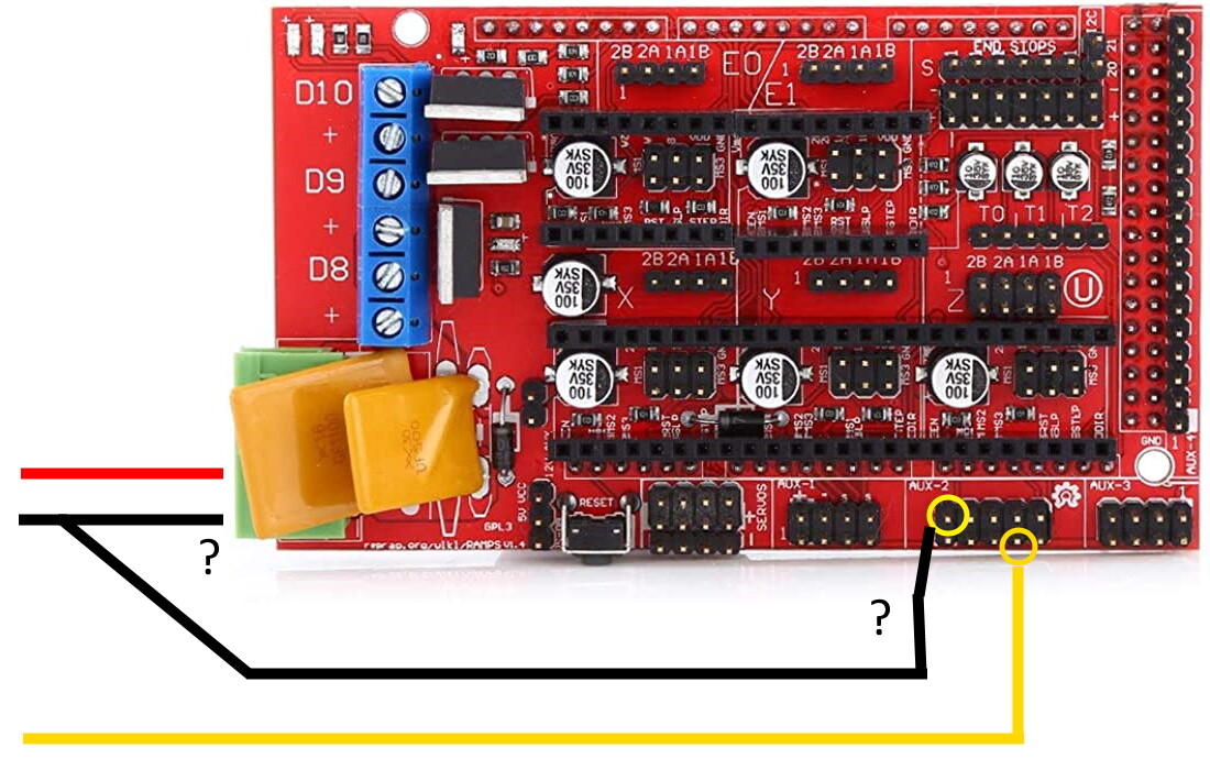
Other than the ground question, does everything else look correct?
It sounds like the 515 firmware has the laser enabled, so nothing further to do on the firmware end, correct?
Thank you!