As for running the cnc and laser together, I haven’t. I’ll have to try that, I’ve been working on the laser burn power settings currently, but to do that I think you will have to essentially do a tool change, like you do between different bits when just using the router. The tool Z height’s (cutting depth vs the focus Z) would be different in my mind.
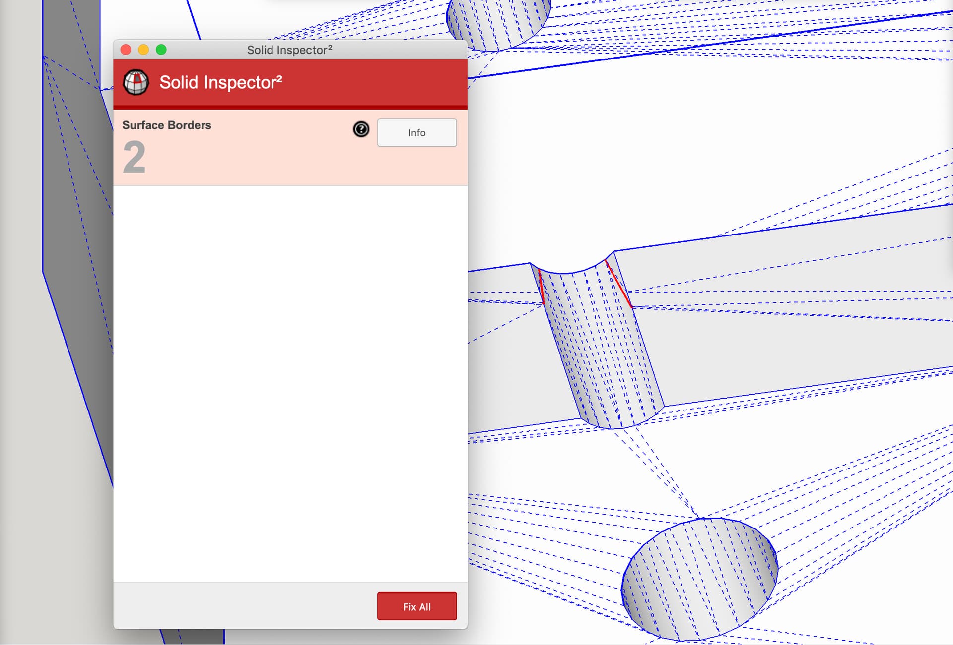
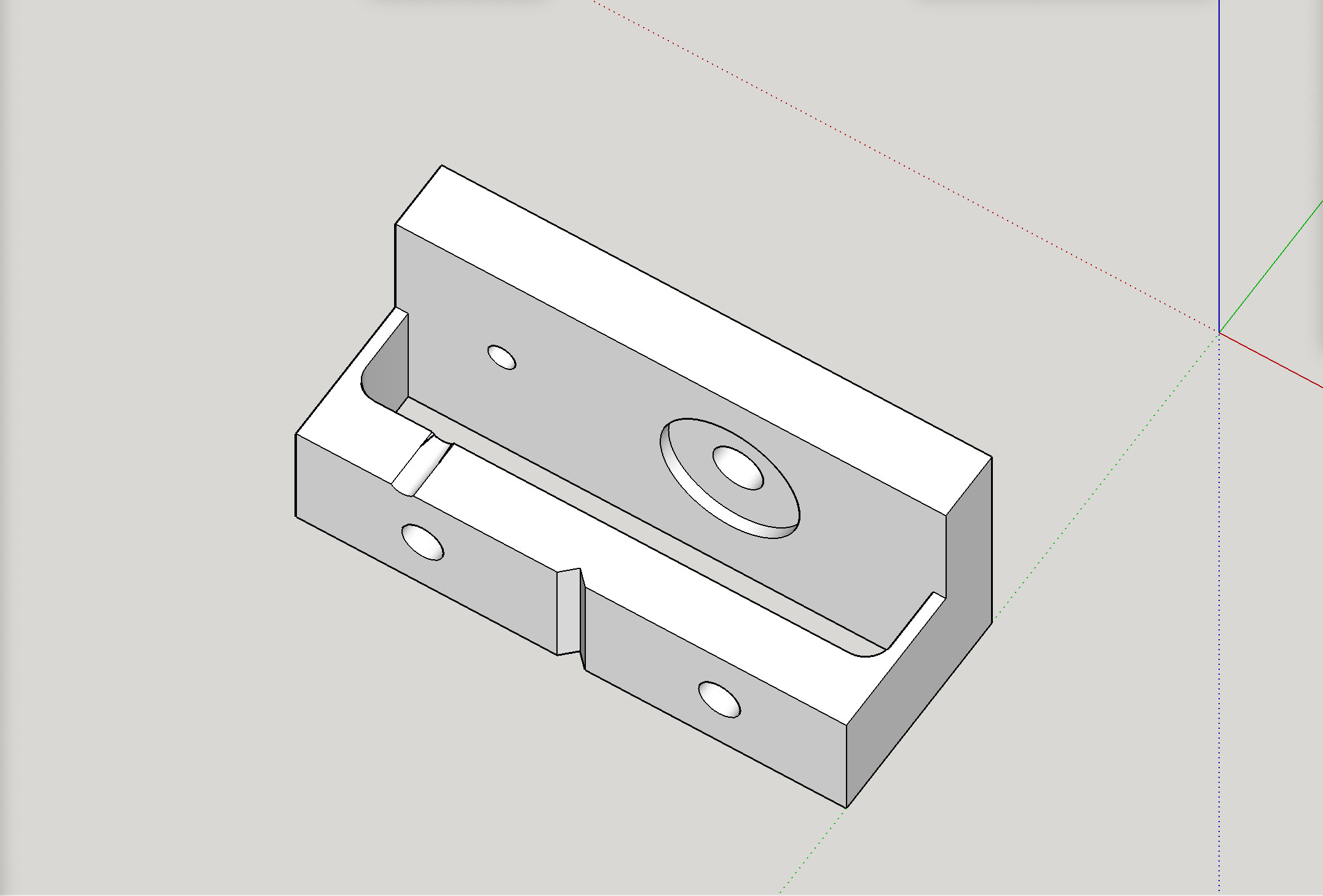
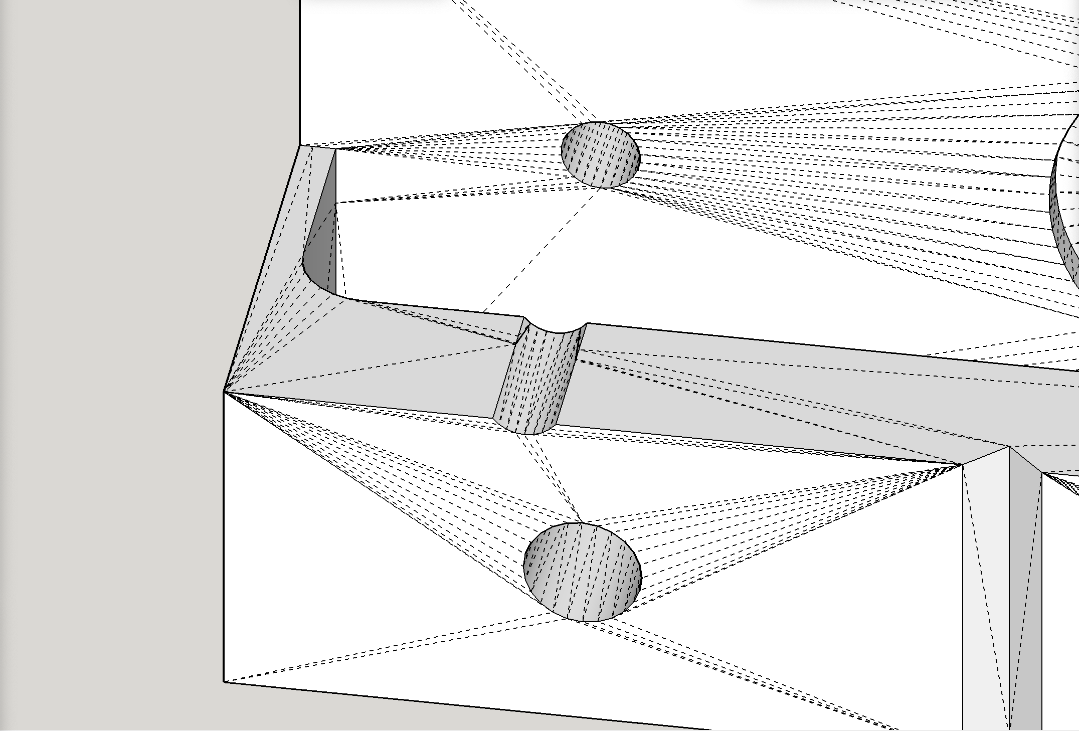
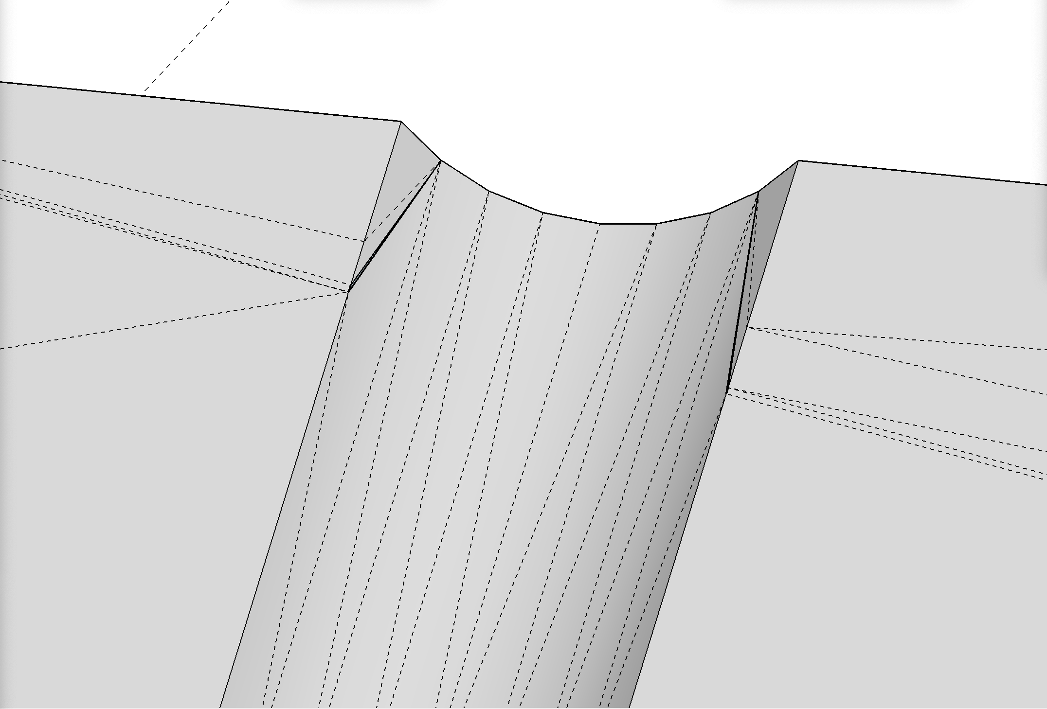
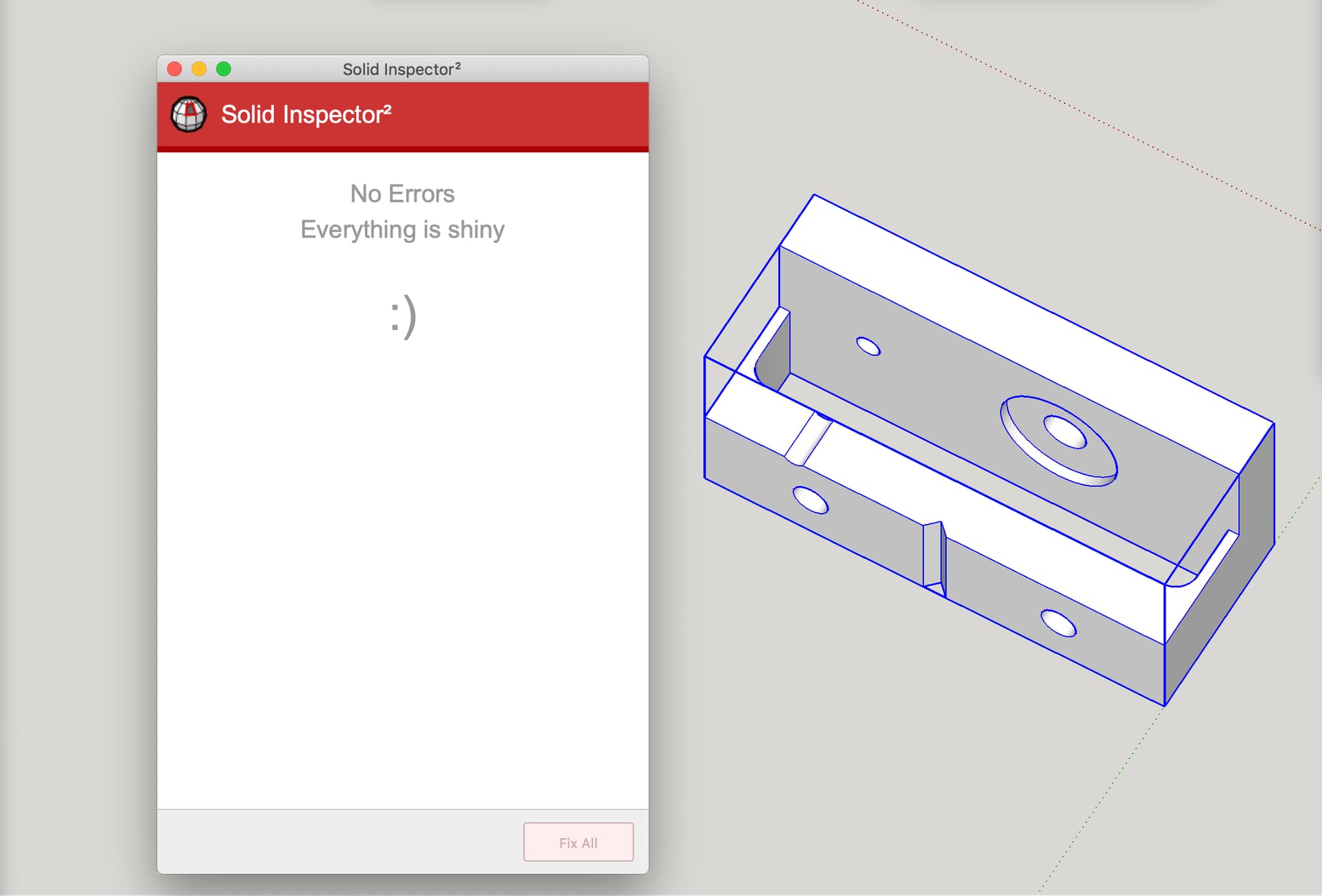
I noticed that Printables does not show a 3D model of your STL in the 3D viewer, so I downloaded the STL and checked it out. It has two holes in it, which means Printables declines to show a model in the viewer, since it’s not “watertight.”
The holes are small enough that the model is probably quite printable, since many slicers can forgive tiny holes and slice the job anyway.
However, it’s always good to run a “solid inspector” type test and fix holes.
If you upload this attached version to your Printables page, replacing the earlier one, I think you’ll see them grant you a model view in the 3D viewer.
Yes it does, I just used the 1mm spring file and left the part A alone. I am hopeful they do use the same aluminum bracket and the tolerances are there. I had to print 2 because of my hole expansion setting from a previous print setup in cura.
I printed out a new part A and your mount. Need to expand the holes a little since I can’t put my bigger bolt through as is, but that will be ok
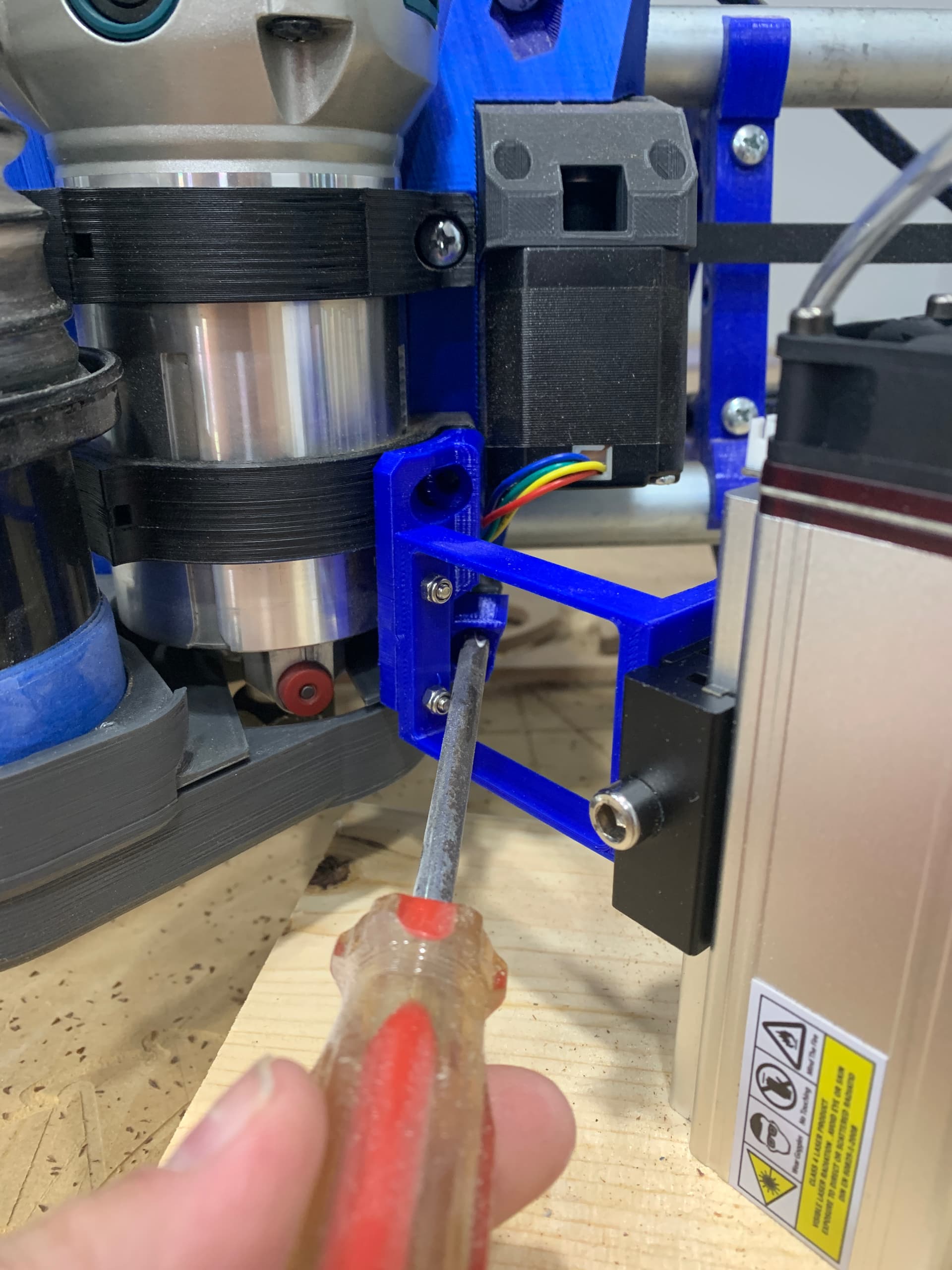
It’s late, I’m tired so I’m sure I’m not seeing it. But I’m stuck with how to install it. First I assembled the two pieces, and resided I couldn’t mount the aluminum plate. So I disassembled
Attached plate to part ‘B’, attached that to part A- and now I don’t have clearance for the large m5 bolt to mount it over the dust shoe mount
So I need to attach A to gantry, pre-assemble B plus mount plate- but now I see I won’t be able to attach A to B without first removing the router in order to get access to the small bolts. Even then, it’s a tight fit since I’ll be screwing them in from inside the tool holder which is a small space for my tools
Here are two possible approaches that could allow assembling the new Part B after Part A is installed:
Either “heatsert” some threaded inserts into the Part A (might require either drilling out a bit, or remixing a bit), or glue some nuts into back side (hidden side) of Part A (also might require some remixing).
Another approach is to remix Part A with some capture slots, but instead of gluing in nuts, instead insert bolts, with their heads in the capture slots. Then, either nuts or wing-nuts could be tightened onto the front side to attach new Part B after Part A is already installed.
UPDATE: So, I started to post a Mount A part that had capture slots on the back intended for M3 hex head screws (instead of nuts), but when I went looking on Amazon for M3 hex head screws, I found they are apparently like unicorns and 4 leaf clover.
So… maybe just use the normal Mount A, but epoxy the screw heads into the back, and install Mount A before installing Mount B. Then, when you go to install Mount B, the screws will hopefully stay in place well enough to get nuts tightened on (or wing nuts if there is room).
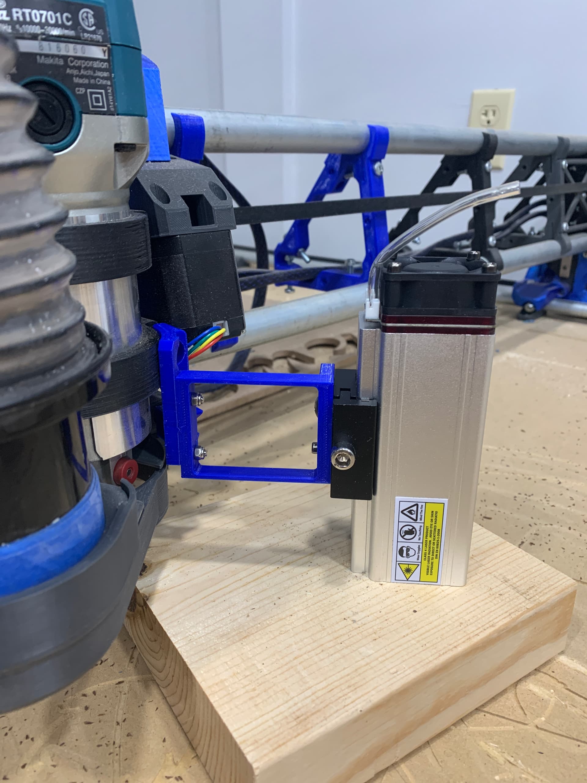
@Neilp if you want to try it, I remixed it again (Laser moun V3) for a test but haven’t had a chance to print. I added 1mm to the spring sides for strength, extended the surface the aluminum plate mounts on, out 38mm, and moved the aluminum plate screw holes for better access.
From a quick measure on my machine, it looks like 38mm would be just far enough to access the M5 bolt on the LR core, but like I said I havent had a chance to print a trial run, hopefully soon. I apologize for the previous issues, this is just me doing trial and error lol.
Sorry bud, I was just taking the 25mm as a great suggestion lol
Laser works great, I can share what info I’ve gained if you need. So far basic engraving is easy, but I’ve been diving into engraving photos we’ve taken but there’s a lot of trial and error messing with the contrast and dpi. I highly suggest running the trial with Lightburn, I’ve had great luck