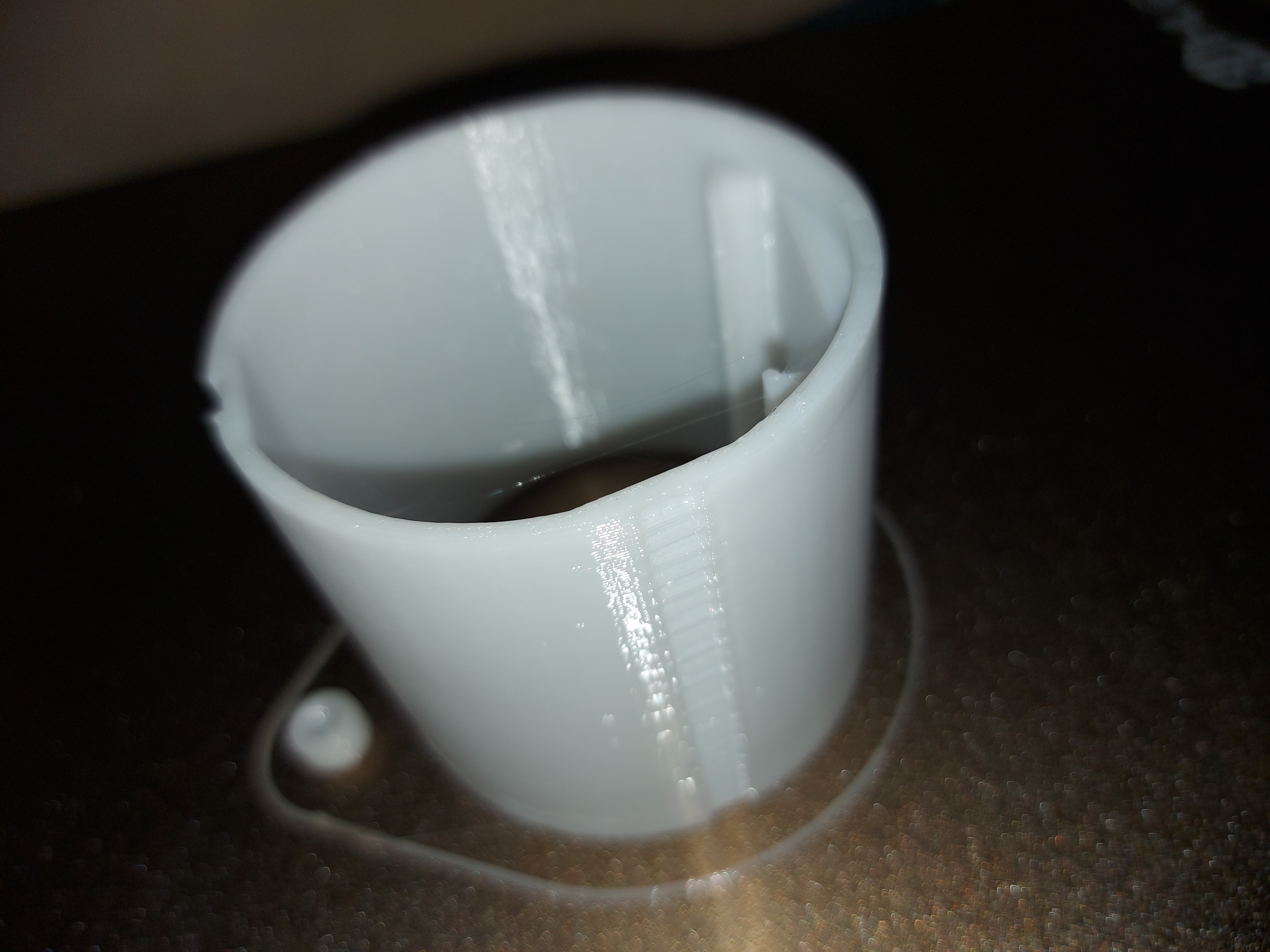
Here is a modified version for the LowRider with a slot for the protrusion and gear teeth. I don’t have the Makita base, so I followed Dan’s Pen mount closely including shape and spacing of the gear teeth and depth of the slots. Thanks @ SupraGuy. I tried to place the slots so the additional mount thickness would not interfere with the laser or the air assist. I also removed the raindrop ventilation since it doesn’t make sense inside of the Makita mount and probably increases print time. If I was working on this for myself, I’d probably print out the first 10mm or 15mm and test it before printing the whole thing.
Edit: It just occurred to me that for the Mikita base, the height might be significantly taller than is required. If so, let me know, and I’ll provide a shorter model. There is no reason to waste the material or the print time. The current height is driven by the spacing of the two halves of the Primo mount.
If the model is the “right way up” then the slot and the gear teeth are in the respective wrong positions. As viewed from the top, the slot is 90° clockwise from the geared teeth. (I can see how you might have mistaken this, since that pen mount prints upside down.)
Thanks for the catch. I’ll fix it this evening. One question I had was the shape of the teeth. If I bisect the teeth, the top half has a different angle than the bottom half. That doesn’t make sense to me, but I don’t know much about gears.
Yeah, I did that because the lower angle was too sharp to print well, and I was getting sag into the hole. The slightly steeper angle on the top printed better and still worked well for the gear teeth. I could probably have used the same angle top and bottom, but the space between teeth was also kind of tight.
I’m using a online print service, so the advice to do a test piece isn’t a possibility. Let’s just hope this is going to work!
The knob that controls the gear teeth is on the top of the base, so I guess the full height is the best solution.
The previous version, of the laser mount I printed, was a little bit to wide and needed some sanding with a belt sander. I measured my router and the size is 64.8mm. I see your model is 65.0mm. Is it possible to make it a little bit smaller? If that’s to much trouble I will print is as it is and do the sanding.
Here is a version that is 64.7mm. I reduced the outer diameter but kept the inner diameter the same, so the walls will be just a bit thinner. I didn’t want to reduce the inner diameter due to how close the corners of the laser are to the walls.
My original model was 65mm. It fits fine into the Primo Makita mount Ryan modeled, though the layer lines made it a bit rough installing and removing. I ended up hand sanding it for 5 minutes so insertion and removal would be smooth, but nothing aggressive like a belt sander, and I’d be concerned about melting rather than abrading using a belt sander on PLA.
I wonder if a AMB 800 FME spindle could feet in that same cylinder…
I also have Neje 40640 and i am looking for an universal tool mount that doesn’t require to unscrew anything when a tool change is needed.
EDIT: I’ve just checked trying to fit my 800 FME in a 65mm Makita base and it doesn’t fit
None yet as I just received the spindle for (late) Christmas.
I was thinking to use this one : PrusaPrinters
I’m happy because it’s a good spindle, but i wouldn’t have choosen that spindle by myself because i think the 43mm attachment ring is a limitation in term of versatiliy but my brother really likes Kress/AMB and i could not ask him to return it for other brand.
I will have to deal with not that easy tool changing.
I hate that as I already ruined 1 of the 2 nut hole of a nut trap trying to remove the upper tool mount and beeing able to remove /destroy completely the nut trap inside the tube was a real pain.
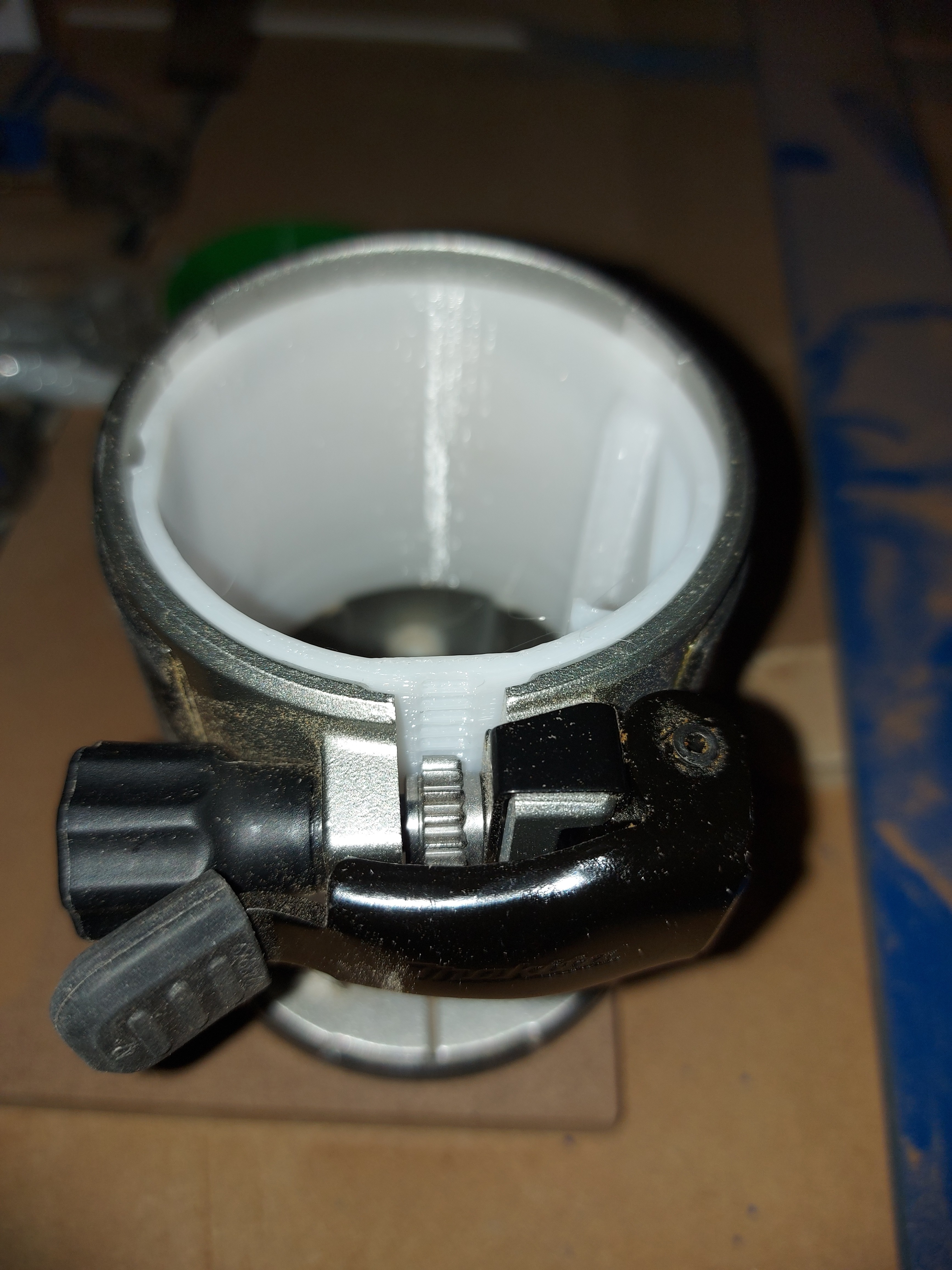
Fits in easily, and when clamped, it is held in place firmly.
I’d have given you bonus points if the set screw had been either 1/4" drive or used an Ikea Allen key wrench, either of which I have in abundance, lol. I might remix it a little, but I can verify that the 65mm model fits in the original Makita mount perfectly.
Eventually, I’ll have the NEJE laser module to put in it. I already have a 5.5W so I’ll hold out for an A40640 to get that 10W cutting, which will make a nice combo with the LR2
I received the 64.7mm version from the 3dprinting store, and it fits perfectly, I didn’t even had to sand it, it is a snug fit. Strange that there is a small different between the same routers.
The laser hangs a little bit below the mount. The laser mount is all the way in the makita base but there is still a couple of centimeters between the bottom of the laser mount and the underside of the makita base / lowrider base plate. That’s why I push the laser mount as for as possible down in the makita base and after that I push the laser also as far as possible down until it won’t go further because it hits the makita base. That way the laser sits stable in the makita base and low enough to have the focus length between the material.
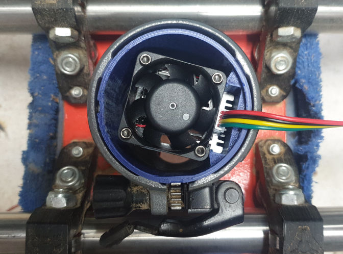
I printed this too for my Low Rider and it holds the laser very well (thanks for the tip on the print height).
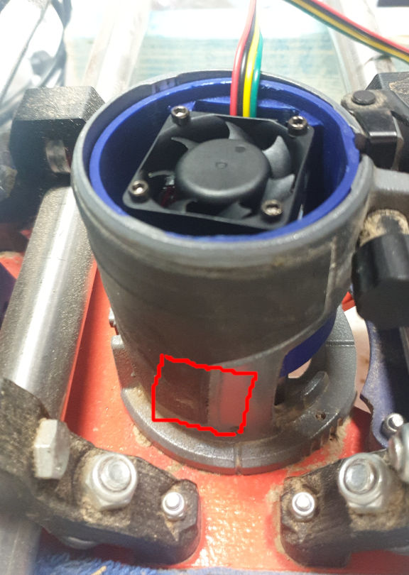
The only problem with it, is the orientation of the laser. At the moment there’s about an 8mm gap to squeeze an air hose down but if the unit was rotated about 100 degrees, it would face forward. Then you can use an air assist that attaches horizontally.
Window facing to the left.
.
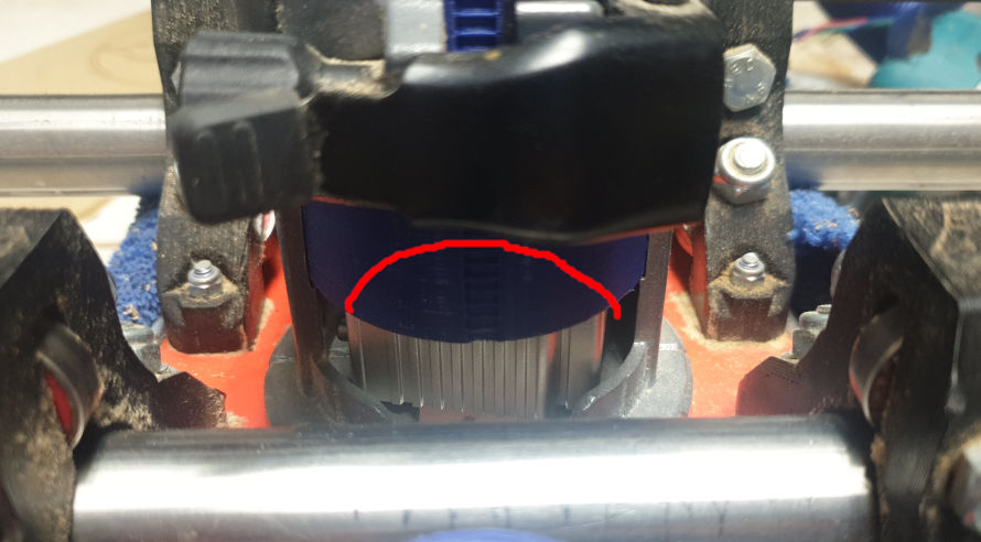
Rotate laser and cut this section out for access/viewing.
.
My laser bottoms out on the router mount. Add 6mm for the thickness of the base plate… it’s about 14mm from the laser to the bottom of the base plate. That gives me 8mm clearance - ie: 22mm focal height - to the top of the work piece. Not a lot to play with, but doable.

 because it’s a good spindle, but i wouldn’t have choosen that spindle by myself because i think the 43mm attachment ring is a limitation in term of versatiliy but my brother really likes Kress/AMB and i could not ask him to return it for other brand.