I really don’t know where to add my congratulations on a job very well done! So here they are.
Do you think If I cut off one of the pins on the plug it’d only get half the voltage through a 220V socket? ![]()
I really don’t know where to add my congratulations on a job very well done! So here they are.
Do you think If I cut off one of the pins on the plug it’d only get half the voltage through a 220V socket? ![]()
I don’t think that’s how electricity works. Maybe try wiring two Kobalt Routers in series for your LR3 IDEX upgrade? Double check your home owners insurance policy first though.
Nah, Send it!
If you can get your hands on one (the Kobalt I mean) I think Amazon sells converters
Maybe if I only pushed the plug in half way? ![]()
![]()
If you are just using a circle that is offset by 1.5mm and only tangent at one point, I think I can handle that is you do not want to do it. What is the biggest thickness of the spacer?
Currently printing 2nd…
Noticed:
@vicious1, able to share .step files? No probs, if not.
It’s not a lot of steps. I think it took me maybe 30-45 min or so. I can do it tomorrow.
I think I spent more time adjusting the teeth and making the tool than anything else.
If I get all the way through it and don’t make any stupid mistakes like leaving sketches completely uneditable, I’ll put the whole the whole Fusion file up.
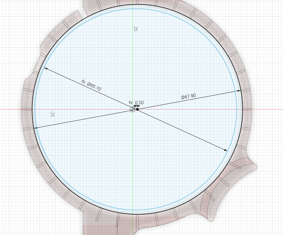
So, taking your original Makita design, I opened the hole up to to 68mm, but did it offset 1.5mm so it didn’t alter the thickness of the back side of the ring.
The Cam Ring on the inside had 0.1mm of clearance, and the sketch looks like this:
So the center of that circle was offset 0.5mm back(1.0mm from the original center), and then I just remove part of the back where the plastic was going to be thin.
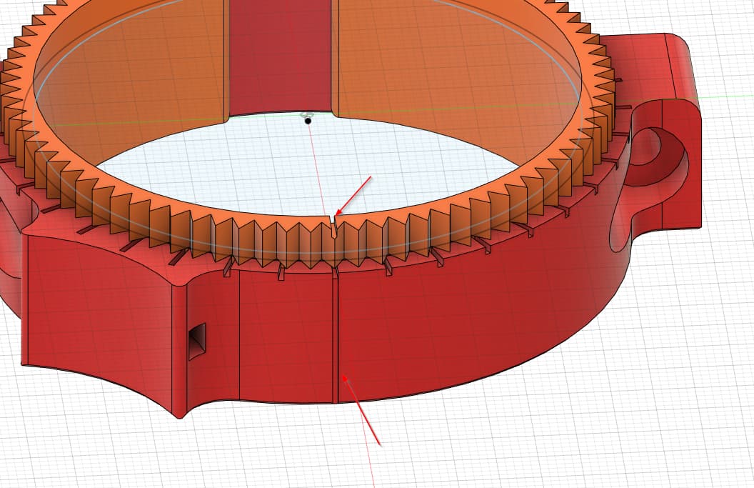
That’s all the easy part. The trickier part was setting up the notches on top and the front notch that aligned with the longer top notch that gave you the original alignment of the router with 0 adjustment.
One thing that certainly could have been better on mine with the Makita, was that since I didn’t have the original CAD, I couldn’t easily adjust to hose attachment, so I didn’t bother with it.
If you are going to make an official one, you’ll probably need to handle that better.
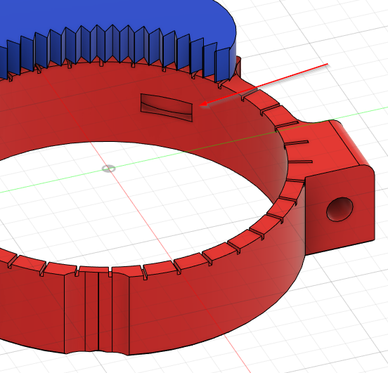
Another I did on mine was open up that back wiring notch a little wider. I was having trouble having mine get pinched, so I needed a little more clearance back there.
If you want to take a crack at it feel free. Just let me know if you have any issues or want some more information. I can still get to some of the sketches, a few of them are just not editable anymore.
Man I really need to get more into CAD. I know sketchup really well, just have never spend the time to learn F360 or FreeCAD
Nice, rule number 4 in the new giveaway gives me the opportunity to not participate twice. ![]()
It’s a nice thought, but it would only be to be one of the “cool kids” - the Makita is perfect for all I need, and I already own it.
A Kobalt would end up costing at least twice what the Makita did by the time freight and power adapter were added, and it would always be a compromise.
That doesn’t mean I can’t be a little excited for all of you, although I’ve heard that deWalt routers have plummeted in value on Craigs List lately - you might pick up a bargain there, and blue paint is cheap!! ![]()
That’s a really cool story.
But part of me feels like you may have left some NIL money on the table ![]()
Huzaa, I’ll get the PLA version printing right away.
Edit: PLA is started! It has about a Hour and a Half to print! I’ll come back with photos when I can! Welp the CAM ring lost bed adhesion and failed. The mount side turned out as expected all holes line up and everything. Re-printing the CAM now, this time with fresh glue put down.
As for the PETG if anyone knows why the sides on a hollow calibration cube would be a different thickness than the front and back would help speed up that process, assuming it’s a retraction/priming issue just not sure what to change to fix it. The the sides vs front/back are .1mm off (probably not insanely important, but never had that issue before)
That second hole would mess with airflow, heat, I think way more than the first one. So if you do open it up make sure not to use a funnel like I did with the first. I also did try a hole but it is too far away and still casts a shadow right at the bit. So I just skipped it, the funnel one lets light through that still lights up the bit.
Is the step file on the printable page, if not I can put it there.
The reusable zip ties I have are freaking huuuuge. There might be enough room? I can double-check, there isn’t much load so thin walls would be fine.
Scale it up larger would be my first guess. Tiny cubes only give very rough gross calibrations.
Thanks for the design insight and considerations. Can see .3mf but not .step ![]()
https://www.printables.com/model/628738-kobalt-router-lr3-mount/files
Its just weird to me its only with PETG. I’m giving it one more try before scaling, this time I changed a couple of retraction settings I don’t normally mess with and lowered the part cooling fan. It has been consistently 0.1mm difference between X and Y walls across all hollow cube prints.
In addition to what I mentioned above, consider also this helpful video for how to insert, and remove, collets from a collet nut:

Scaling to twice the size should only add a few minutes print time.
A tiny cube with that small of an error, my first guesses could be cooling imbalance or a crooked nozzle. If you scale up see if the error scales up or not.
I like the tip, although I’m thinking a smooth rod of Aluminum or Acrylic might be better esthetics wise. Maybe might even put a handle on it like a screwdriver.
Hmm, going to have to do some measuring. 3D print might even work, but metal or clear and shiny will look… well at least different.