Tiny tiny tiny
0603? or smaller?
I was reading the schematic backwards which is the source of my confusion. Yes, this will result in the input being 5V tolerant because it’s effectively presenting either 0V at low impedance or a high impedance that is then pulled to rail.
I’m back to thinking that this would work having the thermistor wired to ground but that what you’re measuring also has a diode drop in-line with it, which isn’t ideal. On the other hand, with the correct thermistor it also wouldn’t be a huge issue. The current through the diode will be low enough that the forward voltage should be relatively stable.
I still wouldn’t personally want to do it that way deliberately, but it’d work for testing or if you only need something coarse like over-temp. For bed or hot-end, I’d go with something more accurate.
The best way to protect input pins is to limit the input impedance. If you add the bypass diodes to GND/+V like in the schematic above, that means that the input signal will be clamped to +V and GND. The problem there is that a 5V signal from something like a power supply will drive a heap of current into the +V rail and pull it up to 5V, frying things. The easiest approach is adding some resistance inline to limit that current. If you’re only trying to protect to 5V, adding 1kR in series will mean that a 5V signal will conduct ~1.7mA into the rail. As long as everything else on the board is drawing more than 1.7mA, all that means is your power supply on the board will work a little less hard.
The downside to adding that impedance inline is that ADCs take a big gulp of current when they prepare to measure, so you need a low enough impedance there that the voltage doesn’t drop as the ADC takes its sample. To combat that I’d typically put a big capacitor there, say 1nF to 10nF, depending on the ADC. The series impedance from the protection circuit and that capacitor then create a filter that can limit your frequency response. In this case it would be a 16kHz corner frequency, so realistically you’d want to make sure any signals were below 10kHz. For a thermistor, you’re talking seconds of response time so any filter 10Hz or above is going to make zero difference, so no drama there.
If you do need the higher frequencies, these issues can be mitigated by lowering the capacitor and living with a bit of ADC inaccuracy, lowering the series resistor value and allowing a little more current through in a worst case scenario or by adding an op-amp as a buffer so that the input signal can be connected to a low capacitance input (which keeps the frequency high) and then the op-amp can drive the ADC and sample capacitor directly without needing a heap of extra series impedance.
So:
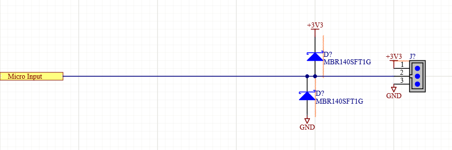
This is ‘ok’, but it relies on not connecting anything that can supply a ton of current.
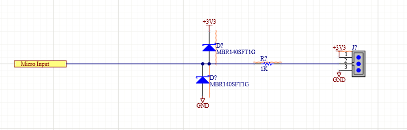
This is better because it has a 1K resistor to limit that current, so likely anything up to 10V is probably fine. On the other hand, the ADC won’t real accurately anymore because it’s trying to draw pulses of sample current through a 10K resistor.
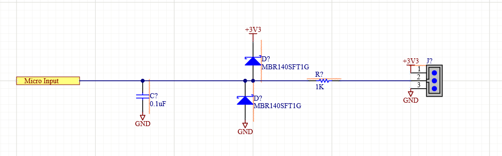
This is better because it has the 1K to limit current into the diodes and a capacitor to act as a filter/ADC buffer. The downside being this implements a 16kHz filter.
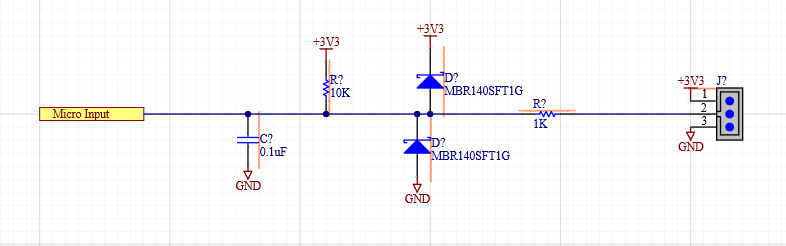
If you want to add a pull-up, adding it here will mean that you’ve created a voltage divider. 0V on the input will actually look like 330mV to the chip, because it’s a 10K and 1K voltage divider.

So this is a better way to add a pull-up. It will let a little more current flow to the 3.3V rail if a 5V signal is connected, but not enough to be concerning. It will pull up fully to 3.3V and allow the signal to go all the way down to 0V.
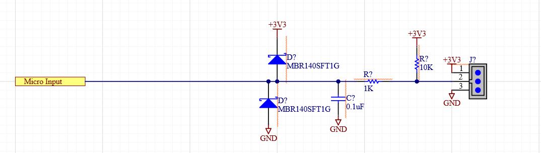
And this is how I’d do it in practice. There’s no difference in the schematic, but I’d put the resistors and capacitor as close to the connector as possible. That way any high frequency currents that are being directed to GND through that capacitor can exit back out the connector as directly as possible without crossing other parts of the board, etc.
That last one is what I’d use for measuring a thermistor, just with the pull-up changed to being a suitable value for the thermistor, based on the range of temperatures I’d be measuring. Usually your highest resolution measurement for the thermistor is when the pull-up matches the thermistor value. That’s when the smallest change in thermistor value leads to the highest change in voltage/ADC counts. That may make other extremes less accurate, though, so I normally calculate both the expected voltage and the expected dV/dTemp at the extremes.
1 Like
That would only work if there were something else added to act as a resistor to ground, too. Otherwise all the thermistor is doing is being a variable value pull-up, but it would always still pull up to 3.3V.
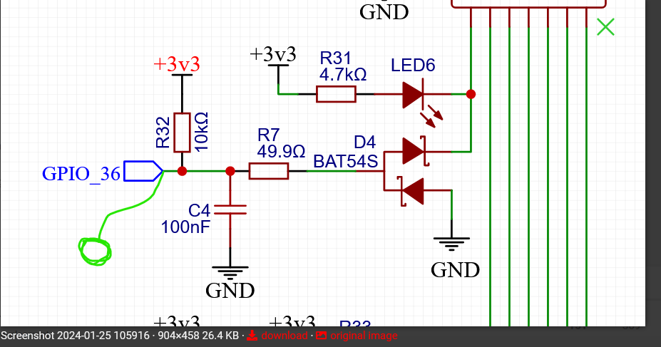
The easiest thing to do would be to add a bit of wire or a blob of solder across 2 of the pins of D4. Or remove D4 completely and blob some solder on.
2 Likes
Easy enough to test once this is wired up. If you think there is a chance it works, as long as we are within 2-3C that is plenty good. If not we go the other way. The downside is I have to choose where to put those 3 analog pins on the pico.
![]()
Thank you for doing that so clearly. EE 101. I almost completely understand it.
This is sooooo close to how it is, the Diode is just rotated, a different value of resistor. I might just be able to reroute it. I need to really look at this. And read it three more times.
2 Likes
ok, I’m way past my safe zone in the shallow end with this ocean swim here… but Im just thinking outloud.
A while back I was looking into taking an old laptop and booting it linux to not be 1 RPi, but SEVERAL. So in that spirit, why not run a min LAN of sorts with a dedicated klipper laptop from the back of your junk drawer hooked to any and all of your machines at the same time. Then hide it in the work bench and use your actually computer to wifi into the various Klipper instances running on the old laptop?
Then I started looking at cheap $50 wally world tablets with enough processing power to do the same thing in a much smaller package.
But like I said, I’m out way too far in the deep end here.
EDIT:
Advantage of running the hard LAN means the output pin numbers are no longer an issue. You can make them whatever you want them to be with just a soldering iron.
I have no idea how fast things would work on a printer / CNC Nothing is that fast other than step pulses right? 10khz seems super reasonable and like it should have lots of overheard…there are other ADC pins that are not limited on the ESP (the pico could have two adc over in the usual inputs, and one naked one to the expansion headed or the adapter board).
The components are as physically close to the pins as they can possibly be now.
Will your way still drive that indicator LED?
I was wondering about the print farm as well. the latest Teaching Tech video about a cheap Klipper screen seemed to make it look easy to just swap between printers on the one screen, $10
1 Like
I wouldn’t think so, no. Even then, those signals are digital which means you can reduce the capacitance. The capacitance only needs to be that big because the ADC needs pulses of current when it samples because of how it works. The digital inputs just look at the voltage constantly and don’t have the same issue.
I wouldn’t add the LED if it’s going to be used as a thermistor/analog input. The current through the LED will act like you’re taking the value of the pull-up and changing it. Usually I like to separate analog inputs and digital inputs because it’s a bit challenging to make circuitry that does the job well for both of them. Then again, I’m usually designing stuff that’s way more ‘single purpose’ so I typically know what is getting connected where at design time and can design accordingly. If you were dead set on keeping the input able to digital/analog input with an LED for state, I’d switch to using something like a FET to drive the LED and then all you’re hooking up to the analog input is the gate of the FET which won’t use much current or upset the circuit at all.
1 Like
For your print farm you could get one of the cheap HP micro computers off ebay like @turbinbjorn has and run all 8 of your printers from one computer. Just need you a decent USB header lol
1 Like
Okay, that is okay. I can send them to the top of the pico adapter. If we find a good reason we can send them to the expansion header. The CNC/esp32 side doesn’t need it at all since we already have four free pins that can be anything at the module header.
1 Like
Wow, there are a lot of replies stacking up.
I’ll try to answer and also elaborate a bit.
I’m not using things on Jackpot that I see which are already not suitable as-is for an alternate use. See all the discussion above about thermistors, for example.
For your situation, I’m also deliberately trying to propose design options where you can leverage open source things that already exist. So, for example if a bunch of boards are using a specific circuit with 3.3V IO, (again, see the thermistor example) using that same reference circuit means you don’t have to do time consuming and error-prone tasks like figuring out how to model and describe your own circuit. So it gets really much easier to use existing configurations or code. There’s no one for you to have to hire or to beg to contribute code. You don’t have to exhaustively vet the circuit. Others are already using it.
Using an existing reference circuit design also makes it easy for someone with a need or desire to contribute code or configurations.
I also am looking with my own slant on requirements for the hypothetical V1 designed RP2040 MCU in a package that is roughly ESP32 form factor and IO compatible. That may make for some good discussion, so I’ll go into some detail of what I see there.
-
Be able to swap this board into a jackpot, and have it usable for a 3D printer running Klipper on the jackpot with as few changes as possible to the jackpot. (This is doable, by the way).
-
Make use of the FluidNC board heritage that uses what is a fairly unique implementation for the way the TMC2209s are interfaced. Using a gate on some uarts and the I2C muxed IO doesn’t have an equivalent in the Klipper world- so this part should at least make some sane choices in which of the available IO on the RP2040 gets routed to the Jackpot TMC design.
-
Remain able to use Bart’s IO expansion header that you left on the jackpot.
-
If possible, maximize the utility of the rest of the jackpot board (e.g. my note about maybe wanting a header or jumpers and a header for the IO that presently goes to endstops, 5V IO, or the low side switched FETs.)
-
Be able to use the microcontroller board by itself, standalone. It would be a klipper target- a utility controller to expand a users existing build. This is part of why I propose adding some additional IO on top that may be duplicated compared to the jackpot. I’m still thinking this through. But this is really ideal for someone wanting to add an accelerometer, or a bunch of sensors, or drive some FETs. Want to add a filament changer but not enough IO- stick in a V1 RP2040 module and hook the stuff up. That kind of thing is an additional use case. In this use, the board is not to build out a whole printer. It would just expand an existing printer that ran out of IO for the few things that their existing controllers have available.
Yes, it’s a bit weird as an example to have some headers or connectors on top of the MCU that someone could plug thermistors into, or maybe connect some external SSRs, or a free UART. But this is exactly what that standalone use case wants. NOTE: If we do this thoughtfully, that IO could also “Finish out” making a Jackpot into a credible single-board solution.
I also don’t necessarily think you have to buy a Pico and then try to solder it in to a board to adapt it to the footprint of the ESP32. You and this community proved remarkably capable of making your own ESP32 dev board to put in jackpot. So much so that I think you should consider an alternative.
Why not consider building your own RP2040 board? Starting with the RP2040 chip and other elements of the reference design, but instead packaged and extended as we’re discussing to target those headers on the jackpot. So you could have headers and IO on the top side, as an example- to make it just the right fit for your application. Maybe it’s not possible to go below the cost of an off the shelf pico, but I’ve heard that the RP2040 is ridiculously affordable- so maybe instead of having to do an extra board, extra assembly ops to solder in those pico castelated pads, just make your own board outright.
Doing this also meets that suggestion above that the V1 RP2040 klipper microcontroller is suitable for Klipper users in the expansion case I described.
As I’m thinking about all that, I’m also thinking about some of the “what if” type stuff. For example, if you put in IO, jumpers and assorted items that lets someone set up a soft CAN implementation, that might be super high use to the user. There are probably others. Are there any thing a Klipper CNC router user might want?
I haven’t finalized all my thinking about what the requirements are/might be for this little gem- but that’s why I’ve proposed some things that might seem counter intuitive.
I don’t think I necessarily have the answers that work for you. My observation is that this community finds its way to a good place if we work together to talk it all through so you can decide what path to take.
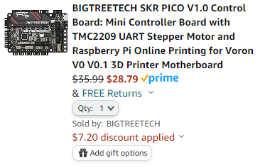
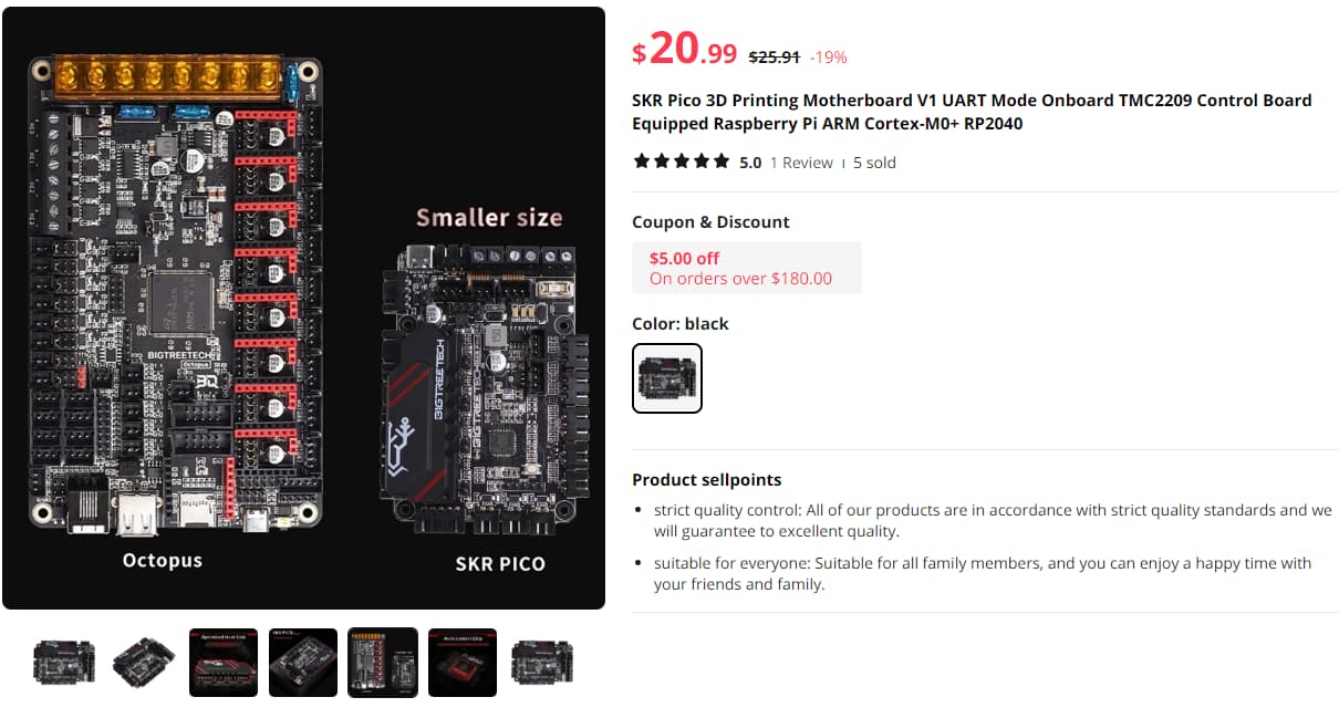
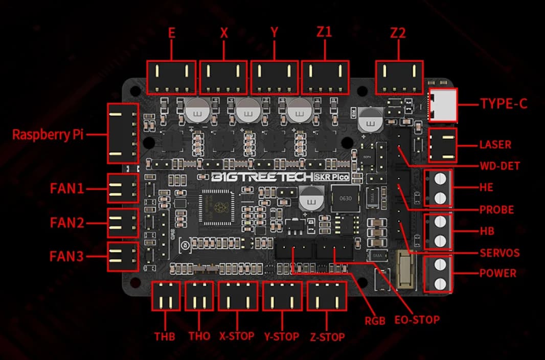
Already seen this Klipper PICO board? 5 Stepper Drivers directly on the board, could handle motion, and, IF CAN Bus could be connected somehow (e.g. PI → USB CAN module → EBB36/42 or similar), then the Extruder Assembly’s break out board (EBB36) will have embedded TMC2209 for the extruder?
https://github.com/bigtreetech/SKR-Pico/blob/master/Hardware/BTT%20SKR%20Pico%20V1.0-SCH.pdf
https://biqu.equipment/products/btt-skr-pico-v1-0?_pos=1&_sid=629ae3639&_ss=r
https://www.amazon.com/BIGTREETECH-PICO-V1-0-Control-Board/dp/B09MYKL9MP
https://www.aliexpress.com/i/3256803793957612.html?gatewayAdapt=4itemAdapt
Like the compact mounting…
Has RGB too…
Don’t know if Raspberry Pi 3/4/5/Zero can support CAN Bus via GPIO directly, or, whether you’d need some SPI to CAN transceiver module, e.g. something like https://www.adafruit.com/search?q=MCP26525+. I don’t know much, haven’t researched much…
That would be simple if we can prove this works, and figure out the TMC expander on here.
At that point decisions could be made about what is needed and what isn’t (7 inputs are a no-go we really only need 2-3, some might want to use some of those for sensorless homing or other type of inputs).
We have a complete board, and for about $10 we could have a dev board to work out all the issues with. Heck, you can slap this pico onto a 6 Pack Controller and have anything you really want (except 6 TMC steppers).
From that point does it make sense to try and compete with BTT/biqu? They already make fantastic boards for a great price that do everything and have international shipping that cost like $2. I will never be able to compete. So why try, I think my time is better spent having a bit of fun with this and then getting back to the CNC world (before Biqu starts making those as well).
I have a CNC board that I will be using a lot of. I enjoy building 3D printers as a hobby. I think it would be really cool to combine the two. Is it better than any other board out there, nope, is any other board out there this cool, nope. I do not think there is ever going to be room for me to try and sell a 3D printer, or a 3D printer control board. But for ~$10 I bet a couple of you will try out a jackpot as your 3D MP3DP engine, for the cool factor. So any time I spend on either needs to be carefully considered as to not take away too much from my CNC focus.
4 Likes
I was wrong, BTT’s pico has 4 Steppers. Two Z connectors to same driver. So, no good for a mp3dp as-is. Also, product reviews (Biqu and amzn websites) comment on various board issues (screw terminals fragility, layout/component concerns, etc…). That said, hopefully their design/features/schematic sparks some ideas.
1 Like
https://www.youtube.com/watch?v=R3o0MGYW1ZU&t=602s okay so the screen is here, install is simple. The way it works is drop all your printers onto the same network and it looks like this one screen can pick them all up, or maybe only one, not sure. But if that is the case, I can just use my shop tablet as well. Looks like I am ready for klipper other than a printer!
3 Likes
Too bad we can’t run klipper screen on a tft35. Have plenty of those laying around lol
Either way if you set up your farm all on klipper you could go out and clear all your beds then go sit at the computer and fire every one of them up without ever needing a screen. But I have to say the screen still is nice to have.
I like the raspberry pi header connection on the board so it connects on like a shield. if the power from the skr power source of 12 or 24 v in are regulated to power the raspberry pi, that would be pretty cool so you wouldn’ t need to source a 5 V power supply or converter in addition to the printer power supply. too bad that board only has 4 drivers, but it has 5 plugs. Looks very much like the skr E3V3.
@jonathjon I have a TFT35 as well and I was just looking at using it somehow. The best I’ve seen done is to put it in marlin mode and have it emulate a 12480 LCD or the reprap 5790 or whatever number that budget LCD is.
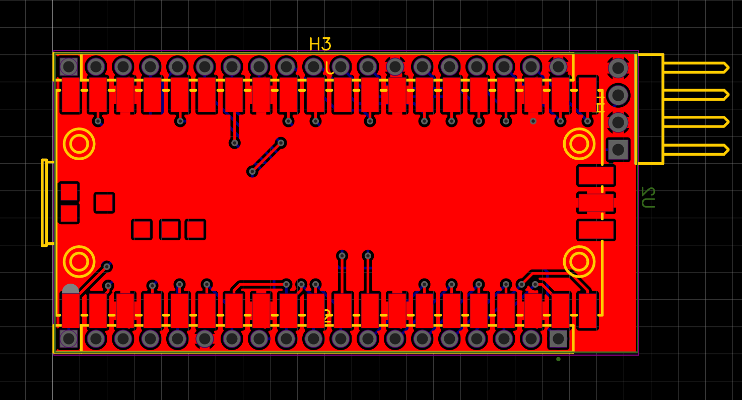
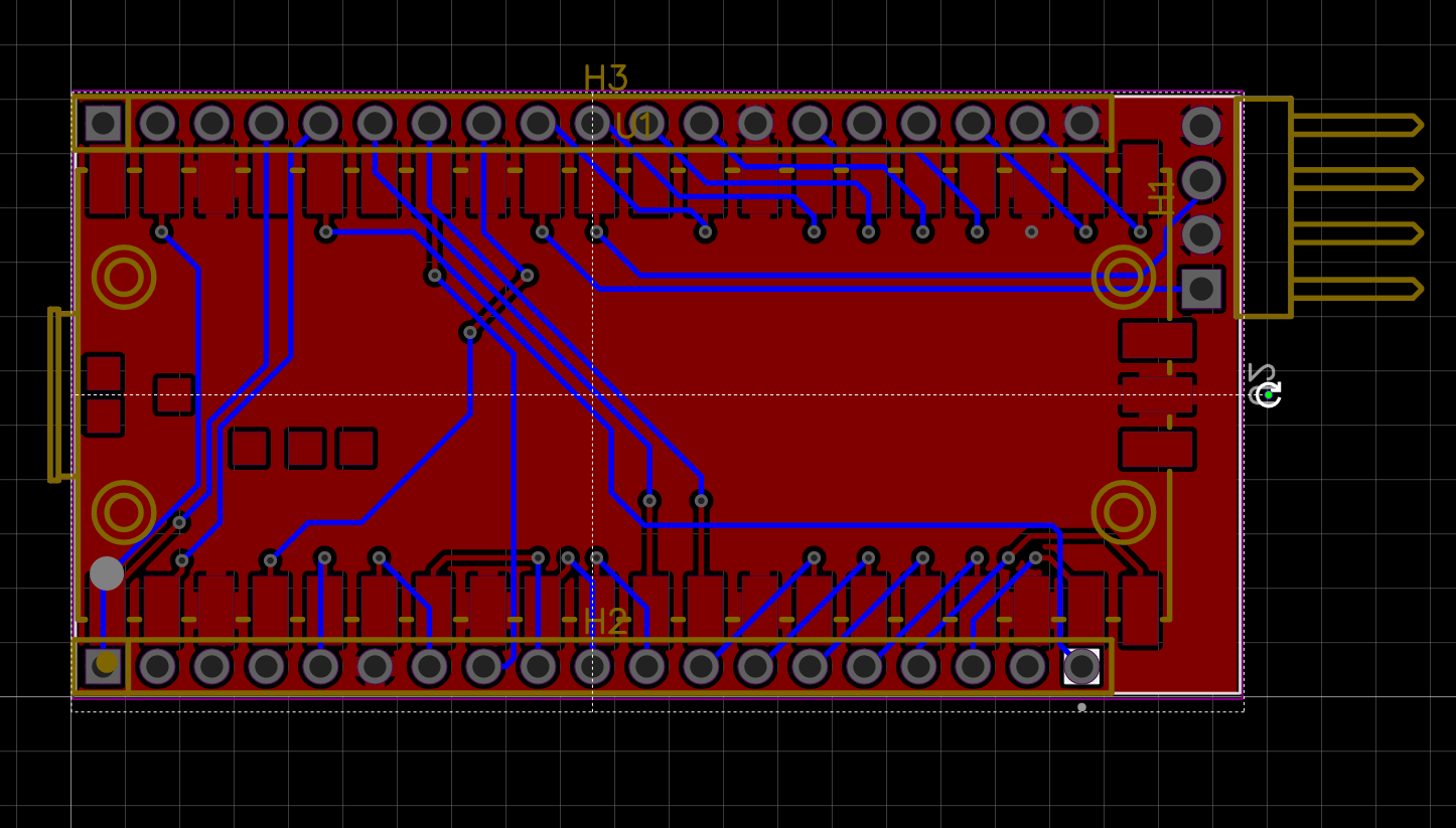
You could use a board-edge connector / adapter so that your new Pico board sits perpendicular to the ESP pins/board. It would require two boards. One with the socket and all the traces connecting the socket to the ESP pins. Then another board with your pico and any new electronics:
1 Like
Nintendo style!
1 Like