Klipper + Jackpot?

No, all 6 use the same UART interface. Three are direct, three use a gate to switch the UART to the TMC.

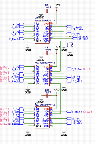
But ALL of the enable/step/direction IO goes through a shift register based GPIO expander.

The uniqe parts are the shfit register expander, and then the gate control for the three stepper drivers that use it.

Without the expansion, NONE of the TMCs will be usable for motion.

2 Likes

PIO implementation of the GPIO expander. It should be possible, note the following from the RPi documentation

The programmable input/output block (PIO) is a versatile hardware interface. It can support a variety of IO standards,
including:
• 8080 and 6800 parallel bus
• I2C
• 3-pin I2S
• SDIO
• SPI, DSPI, QSPI
• UART
• DVI or VGA (via resistor DAC)
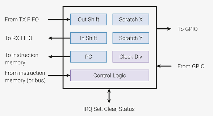
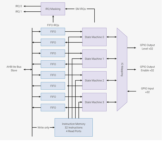
PIO is programmable in the same sense as a processor. There are two PIO blocks with four state machines each, that
can independently execute sequential programs to manipulate GPIOs and transfer data. Unlike a general purpose
processor, PIO state machines are highly specialised for IO, with a focus on determinism, precise timing, and close
integration with fixed-function hardware. Each state machine is equipped with:
• Two 32-bit shift registers – either direction, any shift count
• Two 32-bit scratch registers
• 4×32-bit bus FIFO in each direction (TX/RX), reconfigurable as 8×32 in a single direction
• Fractional clock divider (16 integer, 8 fractional bits)

From here:

I think the implementation would define on the Pico side of things a GPIO map of the GPIO expander, such that the Klipper host can use this pin map to command toggles. The PIO code would then implement clocking out the GPIO state table through the PIO’s over to the shift register chips on the Jackpot.

2 Likes

So this is something that needs to be programmed though ssh, and then once that’s done use the corresponding gpio numbers in the printer.cfg in klipper? Just making sure I’m following you correctly

1 Like

The implementation I describe above would need to reside in the embedded code that runs on the target. This would probably be a .UF2 file that needs to be loaded on the Pico. I don’t know if Klipper can push the UF2 automagically over USB as I don’t (yet) have a Pico target with a Klipper host. That is probably how it works in practice, though.

You’d command the build process over SSH to the Klipper host, but all of this lives inside the embedded implementation on the microcontroller target. Creating the code implementation for pushing over the GPIO state table is code that lives wherever you build the target, and this ends up in the binary that gets loaded to the Pico over USB when it is being programmed.

After loading the embedded code, the Klipper host would be commanding changes to the GPIO map and letting the PIOs in the Pico manage the bit-banging process to get the GPIO expanders to do the right thing.

1 Like

Remeber, I know nothing…are we sure we can’t just use SPI?

I don’t think so. The Klipper host (Raspberry Pi or other SBC) has to talk USB1 over to the Pico, so there’s no SPI present there.

The implementation of the GPIO expander on the Jackpot has to use the native interface of the shift register ICs. Those use I2S WS and BCK signals (MR# is just pulled high on the Jackpot, so you only need those two signals.)

None of that looks like SPI to me.

Looking at the chips it doesn’t mention any protocol, just that it needs 3 pins. Nexperia 74AHCT595PW,118 Datasheet

So we can’t use just spi to the chips instead of having the pico convert spi to i2s first?

I guess, It sounds like you are saying the pico can’t run spi and usb at the same time? So it doesn’t matter if the chips can’t off SPI?

At the most basic level I am just seeing spi and i2s only differ by how they use the clock signal.

No, it’s a bit different than that. I’ll try a different description.

Klipper host talks to the embedded microcontroller, and on the Pico this has to be done over USB1 unless you want to hook up a UART from the Pico over to the Klipper host (You dont want to :slight_smile: ). This limits you to 12Mbps USB1 speeds because that’s all the Pico can do. [This is the major failing in the Pico in my opinion- if only that this were USB2… Maybe for Pico 2 that’ll get fixed]

At any rate, the best way to do this would be for Klipper to tell the Pico “Toggle bit 24 on the GPIO expander”. Over on the Pico side of things, it gets that direction and then goes about shuffling all the 24 bits plus other stuff that the shift register needs. All of the bits have to be clocked through the shift registers and then asserted, each time you want to change the state of any one bit.

If you wrote something on the Pico that lets the host Klipper directly access the two pins on the Pico, then instead of telling the Pico “Toggle bit 24 on the GPIO”, Klipper would instead have to go through the entire sequence of clocking the bits into the shift register. The sentence would instead be something like “Send this bit, then that bit, then this other bit…” and so on. This would expand into something perhaps 30 or so times more volume of traffic than just telling the PIco to change one bit.

Edit to add: The command to change that bit also has overhead. Imagine that you can fit the wrapper for that command into say 32 bits. To pump out all of those 30ish bits of shift register commands, each command has to be wrapped in that example 32 bit command. So to make the math easy, you have 12Mbps of the USB1 bus divided by (32 bits times 32 bits) . You’ve turned 12Mbps of interface into 12K commands per second. Those steppers need hundreds of thousands of commands per second when they’re all moving. The system can’t work at reasonable speeds. It would be a turtle of a controller.

All this extra overhead starts to severely limit how fast you can toggle the step/dir/enable bits, and thus starts severely limiting the speeds you can get out of the motors. It also puts a heavier load on the host Klipper and that crappy slow USB1 bus.

So even if the shift register ICs can speak “Whatever”, you still want to use the PIOs on the Pico for the heavy lifting of continuously clocking out the bit pattern of the GPIO state.

That’s I think what most folks miss when trying to think about the GPIO expander. You never send just one bit to the stack. To command a single step bit to one stepper driver, the entire set of bits for every single outpot on all of the GPIO ICs needs to be sent. Every single time any bit changes.
2 Likes

Sounds like we need to understand Klipper config, and more deeply the command based protocol between Klipper host and Microcontrollers like Pico.

To minimize traffic over USB, we need to understand if the protocol already supports sending just command indicating delta operations. With the microcontroller holding a buffer of state used to send data to the GPIO expanders?

I don’t understand TMC2209’s UART stepper protocol enough. Am mainly reading along and learning, thank you!

1 Like

Okay, Okay I get it now. Thank you, it is clear in my head.

So we need klipper firmware to talk to a special “software embeded chip”. I don’t know how to say that, I know it is not a real chip, but we need the pico (or really any board) to have a section added to deal with multiplexing. Kinda like Configuration reference - Klipper documentation.

So when we generate the pico’s UF2 (firmware?) file it knows to do the expanding in that side. The big klipper pi board still just sends motion commands over the (usb1 bottleneck) and the Pico expands it.

I am learning a lot here for a Sunday…

I am assuming the [expander] section would just define map the three pins, and the [stepper] sections would still list the i2s/spi equivalent pins.

Okay?? If that is the case, does any one here think they can work it out or do I need to see if I can use the one klipper connection I have to find a klipper dev?

I know in my head the “What to do” part of it, but I don’t have the coding skills nor style / implementation preferences that the Klipper side needs. So I could help describe the problem but not create the solution.

It’s a good time to be reaching out to the Klipper community and maybe also to the Pico community.

The venn diagram of PIO developers who also have a Klipper 3D printer has to have some overlap. That’s the pool of people with ready access to the skills needed to do this.

1 Like

From Klipper forum…

1 Like

That takes it right back full circle to why they advise against using GPIO expanders for fast IO, which is exactly what I’ve been describing above. You need the embedded side state machine to avoid the problem they identify in post #2 of that forum topic:

From the documentation: “Due to the delay incurred by I2C communication you should NOT use SX1509 pins as stepper enable, step or dir pins or any other pin that requires fast bit-banging.”

1 Like

Let me see if I can bring in some outside help.

1 Like
  1. I don’t agree that the USB is slow. Klipper has a very good protocol for communicating things in a queue and the steps are done on the MCU. You don’t have to command every edge on the STEP pin over the USB. Marlin handles gcode on a 112kbps connection, 12Mbps is like living in the future.
  2. I don’t think you need to mess with the PIO expander either. This isn’t fast stuff like neopixels. It is easily handled by regular interrupts. It might be nice, to reduce the overhead on the pico. But definitely not a requirement.
  3. If no one at klipper has developed a way to configure the gpio expander on the jackpot, then we need to edit the firmware. This should be code in the pico klipper firmware that takes configuration parameters from klipper host and then responds to the klipper protocol messages by setting the jackpot expander correctly. I am specifically not mentioning spi/i2c because it doesn’t really matter what the protocol is (and if it is just a shift register, then it is neither spi or i2c). Whatever the chips needs has to be configured in the klipper firmware by klipper host.

I’ve opened Aza’s link. I’ll read through that. I am pretty sure I could fumble through making something that worked (and it would be pretty fun and frustrating). But making something good in embedded C++ is not something I’ve had great success at. I was really hoping someone had figured out this issue with another board and the klipper firmware already supported it. Still, this is easier than converting all the klipper firmware to the esp, which would have needed the same kind of talent and 10x the work.

3 Likes

I read Aza’s link (I didn’t realize it would be so short) and that won’t work. We need the gpio expander to be controlled by the firmware so the stepping functions and trapezoid movement control happens on the pico, not the host.

2 Likes

That’s not really the correct comparison, though, is it? A gcode sender is what passes the gcode into Marlin (or a reader, in the case of local filesystem). That doesn’t have to be fast becase the interpreter and kinematics live inside the microcontroller on a Marlin system. Inside that system, the interface between the interpreter and the kinematics and low level drivers are much faster. That’s the interface speed we’re comparing.

It may well be that a simple process in one of the Pico cores could handle the necessary translation of step commands into shift register bit banging. It won’t be nearly as performant as a PIO would be, but perhaps it’s plenty fast enough.

We completely agree on this. That’s the task at hand. No one has developed an implementation for the shift register style that the Jackpot uses.

A slightly lesser task would be to create an implementation to handle the funky gating of the UART for the 3 stepper drivers that share an address. We need that down in the Pico to allow all 6 TMCs to be available to the Klipper host.

I see we agree. :smiley:

Have you read the kinematics and protocol that aza posted:

You’ll like it. The protocol is tight and it works on an arduino mega just fine, which has a uart between usb and the micro.

Yeah. Once we’ve edited anything, that will be easy.

3 Likes

I have started. It has stepper queueing commands like that quoted below. In our example, this would mean the implementation in the Pico would need to take these and generate the pulse train for the steppers as defined by the message.

That implementation would need to manage the bit-banging of the 6 stepper drivers’ EN/DIR/STEP signals which are interleaved in the 3x 8bit shift registers.

I’m still reading to figure out if there’s a command definition that replaces the strings below with function numbers. It may, which would be more bit-efficient than passing the strings- but perhaps that doesn’t matter.

As long as the work to manage the pulse trains through the expanders are done in the MCU, this works great. That isn’t what the GPIO expander support like for a MCP23017 mentioned up thread did- that just gave the Klipper HOST a low-level way to set a GPIO expander bit set. E.g. the type of interface you’d use to light up a status LED or to read a non-timing-critical switch via GPIO input.

As soon as there is MCU side ability to respond to the host protocol by clocking out to the shift register then most of the heavy lifting for Jackpot/RP2040 is done. We’re still in agreement :smiley:

3 Likes

https://www.klipper3d.org/Protocol.html#message-blocks

When I first heard of klipper, I read these docs and it is really impressive. I don’t think much of that has changed at all and it is the genius part of klipper. Doing high level planning in python on a SBC and then just shuttling the real time work to the MCU is great. It lets people with math degrees write great algorithms on the squishy python side and hard core embedded bit bangers control timing to a hairline on the MCU side. So much of the development is easier with this protocol and kinematics. They have a neat clock measuring tool too that estimates and syncs the python and mcu clocks. And if you like CAN, you can move some of the functionality to another MCU and they will also stay synched. Good stuff.

I haven’t ever tried to compile it or even read the code though. I have no idea how hard that will be. I assume there will be many examples of what to do though.

3 Likes