You guys are giving me hope, that is about all I understand of that so far. But I am learning slowly.
1 Like
Glad it’s not just me. Like trying to read a foreign language for the first time lol. But I’m following some of it lol
Just got me a shiny blue jackpot board so it made me curious if anyone has been able to make any headway on getting all this voodoo figured out.
1 Like
I was trying to see if there was an update, but I’m 150ish posts behind. Lol. Just message me when to send my money.
1 Like
I think there’s a V1E special test board on its way to me right now and expected any day now. It’s a RPi Pico dev board placed in the footprint of the ESP32.
I’ll start playing with that when I get it, but the next step really is to have help to get the Jackpot style GPIO expansion properly supported in the MCU embedded target for the RP2040.
Long-winded way of saying this is all still WIP and experimental.
4 Likes
I want to try that pretty bad, but Have too many irons in the fire to be much use or help on it.
2 Likes
I did reach out and, no devs were recommended. So it looks like if we get close we just have to use github or discord.
2 Likes
This is knida making me wonder if I could run it through my Sonic Pad. Hmmmmmmm
Someone was nice enough to ship me a rp2040 in the shape of an ESP32. I always assume there are no strings attached with Ryan, but I am a curious person, so I am looking at this today.
I’m going to dump some notes on it here. There are several ways to look at this, and a few issues we have to solve for this to function at all.
Stepping (DRV8825 functionality)
Looking at the Jackpot Schematic, there are three 8 bit shift registers 74AHCT595PW,118 datasheet. They control step, dir, enable for X, Y, Z, A, B, and a few things related to the TMC UARTs. The inputs (DS on U2) are labelled I2S, but these are regular shift registers. You set DS to the value to want to add in, toggle the SHCP (clock) and the shift register saves that. The Serial Output (Q7S) from U2 is the Serial Input (DS) on U3, etc. So to set all three registers, you need 8x3=24 clock cycles. Once they are set, you output all of them at once using STCP. That is some of reading the datasheet, and some memory, so I may have some of it wrong. I don’t know I2S well, but I don’t think that is how I2S works, so I assume those are just the wrong labels.
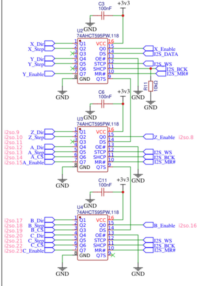
In the klipper firmware, any time any of the stepper GPIO (en, dir, or especially step) need to toggle, all 24 registers need to be written out.
The klipper firmware is trying to be very tight in stepping (understandably). I think this is one place we could inject our own step gpio command:
gpio_out_toggle_noirq certainly sounds like it is toggling that output right-freakin-now and won’t wait for some interrupt. If we replaced that with the shift register routine, we could step there and we would get motion.
We would have to have a copy of what all the outputs should be in our own 24bits of memory, and when gpio_out was called, update our little memory and then flush the 24 bits to the shift registers.
The trouble is, there is other code in these stepper_event_blah routines that are trying to guess on timing. I don’t know what these are doing and they are a bit scary (goto is a name I haven’t heard in a long time). The likely and unlikely look like they are trying to decide if the next step is going to happen before the next stepper_event.
The dir, en pins also need to be configured to run through the shift register. They need a similar little routine to toggle a pin and flush the shift registers.
The good news (w.r.t. timing) is that this is a fast processor and toggling 24 bits may seem like it would take a lot longer than toggling one (and it does, in mcu time), but it will still be really fast, because it is a computer.
UART (TMC Configuration)
If we managed to just get the above working, could we plop in some drv8825s and just step without messing with the UART? Probably not. The MS pins on those driver ports control the microstepping selection in drv8825s. They are hard wired to different values for different drivers, to allow for different driver addresses on the shared UART:
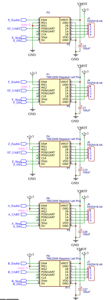
We can change the state of ST_UART, but we can’t change the 3.3V or 0V connections on the jackpot (easily).
It looks like Klipper can send UART over the same wire. I’m not 100% sure of that, but I see signs like config variables named TU_SINGLE_WIRE. But FluidNC has gone a step further and made drivers A,B,C on one address, and multiplexes them:
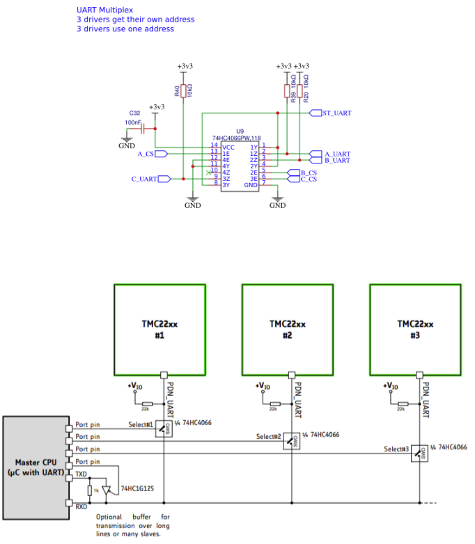
So, before Klipper configures ports A, B, and C, we have to set the shift register for A_CS, B_CS, or C_CS correctly, flush the shift register, and then the Klipper UART routine should work. I think that code might be here:
I don’t see any way to block multiple drivers configuring at once. I hope that is handled in the linux/python side and they only send/receive for one driver at a time.
Once we have it working, there is a lot of code between the tmcuart.c and the yaml file. All of that would have to be updated to allow a user to configure the jackpot with these extra UART/shift register steps. There may be sanity checks to avoid having multiple drivers on one address. Or there may be support for multiplexing multiple UARTs on one wire using the configuration already.
2 Likes
This is part of the chip specific implementations. The rp2040 implementation is here:
The gpio_out struct currently only contains a “bit”. Which is actually a uint32…
Maybe that is a mask for which pins to toggle? Maybe we could make that also have a flag to indicate if this bit is part of the regular gpio, or part of the shift register.
The other functions in gpio.c can probably also be updated for the shift register code. gpio_out_toggle just references gpio_out_toggle_noirq, so that doesn’t have to change. gpio_out_write and gpio_in_blah need to be fixed updated for the shift register. If we did that, I bet en and dir functions would work immediately.
3 Likes
Yeah, likely to be really fast. I’ll reassert that if it isn’t fast enough, the PIOs in the RP2040 could provide a memory mapped space for the bits, and the PIOs could handle clocking out the data, offloading the rest of the RP2040. You’ve previously pointed out this may not be required from a performance standpoint- which I agree with.
If passing the shift register output is accelerated by a different part of the hardware, the underlying premise that things are essentially instantaneous would still hold, right?
I suppose the question in all of this is just how long it actually takes to clock out those 24 bits of state to the shift registers and assert them, compared to toggling a GPIO in a ‘normal’ implementation.
How fast are the clocks out to the shift register?
2 Likes
Maybe, but if it isn’t actually faster in the PIO, and the main thread wants to toggle it again, then we will have to block until the first is finished, and we will be at the same problem.

Very fast. 90MHz at extreme temperatures (over 85C) sounds pretty darn quick. The rp2040’s clock is 133MHz, so we can probably get away with just setting the DS and toggling the clock, without worrying about any delays.
Let me do some math “out loud” here:
100mm/s (good goal), 100 microsteps per mm would be 10kHz stepping rate. I don’t have the spec for the drivers, but that may mean 10k edges per second, or 10kHz. I’m not sure, but 10kHz would be worse. The Z on the MPCNC is 400 steps/mm, so 40kHz.
If we are toggling all 6 pins at the worst case scenario of 40kHz, and we are toggling all 24 bits for each of those steps (not optimizing for multiple step pins at once), we would need to toggle the clock at 40kHz * 24bits * 6 steppers = 5760kHz. That’s getting up there. The limit won’t be the shift registers, it will be on the rp2040, if there is a bottle neck at all. But, it may still be fine. All of the complex math is done in Python on the host to give the max amount of time for the MCU to step.
That’s all pretty conservative though. The reality is that we won’t have 400 steps/mm or need to move at 100mm/s on all axis at once. I am also pretty sure we only need to have edges for step, which is 5kHz at 100mm/s for 100 steps/mm. Z won’t need to move at 100mm/s either.
5kHz * 24 bits * 6 steppers = 720kHz. That leaves a lot more room. I don’t think we have to nail it either. If we miss the mark, I bet it would just slow down a bit.
I’m not sure if I have to worry about all that likely/unlikely stuff or not.
For a first iteration, it would be good to just make it easier and go slower. Faster would be a stretch goal after the MVP.
I tried compiling the firmware as is on my Linux machine, and it wants to install some dependencies… Grumble. That’s expected, I guess. I should spin up a docker container to get a building env that won’t break my computer.
2 Likes
If you spin up a docker build environment, share your notes ![]()
2 Likes
A certain some one sent me a dead Jackpot and a shiny new ESP-32 dev kit shaped RP2040 thingy.
I fixed the jackpot, so I’m chomping at the bit to put some test firmware on the RP2040 test adapter.
1 Like
Obviously, I only understand a couple of those words very well.
Now that you have taken a deep dive there are a few options.
- Is it worth it at all? Sounds like it is more complicated than I thought, or does it not seem that bad?
- Do you see another way to do this in terms of board design, this was done to save a some pins on the ESP32. We can normally only get 4 drivers per UART, so we would have to give up 2(?) out of the pins on the expansion header to do it the normal way, or does it take more?
I just thought this would be super cool to do, but I do not see this taking over the scene. I love all the learning this has forced me into, but if this is not fun for you don’t push too hard.
I guess really in the end my goal is just to get the best bang for the buck out of a controller and if we can run fluid and klipper it would be really cool. If that means making a new board I am not against it.
So what if we used the pins and no multiplexing for the UARTS and multiplexed the inputs or outputs instead?? I feel like the inputs are so rarely used and they take up 7 pins.
If the scheme to clock the GPIO actually works, it seems this would allow having a really simple way to put Klipper on the Jackpot.
A really clever next spin of the Jackpot might lay things out such that you have two header sets on the board. One header accepts an ESP32 dev board and is exactly as we have it now. The other footprint accepts a stock RP2040 board.
Route the GPIO on the ESP32 and Pico dev boards differently- mapping the TMC drivers conventionally to the IO on the RP2040. Leave the ESP32 with the shift register. We’d need to count pins to confirm there is enough of the right kind of GPIO on the RP2040 pico dev board.
In this latter scenario, we’d need to make sure that the shift registers are happy when not used and the outputs are back driven driven by the RP2040 GPIO. IIRC the shift registers default to being tri-stated- so that would be fine.
The alternate layout seems like a lot of work, but one could imagine some other potential perks. Like adding one or two more bart-style expansion ports. (Imagine a thermistor or heater FET module as we’ve talked about previously)
No idea if it would be worth it to you. How well is the Jackpot selling?
I’m thinking this may not be needed. There is a select_pins config value in klipper:
And that looks like it enables MCU_analog_mux, which gets activated before every send/receive in python:
and:
So again, I think if we had the gpio calls able to set the shift register, the TMC stuff might just work out of the box…
1 Like
Very well double the SKR and climbing.
That sounds very promising.
It totally depends on the “readiness level” you want in the end. My plan was to attach some steppers on my desk and make them spin around. After that, I probably wouldn’t touch it. That is low risk, low reward. If I (or Jim) gets stuck, it’s not that much of a loss.
If we wanted to run one of your printers off of it for giggles, then it would probably be about double that initial difficulty. Up to 5x.
If you wanted to convince Kevin OConnor (or whoever the gate keeper is for rp2040 code) to accept the shift register code into Klipper, that would mean everything from this low level code to the documentation would have to be fixed. And they probably wouldn’t like us messing with their clever, efficient stepper_event code. They may never accept it.
If you had some version in klipper and you wanted it to actually work well, then you’d have to do a lot more testing. That might tell you that my out loud math is way wrong, and we need to do a round of optimization on top of the initial implementation. Maybe we figure out when we have multiple steps coming soon and batch them. Or maybe the PIO could be utilized to avoid losing the main thread for too long.
If you had all of that, you’d still have to convince people that the jackpot and rp2040 was a worthwhile contender as a 3D printer board. Only then would you start making any positive (monetary) gains. IDK how much each of those steps would cost. If MakerJim is curious, me or him might do some of them for you, but we aren’t reliable enough for all of them. Someone who is would be $$$$$.
So my guess is that we have a 50% chance of hacking something together for editing the gpio to use the shift register. After that, there isn’t much benefit to moving forward. You can always ask Klipper and see what they say. They may just adopt it, who knows? It’s value is the experiment/weirdness of it. I honestly doubt it would make it into any printer, except for something weird to show at Rocky-MRRF.
1 Like
That’s possible. The timing requirements on the step is the real issue. Every other output is so slow by comparison. Except maybe the PWM outputs.
Inputs can’t be handled by a shift register. You would need a different design for that. The ESP32 has a bunch of pins that are only inputs (35-40, IIRC) so that may be why they get raw gpio pins and the step gets on the shift register.
There are many reference designs for boards out there. Many of them already support Klipper and have rp2040 or one of the stm processors. It would be easier to start with one of those, and not write any firmware (like you did with fluidnc). You just have to find something that has a good reason to be from Ryan. Maybe you take one and cut out peripherals your MP3DP doesn’t need, and add in features you think are neat. Maybe a board that supports CAN and 3 Z steppers through Klipper with an rp2040 would be something new to the market? IDK.
3 Likes