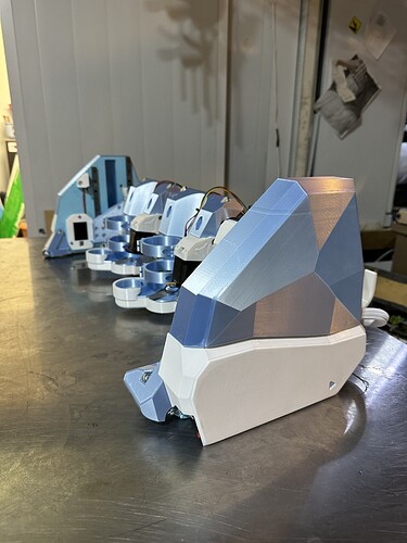
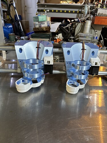
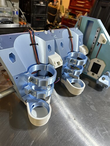
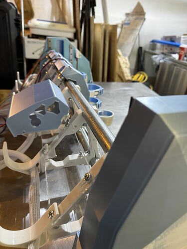
That just looks insane! (in a good way!) ![]()
![]()
We tried one of those pools and we could not seem to get enough filtration. If we set it back up I will get a proper filter for sure. It was super fun to have around, but the setup and tear down is a bummer.
That’s the biggest downside of them - they do not provide a good enough pump and filter system. Not by a long shot. I don’t think we ran our first pool more than 2 weeks before we upgraded to the big sand filter.
How do I decide/determine where to mount the Jackpot? Asking so I know where to snip the wires.
DON"T SNIP THE WIRES!
I tried that on my original Primo and ended up redoing the extensions. It’s real tempting to try and make a really neat, tidy wiring loom, but just using braided cable tubing allows the folding of the excess inside. It also allows the creation of “service loops” which provide excess to make adjustments.
Mike
Really? That’s interesting. Thanks. I’m fine not cutting as I always question my skills if troubleshooting becomes an issue. No cutting means one less place to go wrong.
The jackpots are here but I missed the doorbell so got a “pick them up tomorrow” note instead. Just have to cut and install the lead screws and then wire things up.
So I know I “floated” the idea of maybe doubling the cores earlier. After further thought I decided to just do it now rather than get everything running with a single core and then having to tear everything apart to add the second (I mean that in a relative sense - I know I wouldn’t have had to literally tear EVERYTHING apart…). I’ll pose the first question regarding this modification in the post immediately following this “pretty” post.
(I still can’t get over the facets on the fender tops…those are dead flat surfaces…)
Okay so here’s the question. I know I will need the cutters to be anywhere from 8.5" apart (for 2" cubes, allowing for .125" kerf) to 9.7" apart (for 2.3" cubes, the largest I could make efficiently) to as little as 8" for 2.5" cubes which would be not efficient for the material but if “that’s what the customer wants, that’s what the customer gets”.
With the cores touching each other the approx measurements from core center to core center is 7.0625". Which means there is room to accommodate all of the above. My question is, is there going to be a quick and easy way to switch this or will it be a bunch of messing with the belt(s) to move them closer to or further from each other?
Also, side question. I assume I only actually need the x limit switch on the left hand core actually in use? Likely obvious but had to ask anyway.
Not sure how you actually plan on doing it but how ever far apart they are when you boot up is where they will stay. If you unplug one you can park it and use the other for more room.
The biggest consequence is the loss of X working space for single-tool operation, which could mean that you really do tear everything down for a slightly longer X rail. It is not always a good idea to build extra capacity “just in case” but in this instance I think this is a good choice.
I think it’ll make more sense to me once I get the x belt in. I’ll do that next here and see what head scratching surfaces.
OK! I get it now. So here’s one for you…is there a way/room on the board and in the software to utilize both X limit switches independent of each other? If there were I could X home core (A) and then X home core (B) against core (A) and then move it a predetermined distance exactly from the first core. All it would take is a little tab hung off the X drive on core (A) to trigger the switch.
Does it need to be exact? Exact is a lot of work, moving it by hand already works, as is.
I don’t disagree. But hey, if the machine can do the work…
I can get “close enough” by making some sort of a quick block to put between the two according to the spacing I need. But actually not really - the homing core will move so I’ll have to I guess make the spacer for core B relative to the end plates, not the other core.
Or am I still overthinking things and all I need is a sharpie and a tape measure to make a mark or three on the rails to line up with before the steppers engage.
Nope. My thinking is back to the spacer block. To space between the cores. Because both X steppers will engage and core B will just follow core A through it’s homing sequence.
Wow. That was a journey through my brain there…ha!
I wonder if you could trick the firmware into thinking it was dual-X (like MPCNC) and get it to “square” the X motors using two Xmin endstops.
I dont know how FluidNC handles offsets if the endstop position is not square and you need an adjustment after homing to be square. Assuming that functionality exists, maybe that feature could establish the distance between cores.
But that’s all complicated and not recommended compared to just using a physical spacer and wiring the motors in series.
Although on second thought it would be just a config change to change spacing or change to single-spindle, and no wiring change is needed. But even then, maybe a wiring change is easier. A wiring change is definitely more intuitive.
I’m going on the assumption that the “smart” plan is to have both X steppers do the exact same thing and that then means it’s easiest to just wire them from the same output on the board - in series like you say. Which then automatically means you can’t utilize both x endstops because you can’t independently move the steppers.
I got my own wiring crossed overthinking things that are way above my pay grade. I know in theory it could be done. Absolutely. But with the build I’m setting up, the board I’m using, and the way I need the cores to behave (making exact duplicates), as Mandalorian would say - this is the way.
I’m super excited to get the jackpots and experience the interface. If I had any single grudge over all of my past and current machines it’s the “half click” on the rotary encoders that would often fire off the wrong gcode file on me forcing a reset and restart.
You can easily use a driver for each stepper. All the boards and firmware can handle that.
In my head on the jackpot you can easily use both X endstops as well, the part I am not sure about is the moving target. The main X will home, the follower will chase it, then you can easily change the offset. Just not clear on exactly what happens on the second trigger. I think they do it at the same time, so as long as your initial bump is far enough away it will work.
You just need some sort of trigger block for the Follower X to hit the endstop on. I am like 85% sure it will work.
Post a picture of your 2-off custom conformal coated jackpots!
