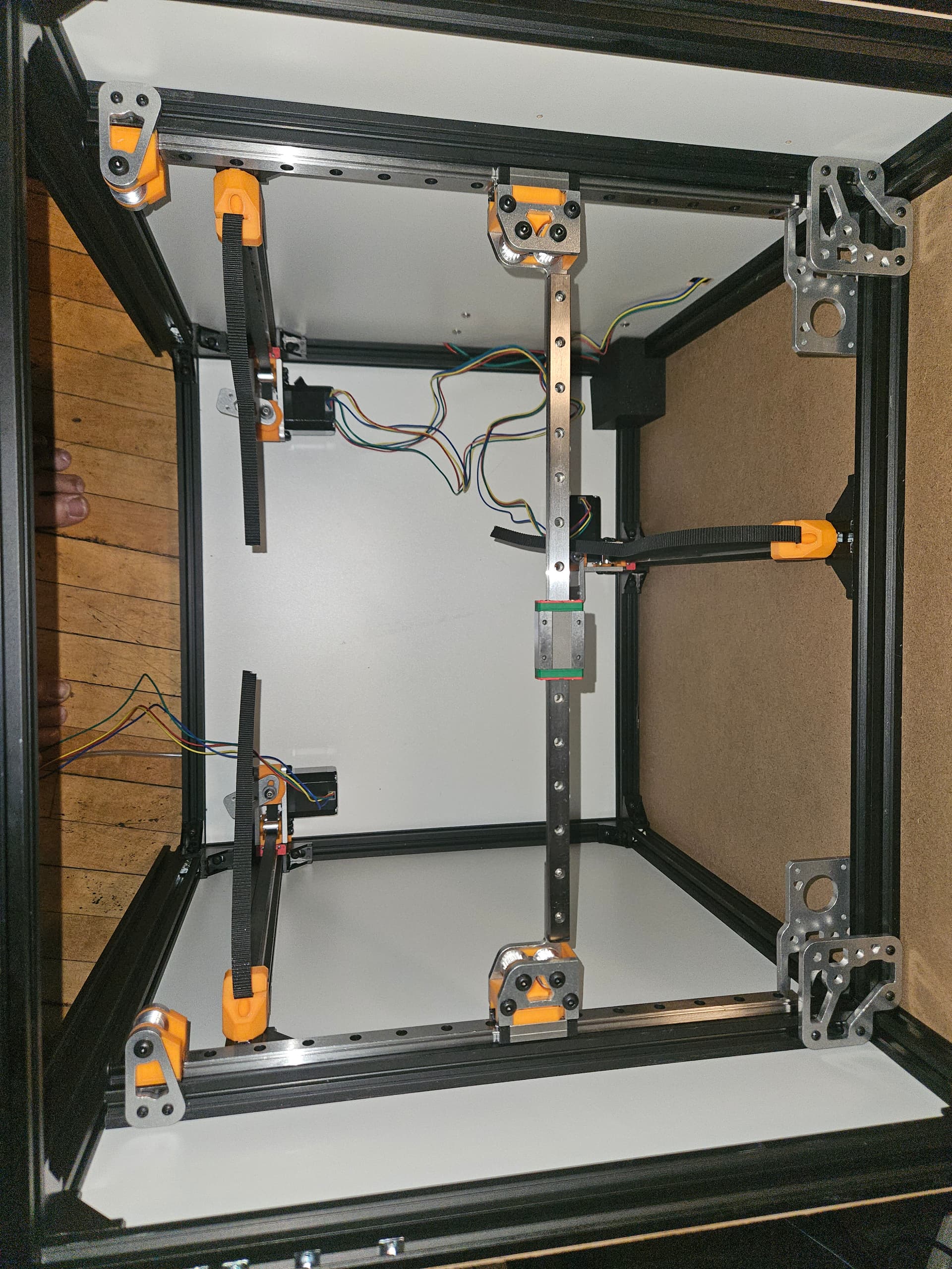
Okay… I see why it is the way it is, but I had a heck of a time with the lower corner plates. It would have been MUCH easier with the bottom panel off, but as per instructions, I installed that panel first, and it was enough trouble lining up all of the slide nuts, that I absolutely did not want to remove it. I probably should have anyway.
I got the lower corner plates installed though. the uppers are going to be annoying with the top bar in place, making it difficult to get a screwdriver straight on the screws. At least the top panel isn’t on I left a provision for the top panel, but haven’t even cut it out yet, until I get a better idea of what the feed for wires and filamant is going to look like. So far I plan a drag chain coming in from the left, so a sealed top is OK, which allows me to make this an enclosed printer, but I don’t think that’s necessary.
Roll in spring T-nuts are worth their weight in something more expensive than cheap steel. Set them where they need to be and they stay in place… and roll in when you forget add things needing nuts.
Yeah, there are a few of those in there. The docs don’t seem to say how many of those you need where… for example, I missed that there are 3 on the back of the lower corner plate, and only put in enough slide nuts for 2.
Also, it helps to remember which bag you grab your screws from. While M3×8 can do the job, sometimes they just don’t grab the threads on the nut. Once they do, they’re reasonably secure, but sometimes they don’t want to. M3×10 is good.
All of my M3 screws are 2mm allen key pan head, except for the 4 M3×12 screws holding the X rail in place. That’s gonna bite me in the rear someday .
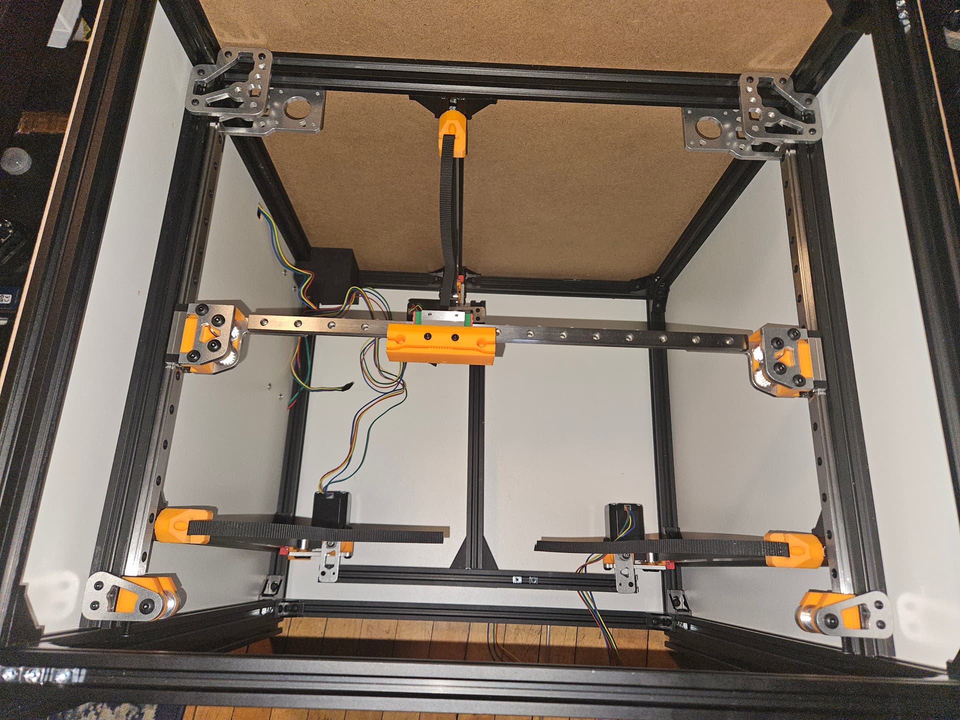
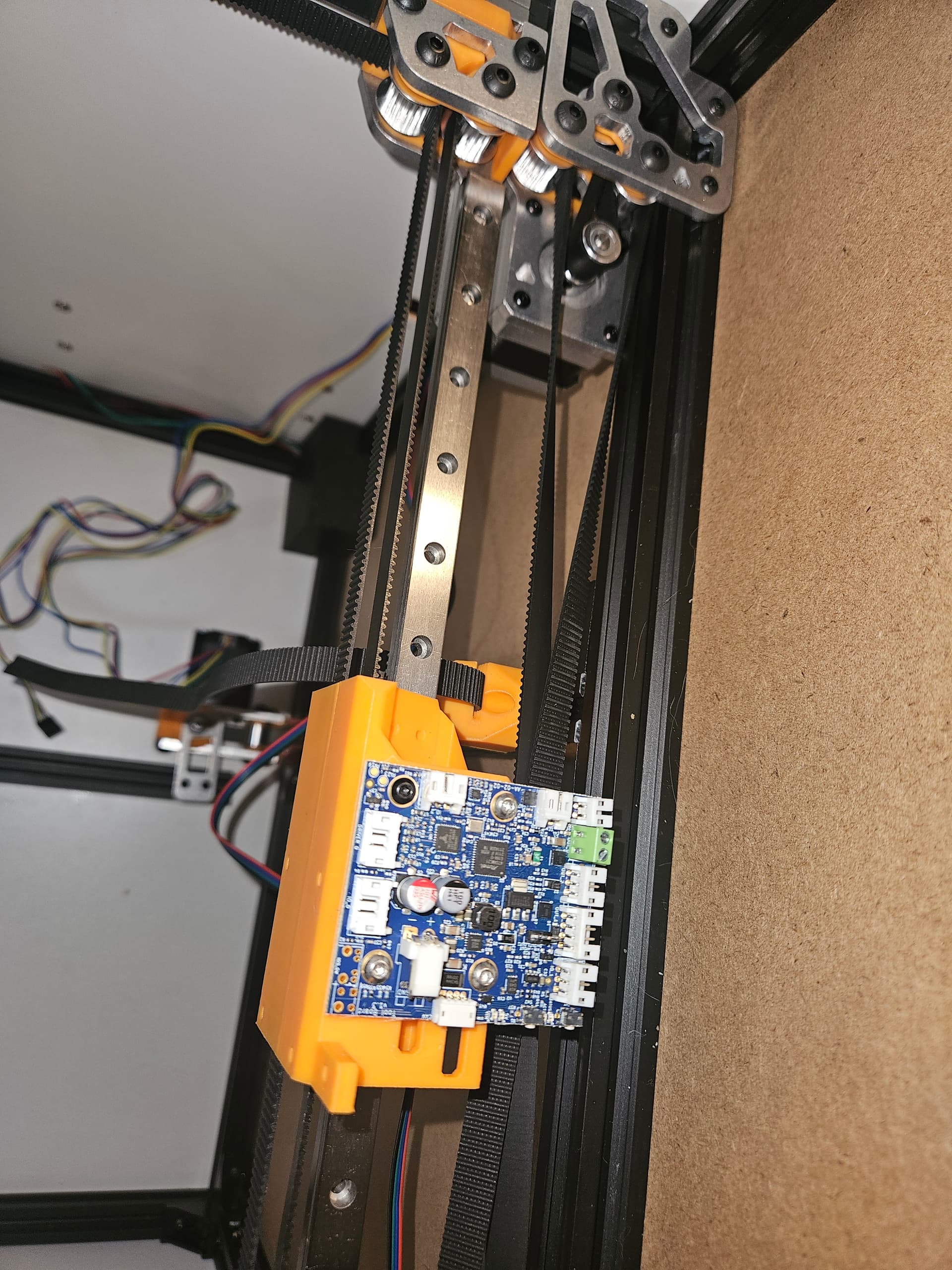
And, of course, wiring. Gonna try to keep things neat. Hopefully the 1LC tool board helps, with the CANbus, it’s 4 wires to the core, though I’m sure things will get spaghettified from the tool board to the extruder.
Edit: a couple more pieces, then Im done for today.
I am very interested to see what you think of it when it is done.
It seems so incredibly simple to me but ends up being so very complex. 8020 are “simple” but require so many screws. The metal is nice but I could simplify this going back to a v3 style CNC’d box and 3D printed parts with good properties like petcf. The adjustability of 8020 is a blessing and a curse. You have to take the time to get all the diagonals perfect….or just say screw it and use the software to skew your part to perfect. Slapping together a box with a lot less screws and parts then letting the software fix any locked in skew is probably what I would do if I did another build.
The toolmount is the most important but is overly complex. It works amazing as long as you don’t need to edit it.
I really want to make another printer to make some changes, but the off the shelf ones are just too dang inexpensive to spend the time on it.
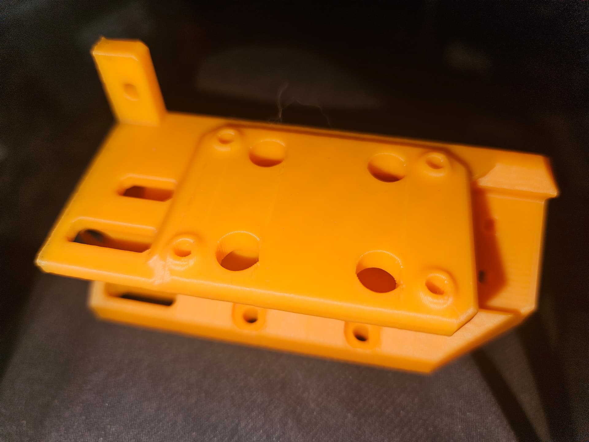
The editing from a mesh was a pain, but the result looks pretty good. Nothing important to the Hemera mounting was altered though, I only re-created the mount for the tool board. It was easier to start with the plain mount than the Canbus version, and I took a similar styling to yours.
Honestly though, after all this, Amazon notified me that the FlashForge A5M Pro is being discounted, and the only thing this offers over it is the 300mm build cube. (It’s worth it for that, as there are things I can’t do with the 220mm build plate.) Mind you I had the build volume with the Repeat, and with the aluminium X rail, it was quite good.
The 1LC tool board adds the accelerometer for input shaping, and with the Duet, I get to move to the more familiar (to me) RepRap Firmware from the Marlin I was on with the Repeat. The Repeat has been idle since the fan MOSFETs popped. I have another SKR Pro, so I could have changed it out, but with the v4 and the FlashForge, it never became a priority. I do have some things I want to print requiring the larger build plate, but have been collecting the filament colours they require.
I am quite happy with the v4, and if this works out, I will very likely change the v4 to use the same 1LC tool board, then I can do an “apples to apples” comparison with both being Duet based RRF builds.
The way we do it with the railcore is the panels are what set the extrusions square. Obviously your cnc router needs to cut square. At first everyone was using the extrusion corner cubes to make the frame square, until someone with good tooling actually measured them. They’re not actually square.
All I could find were the files for the H2 without the Canbus. I’m kind of used to editing from meshes, though, so it’s a pain, but doable in isolation.
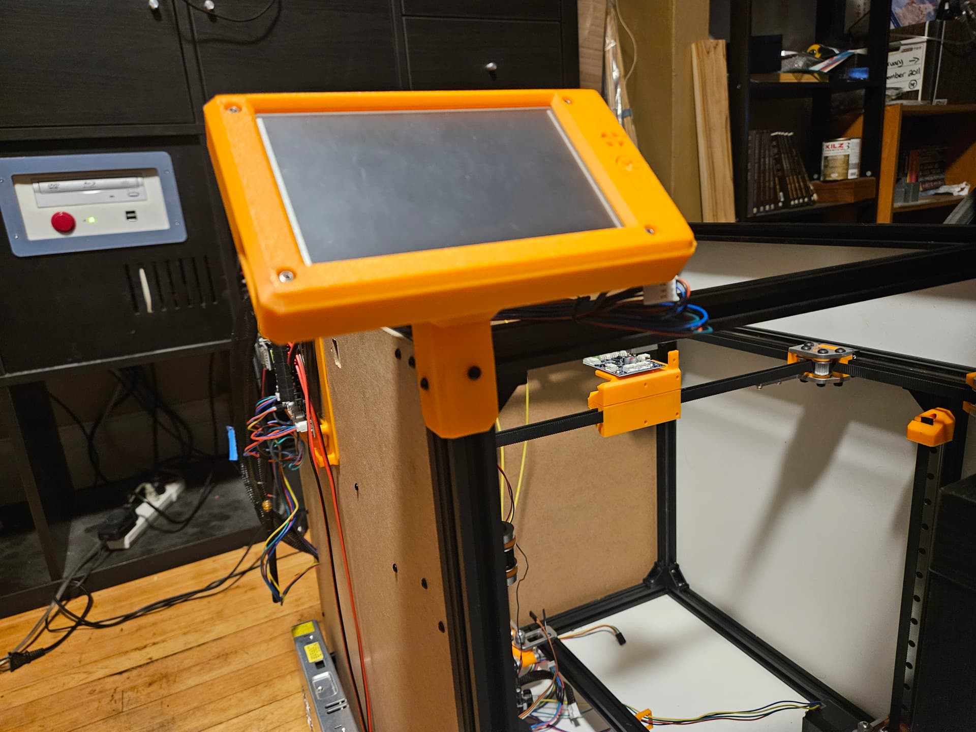
Thanks Ryan. I do have what I needed though, as you can see I have the 1LC toolboard mounted, the re-done parts in OnShape would alsp be good.
Fusion360 has a lot of really annoying bits to it, like forgetting the relative position of things when you alter parameters, but you need to sign dimensions for rectangular patterns, can’t just change which way you drag. Then something else changes, and positive 190mm becomes negative 190mm and your pattern is fubar.
I’d switch, but not sure where to jump for free/noncommercial. FreeCAD was pretty good at 0.18, though I never did figure out assemblies with it. I should perhaps give it another go at the current version, but if OnShape has a noncommercial license and more importantly, usable documents for things I actually want to make to start from, then that also would be good.
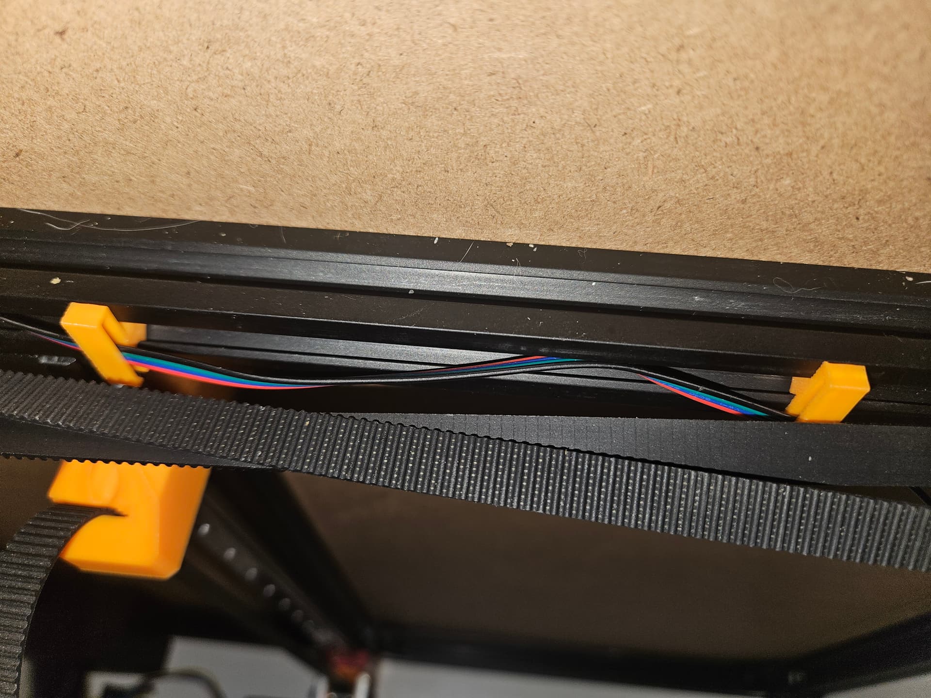
Started with a model for a twist-in nut, and added a 19.8mm by 5mm clip to hold.wires along the extrusion channel.
Edit: Wire Clip.zip (59.8 KB)
By the way, if wnyone wants to use it, here’s a .3MF of the wire clip. It’s not really spacious but in the location I’m using it, there isn’t much room. Good for motor/end-stop wires at least.
It is so horrible at that. I can specify a point on another feature and it loses it if there are no changes to that layer. By far the worst part of fusion and that for me makes it barely functional.
This was one of the reasons I changed mine to the Dragon Burner. Some work and editing and I have a mount that can hold any of the Chirpy Hotends and the AntHead with the LeafCutter mod I have almost finished.
I feel like the center can be something that allows adapter plates for any hotend you choose to adapt to it. It gives you options that way.
I need to mount the heated bed. The one I have was made for a CR10. It’s 310mm square, and has M4 mounting holes on a 240mm square
It is not totally clear where the front edge of the bed lives from the CAD that I have. Pictures swem to suggest that it is flush with the front edge of the extrusion, or even slightly back.
I.may end up scrapping the extrusion T mount and milling an MDF/melamine part to mount the bed.
Not sure if that will be helpful or not. But it shows where the bed lands for the CAD. Mine is built 25mm wider than the bed is so it does make it a touch wider, but same front/back.
The 1LC tool board is pretty cool, but a royal pain in the patootie in other ways. Most of thre connectors on it are JST PH, which are the little 2.0mm spaces ones. These are the same that some NEMA 17 motors have with the 6 pin connector. So I’ve been re-pinning the extruder motor, hotend and part cooling fans, thermistor, and the BLTouch. Oh boy.
The CANbus connextor is even better, JST ZH, so teeny tiny. They supply a pre-crimped pigtail for that at least
Power comes in via a beefy JST-VH, but while I have the crimp lugs for that, I don’t have the connector body for that. Maybe I have one somewhere else though.
It’s a very small footprint board, so I guess the smaller spacing of the PH connectors helps with footprint, but the 2.54mm spaced XH connectors are more useful in that it is easy to buy fans and other devices with appropriate connectors already installed. So it’s been a very unmotivating mass crimp session this past few days. I think I can at least power stuff up now though.
Most of the Hemera isn’t converted. I did the extruder motor connector, but haven’t done the hotend yet. I have a 5015 fan done, and thinking of changing out the 3030 fan, rather than redo the existing one. Still need to get the limit switches all done, too.
So progress, sure. Just slow. Maybe this time with wiring that doesn’t look like quite as much a mess… maybe.
Edit: oh yeah… made a mount for the PanelDue touchscreen…
gerk! Well, I bolted on the Hemera, cut the wires for the heater, since it is a screw terminal on the 1LC.
Just a bit too short. This is why cutting wires is a pain. The wires get caught on the braces holding the X rail in place. I’ll have to.figure out how to add ~1cm to them in order to have it clear. It may be easier to just use a different 24V heater cartridge. I may have more, I just have to check them for 12/24V with the multimeter. Maybe I’ll see if I have a better temp sensor, too. I ought to have a couple of PT1000 cartriges in 3mm case size around somewhere.
Because I have my electronics placed differently, I put the Y end stop switch on the top of the Y rail extrusion. It’s out of the way enough, so doesn’t look bad. Not as nice as tucked under, but not obtrusive, and way easier to get to the screws.