Joystick managed by Marlin

My implementation is on a Rambo, but this joystick solution should work fine with the SKR. Most of the discussion in this thread applies except board specific pin locations and pin callouts in the code. I only see one mention of SKR pins in this thread:

That’s a start.

2 Likes

Thanks Jeff, I think I’ll order one up and give it a try. :slight_smile:

1 Like

Hey Jamie,
debugging with this code did the trick!
I wirde everything correctly but my joystick has a range from 0 to 16k not form 5k to 10k… Plus the deadzone in the middle can be rather large, up to 1k or 1,5k…
So I changed it and no it works like charme!

@robertbu
That weird behaviour came from the rather big dead zone, I guess… So now it is no problem

This range would have had zero impact since the Arduino just sees 0 to 5V. Glad you figure out the dead zone. I’m also glad you did not burn out a pin. Rambo boards are more resilient than other control boards. I’m sure you would have burned out a pin on a Ramps board.

Hi Robert,
that’s what I thought, too.
Softwarewise, I have no idea what was going. I was just reading the values via debug and 0 to 16k is what I got. Anyways, it works and that is the important bit.

My SKR should be arriving this week - looking to add a joystick as well - is there any definitive info beyond this thread on what settings/connections need to be used? And do I understand correctly that this should work with both the lastest Marlin and V1 firmware builds?

It was enabled on the V1 Marlin firmware that I grabbed a month ago for a Rambo board. I think all I had to do was verify the pins called out in firmware matched my hardware connections. I did also tweak the deadzone and min/max values for my specific joystick, but the default values worked ok as is. That’s all I have in my notes on the subject.

I have a SKR pro on the way for a build that will occur sometime in 2021. If you don’t figure it out before me, I will be digging deeper in a few months and can post my findings.

1 Like

Are there enough extra pins to enable this all the time on the skr pro?

I’m not sure - here’s the best schematic I could find for the SKR:

It’s confusing that I can’t the pins @zwolf mentioned in his post. I see T0, T1, T2 and T3, but no TH0, TH1 or TB. Maybe H was added to denote a Header pin?

I can see no markings for analog or PWM like the Rambo has - noted in the post by @jamiek

Trying to understand all the board markings I found this reference - not crazy helpful but at least something of a guide:

In this photo @vicious1 posted for the SKR dual endstop setup, the Z is used for a touchplate but E0 port is not used, so maybe that Z is what @zwolf is referring to?

I’m pretty sure when they said TH, they meant thermistor, so T0, T1…

There are a bunch of pins on the extension ports. I would oeave the endstops alone because which ones might be free depends on the configuration.

I downloaded the data sheet for the processor used on the STK Pro V1.2 and checked capability of the pins on the extension ports. Besides 5v and ground pins, the remaining pins are all general purpose I/O capable and 5v tolerant. That means any of them should be capable of functioning as the joystick enable pin.

The joystick x,y,z potentiometer inputs requires analog input capability, preferably with a 5v reference.

Extension-1 pins PC1, PC4, PC5, PF7, PF8, PF9, PF10 are ADC pins that are 5v compliant.

Extension-2 does not have ADC pins.

Looking for a logical grouping of pins, I will probably use the 6 pins at the left end of Extension-1:

G, 5v, PC9(enable), PF8(x pot), PF9(y pot), PF10(z pot)

I don’t have my STK Pro in hand yet, so I can not verify this works.

3 Likes

I need to try this out.

The only other consideration is to make sure plugging it in backward won’t short the 5V to ground. So just don’t put the switch on the spots 180 from the power.

1 Like

If someone builds a 2x3 plug to use with the pins I proposed, plugging it in backwards will be ok with the pots centered, but cause shorts through the potentiometers in a few extreme joystick positions. Not sure this risk is a lot different than what I have on my Rambo board with individual pins needing to be in the correct spot. It could be made more error proof with a plug covering the full width of Expansion-1, but I doubt that would be a popular solution.

1 Like

Apologies, I never got around to rectifying the scheme. Thanks to Jamie’s help I was able to connect it properly, and I think it looks like this:

I share it in case it might be of help to anyone in the future.

Regards
Roger

2 Likes

Thanks @roger181078! I got my joystick delivered a few weeks back and at some point want to figure out how to get it working with an SKR 1.2 Pro.

1 Like

Yep “Dullard of the day award” goes to me.
Spend some time setting up the joystick wiring etc and the firmware by my computer upstairs with my spare Ramps 1.4 and motors, All Great!
Then went downstairs to my machine pulled apart my control box plugged it all in and the spend the next hour wondering why it wouldn’t work, checked rechecked my wiring couldn’t find anything wrong, so in frustration a great British tradition of a cup of tea was in order, whilst slurping upon my brew it suddenly occurred to me i hadn’t uploaded my joystick enabled firmware to my machine. DOOOH!! all works good now.
Please feel free to mock me, i likely deserve it. :laughing:

3 Likes

No worries, just invoke another British tradition: All’s well that ends well! :+1:

1 Like

Just be glad you didn’t spend an hour of debugging and rewiring to realize you had unplugged the power cable from both the machine AND the wall.

2 Likes

I am new to the forum and have recently completed my first build. I’m using a MKS SBase (because I already had one from my first 3d printer) and I managed to get through all of this info to get a Joystick and MKS TFT 35 display setup and working in a single unit based on this one form the thread:

I purchased this joystick:

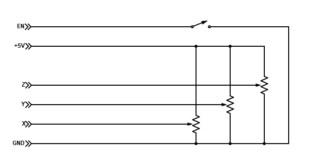
Note on this Joystick, the top turns left and right for the Z axis and the wires coming out of it are not what you expect, the two blue wires are for the button on top of the stick, the black is the Z signal cable and white/red are the +/- so the black wire goes to the Z pin, red goes to say ground and white goes to 5v.

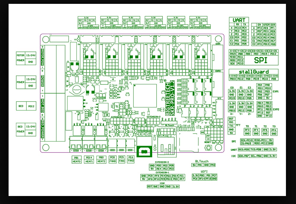
I had some trouble getting this all working so I figured I would provide the details here in case it helps someone else in the future. There were limited available pins on the SBase that I could get to work, only 1.30 and 1.31 seemed to work for the x y z signals on the EXP1 and EXP2 ports and none on the J7 or J8 ports. In the end I compared the SKR pins mentioned in this thread somewhere and found the thermistor signal pins on the SBase work for the x y z signals as well. After that I found other info online that pointed me to P1.23 on the J8 connector that is the only available PWN capable pin that apparently is needed for the Joystick Enable pin as far as I understand. Here is my final config in Marlin:

#define JOY_X_PIN P0_23 // MKS SBase TH1+ (Heated Bed)
#define JOY_Y_PIN P0_24 // MKS SBase TH2+ (Extruder1)
#define JOY_Z_PIN P0_25 // MKS SBase TH3+ (Extruder2)
#define JOY_EN_PIN P1_23 // MKS SBase J8 Pin 3

That all worked fine and I found the following values for the dead zones on this joystick:

#define JOY_X_LIMITS { 0, 3235-100, 3235+100, 4095 }
#define JOY_Y_LIMITS { 0, 3110-100, 3110+100, 4095 } // min, deadzone start, deadzone end, max
#define JOY_Z_LIMITS { 0, 3068-100, 3068+100, 4095 }

And for those who may be confused by the deadzone numbers, when joystick debug is enabled you can run M119 to list the current joystick x y z and en values along with the endstop values. With the joystick in the default position the x y z readings will be at specific values that seem to float a bit. In the code above the first number “Min” is the lowest number you see when moving an axis as far as it will go one direction and the last number “Max” is the highest value in the opposite direction. That should be clear but what I didn’t realize was the the resting value would be a number somewhere in between and would move around a bit. I rebooted several times and ran M119 to get a range of values and then picked the average for each axis without moving the joystick around. This gave me the base value for each axis and then I added that number in to the code above for each axis with the first number being the average value minus 100 and the second being the average value plus 100 as shown above. Example: #define JOY_X_LIMITS { “min”, “average resting”-100, average resting+100, “max” }

Hope this helps others with the SBase or just in general trying to set this up and thanks to the creator of this code, it’s awesome to have this working and to see it integrated into Marlin, congrats!

Here are some modified diagrams based on the previous forum posts adjusted to my setup and the layouts of the MKS SBase for reference. I left out the LED and just went for an enable pin to ground on a single throw switch so just on/off:

1

7 Likes

Read this whole thread and its great! However I may have missed something.

Joystick has arrived and case is printing.

Just one lingering question about the wiring of the + and gnd to the pots. It seems to me that as the joystick is pushed in a positive direction to cause positive movement, the wiper in the pot should move toward the +5v terminal to produce a higher voltage at the center terminal and thus a higher number to the code and result in a positive movement.

This is going to a SKRv1.3 board. Plan to used the thermistor pins for x,y and. Also there is a “servo” pin intended for a bl touch that I will use for the enable switch.