I’m going to be honest, I have already lost much of what I learned doing this but assuming you follow my post it should all work fine. Using the joystick debug and M119 will tell you everything you need to know about the values to enter, that much I do remember. It’s still working great to this day and I haven’t modified anything from what I posted. If you have trouble I can take my joystick apart and take pictures though it’s a bit messy inside if I remember correctly.
It might not be obvious which direction will produce less resistance to the left or right contact, and for the Z axis it’s even less clear if clockwise means signal (black) moves toward red voltage or toward white voltage.
It’s possible to test each one individually and wire accordingly so higher voltage corresponds to movement in the positive direction. It’s definitely doable but it’s easy to get backwards.
The firmware has an option to reverse the polarity so you can test it and reverse polarity if necessary. It’s an extra step but if you soldered one or more axes backwards, it’s a lot easier to reverse the polarity and recompile, rather than rewire.
Ahhh… you’ve already thought of that and did it in the code.
Well done! And thanks for a great job!
Ok, its all working on my SKR V1.3 board, video later.
Thanks to jamie and voodoofivetwo!
Just looking at the possibility of adding this to my SKR Pro V1.2 board when I get my MPCNC finished.
On checking schematics to find some spare pins Extension 1 would seem to have everything needed. It exposes 5V and GND as well as PF 8, 9 10 which connect to ADC3_IN6, 7, 8 if I am reading the schematic right.
Would anybody be able to confirm this? Or if you have already fit a joystick to the SKR PRO could you say what pins you used?
Thanks.
Tomorrow I’m going to try and wire up my skr pro to the joystick.
It looks like the expansion 1 header has plenty of inputs so ill try and use that. ill post my findings.
@gforce2010 - Reporting back on SKR PRO 1.2: IT WORKS.
There are some gotchas so ill try and give some basic steps:
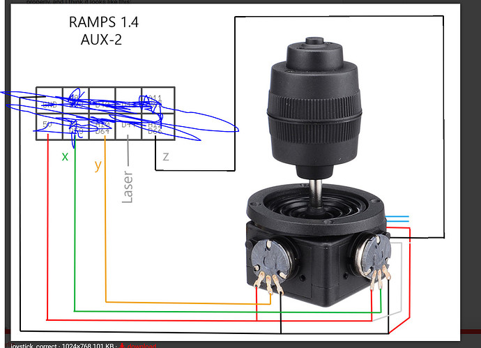
- The diagram I used for wiring MY joystick is as follows:
X: PF8
Y: PF10
Z: PF9
EN: PC4
HERES THE TRICK: You must use 3.3v output on the board near the endstop switches rather than using the 5v as much of this post describes.
configuration_adv.h:
#define JOYSTICK
#if ENABLED(JOYSTICK)
#define JOY_X_PIN PF8 // RAMPS: Suggested pin A5 on AUX2
#define JOY_Y_PIN PF10 // RAMPS: Suggested pin A10 on AUX2
#define JOY_Z_PIN PF9 // RAMPS: Suggested pin A12 on AUX2
#define JOY_EN_PIN PC4 // RAMPS: Suggested pin D44 on AUX2
//#define INVERT_JOY_X // Enable if X direction is reversed
//#define INVERT_JOY_Y // Enable if Y direction is reversed
//#define INVERT_JOY_Z // Enable if Z direction is reversed
// Use M119 with JOYSTICK_DEBUG to find reasonable values after connecting:
#define JOY_X_LIMITS { 0, 8000-400, 8190+400, 16384 } // min, deadzone start, deadzone end, max
#define JOY_Y_LIMITS { 0, 8000-400, 8250+400, 16384 }
#define JOY_Z_LIMITS { 0, 8000-400, 8080+400, 16384 }
#define JOYSTICK_DEBUG
#endif
Tuning the Joystick:
Once i got it all wired and plugged in. I attempted to “zero” the pots on the joystick as they are adjustable. I attempted to get the resting value to 8000 by unscrewing the adjuster and moving the pot manually. You can do this for Xand Y, but my joystick Z wasnt adjustable… luckily it was pretty close.
Once tuned, I pushed each axis to each side to get max and min. For me it was the whole darn range — thats ok.
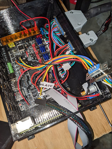
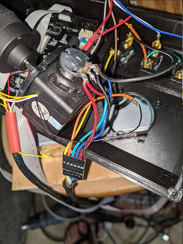
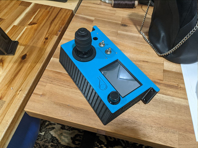
Heres some pics:
What great timing you have, I was literally soldering up my joystick when the notification came through.
Thanks for the tips, my Joystick is now installed and working great.
Do you have a link to the STL for that control box with the Joystick?
I made it, and here it is champ
https://www.prusaprinters.org/prints/77250-tft35-e3-case-joystick-switches
I kinda wished i had gone with something like this:
would allow for me to guarantee that i only move one axis at a time.
I tried one of those and they have really poor resolution. It was extremely hard to get small movements, which is sorta the point of a joystick over simple jog buttons. Maybe you could glue a long stick onto it to get finer control. I didn’t try that hard before upgrading to the fancier joystick.
Also, it is possible to increase your dead zone so you don’t accidentally move one of the other axes. It’s a matter of personal preference if you prefer them touchy or if you want it to require more movement to respond.
yea - increasing deadzone is what i changed to today. youre right. exactly the functionality i wanted. also the endstops work great with the joystick as well. great job @jamiek. appreciate your work!
It’s Soooooooo Cool!
Can I get this on the SKR 2???
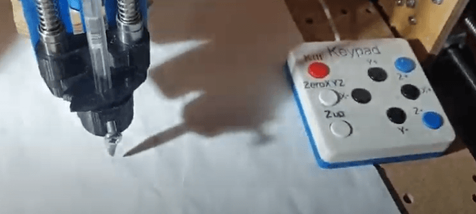
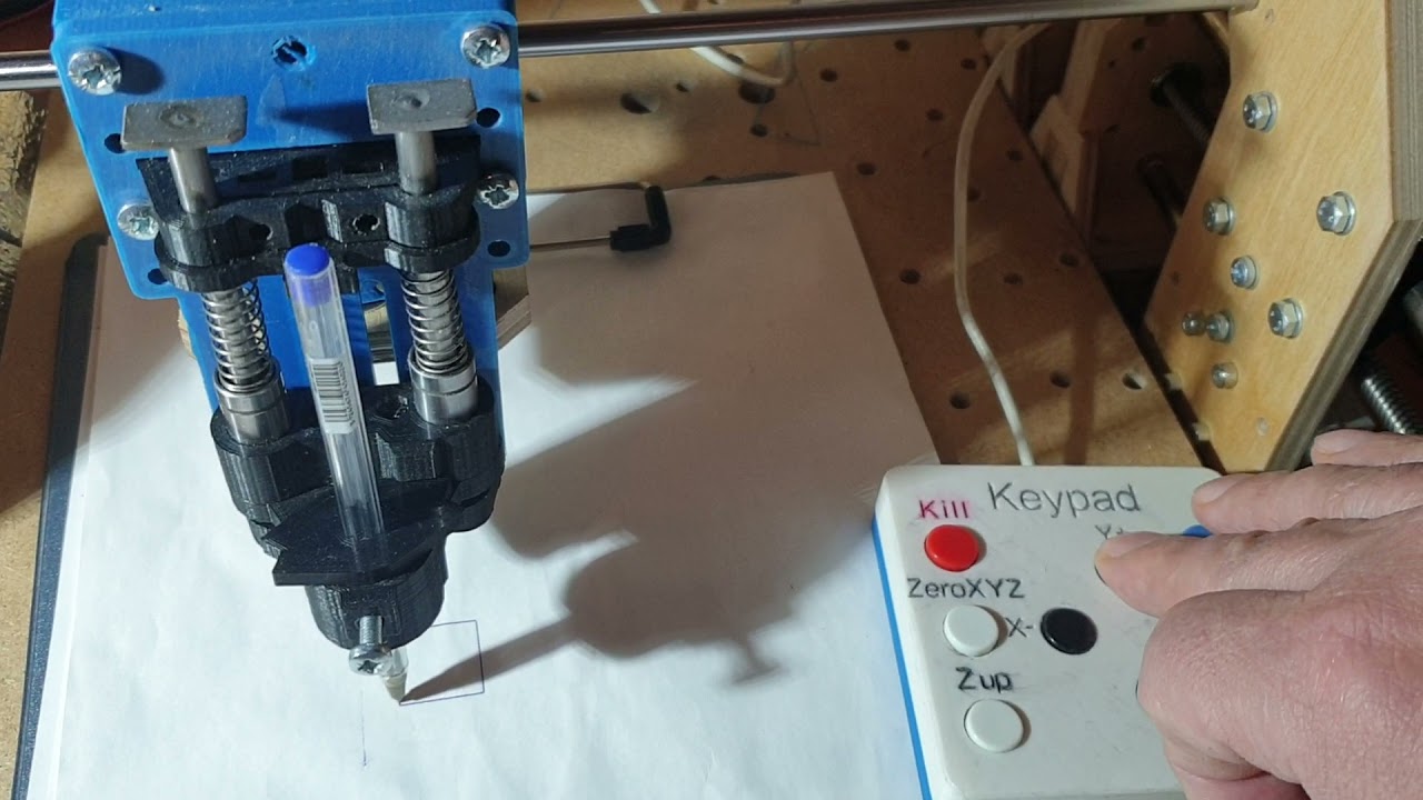
Is that with an arduino inside? A few have made external controllers like that before. Those have the advantage that you can program the buttons to do anything.
So did you have to modify Marlin, or is there an existing Marlin interface that maps inputs to buttons?
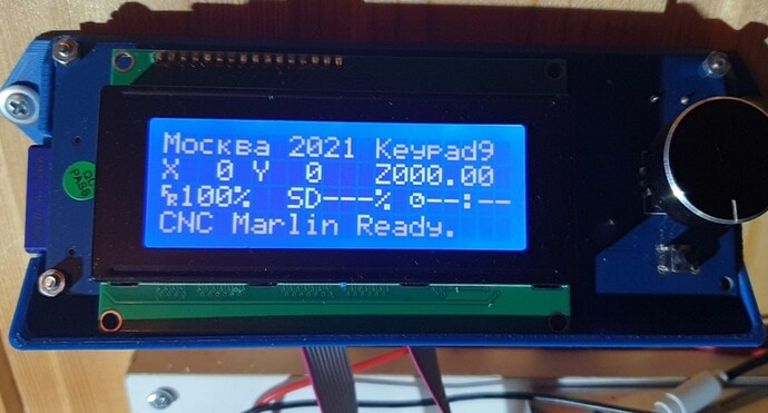
I can’t insert a youtube link to the video, but it can be found by searching for “Keypad9”
Many small changes have been made to Marlin for the display and one program in the Loop.
It’s very simple, but it works. Polling of analog inputs and simple programs like:
while(ReadSensor1(5,CntRead)) {
// Serial.println("Кнопка 9 ");
digitalWrite(Z_DIR_PIN,HIGH);
digitalWrite(Z_ENABLE_PIN,LOW);
for (int m = 0; m < 16; m++) {
digitalWrite(Z_STEP_PIN, HIGH);
delayMicroseconds(3);
digitalWrite(Z_STEP_PIN, LOW);
delayMicroseconds(100);}
// delay (1);
if (ReadSensor0(3,CntReadS)) {
// Serial.println("Кнопка 3 ");
char z_com[12];
sprintf_P(z_com, PSTR(“G01 Z%i F500”),z_up);
SERIAL_ECHOPGM("Button 3: ");
enquecommand(z_com);
// delay (1);
}
