The GridBot UI is highly editable. Code contributions more than welcome. I don’t like the DC/DC converter options out there. I’m trying to convince my son to develop a better power supply with 24 and 5v rails.
On the back panel, I feel ya. Looks great as long as you don’t take it off. It’s one of the things I’m redesigning in GridBot v2.5 or 3.0 — we’ll see which comes first Also working on a full enclosure for screen + PI. My son also has a lot of opinions on this.
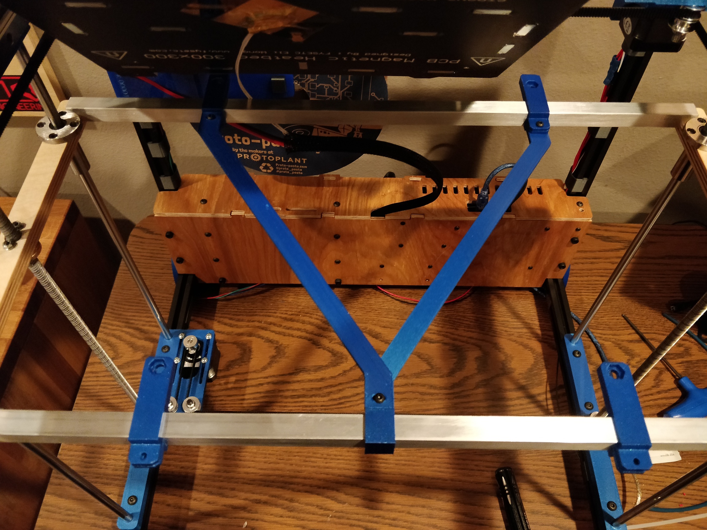
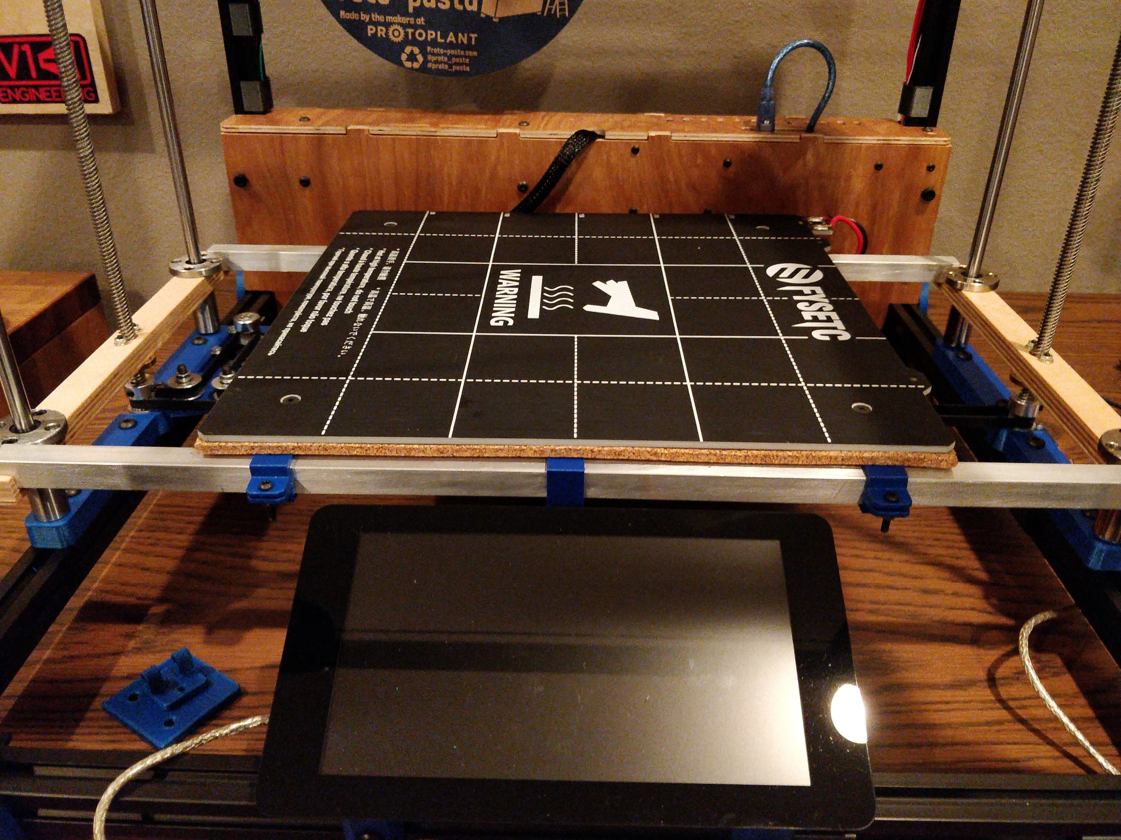
Just an FYI, this is a PCB bed, with a heater etched on the top, and the bottom has cutouts for magnets, which they epoxied in. On top is a spring steel sheet, with a PEI sticker on it. Underneath is a piece of cork. The whole thing is mounted rigidly (no adjustments) to the two aluminum C channels.
I’m not sure which part is bulging, but since it’s in the middle, I think it is the PCB. I am guessing you’re asking because a piece of aluminum will expand with temperature, and that would even out over time, which would make it flatter.
I don’t like the one I put in there either. I inteded to make a cheap bench power supply with it, and it defaults to having the output off, so I have to keep lifting the printer to push the power button.
I leave my beds floating on three thumb screws. The screws are positioned in such a way that they “capture” the cork, thus no sliding around. But also, the bed isn’t mechanically bound against expansion and contraction.
I could try to loosen the screws and see if that helps. I need to do some comparisons. I’m interested to see if it is a problem day-to-day, or even right after warming up vs. after a few minutes or an hour. The bulge doesn’t really bother me, as long as it is consistent. I can definitely loosen these nuts that hold it on to give it some slack.
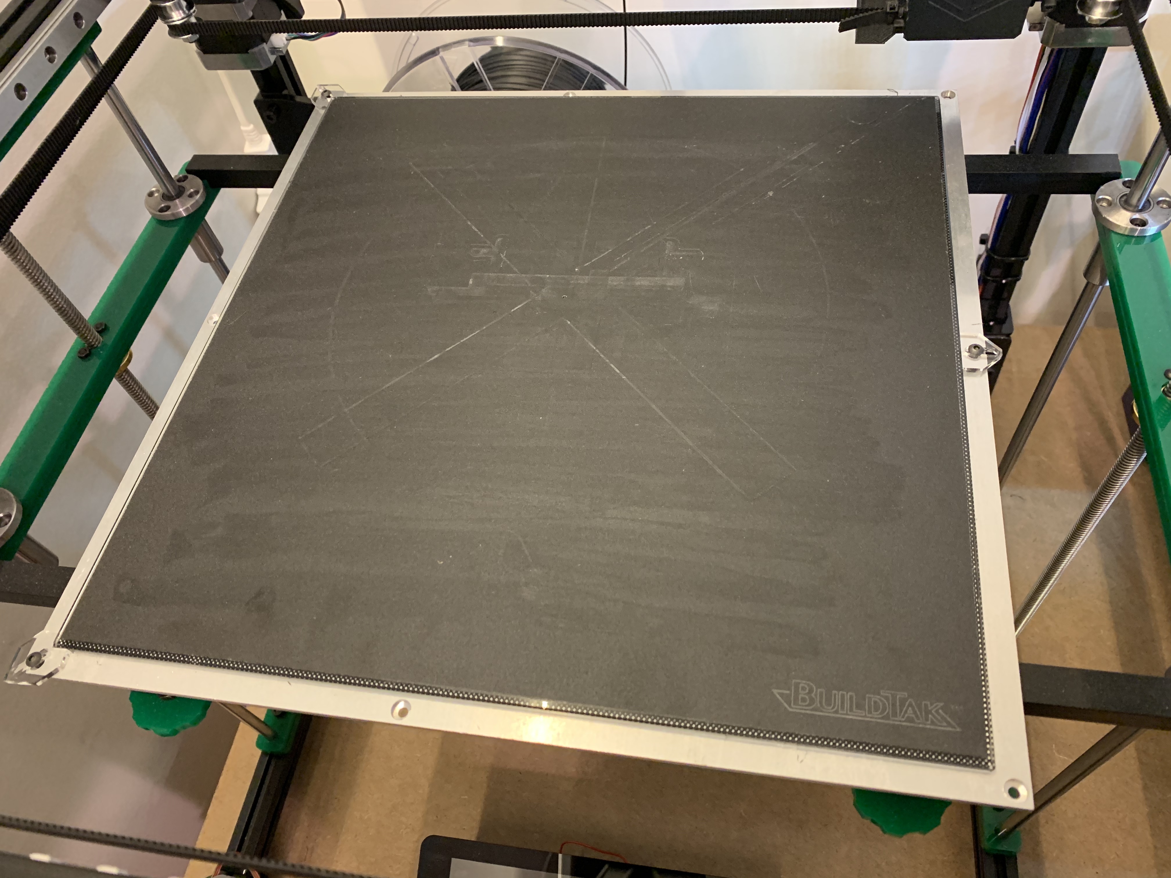
I’m getting to the point where I’m happy enough with the bed levelling. I certainly think I could print a big object, although it might have a tiny foot on it right now. I am printing a big spider web, and then measuring the thickness with my calipers, and it is between 0.1mm and 0.18, when it should be 0.2mm. So I should be able to tune that out with M851.
I don’t know if I’ll ever print this high. But it’s nice to know it’s clear. I also loosened 3 of the bolts holding the bed down. So one is tight, nearest the corner I home. The other three are loose. I am not seeing a difference in the bed level though. NBD.
i see. your heated bed is smaller than the ones I sourced which are 330x330. so on my printers, the bed sits on the thumb screws just outside the cork.
Does anyone know the current requirements of the signal from the controller to this mosfet board? I currently have it attached to the builtin bed connection, but I’d like to have this case fan turn off when the motors are disabled. So I am thinking of moving this mosfet input to a spare pin, and using the Bed pin for the case fan. But all I see are people connecting it to high voltage, high current capable outputs. I am a little worried it will draw 150mA or something strange, and then toast the microcontroller on the SKR.
I suppose I could just test it on a 5V supply and see.
I tested it, and in my testing it needs at least 6.5V to trigger . When it does trigger, it doesn’t sink any current. I’m not sure if I am just misremembering how these mosfets work, or if there are other components on here that are keeping it from triggering at lower voltages. Bummer.
I could probably get away with using the same fan output for the extruder fan and the case fan. It would be nice to be able to configure the software to turn it on if either Extruder temp > 50C or any motor drivers are enabled. That would make it quieter in here when I’m working and not printing, but still turn these fans on when I need them…
Are you talking about a case fan for the electronics?
If so, then I think I’d just run the case fan off of the same control as the extruder. If the extruder is hot, then chances are the stepper drivers are producing heat too. Not too often would the stepper motors be producing heat on a 3d printer when the hot end isn’t hot.
Alternatively, you could do like I did… I have an enclosure fan on my 3d printer. I run it off of an Arduino Beetle controller with it’s own temp probe. It turns on the enclosure fan based on the temperature inside the enclosure. At the time, I did this so that I could use a switch to change the set point depending on if I was printing ABS or PLA. These days, I pretty much only print PLA, so the fan is always on. I should really just hook that up to the 12V on the power supply now that I think about it.
Yeah. A case fan for the electronics. I thought about just connecting it to the extruder fan. I wouldn’t be surprised if it works fine without even having a case fan. But my worry is that when I’m doing stuff like probing the bed, it will overheat. They are TMC, so the worst outcome is they would reduce their current until they were power cycled. I think I’m going to try that, because it is a 2 minute fix.
 Also working on a full enclosure for screen + PI. My son also has a lot of opinions on this.
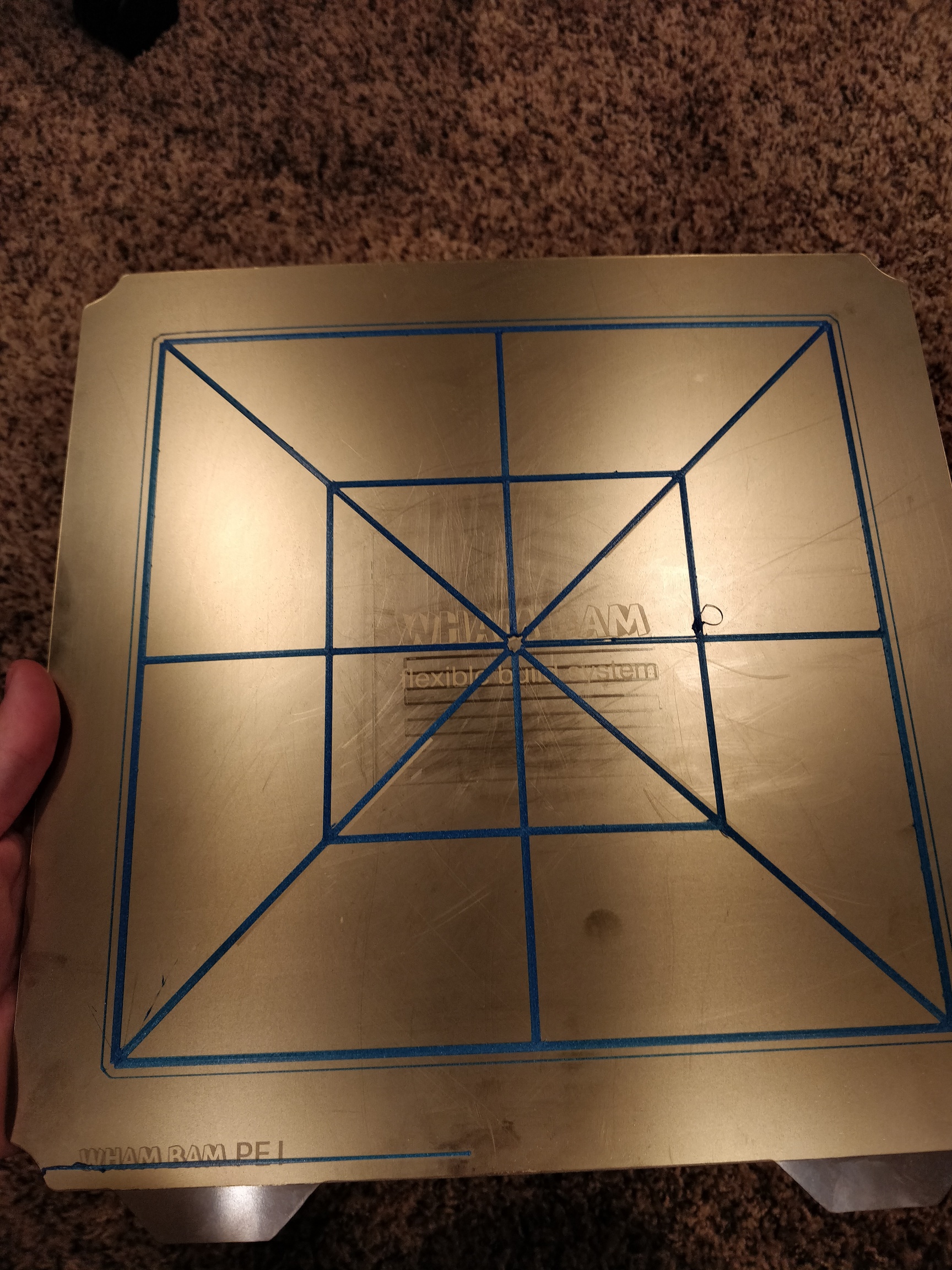
 . When it does trigger, it doesn’t sink any current. I’m not sure if I am just misremembering how these mosfets work, or if there are other components on here that are keeping it from triggering at lower voltages. Bummer.