These should work:
1 Like
were these too large to print?
Yep. The bed I have originally had 220x220mm, but it has shrunk a bunch in my latest extruder swap. I was thinking about fiddling with it until I could get it back near full size, but I will have a 300mmx300mm bed soon.
I will also have to carve the electronics case with the cnc. That will be 1/4" ply, probably.
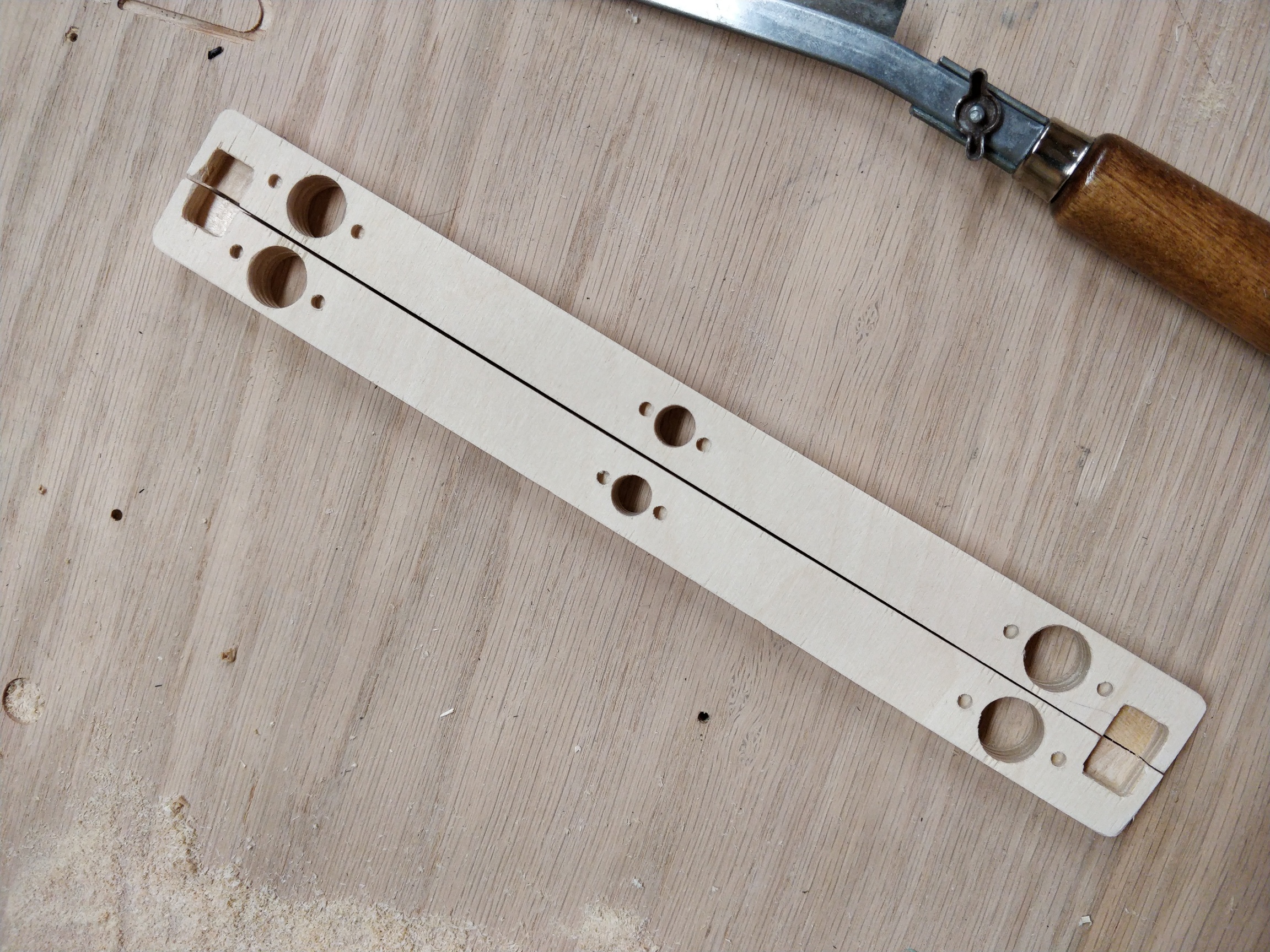
I lost a few chips while test fitting. I should have oriented them with the veneer grain. I’m in the process of sealing them now.
1 Like
you can also cnc acrylic. i do that with the same sheets i laser cut.
I could. I’m not sure what the benefit would be. This seems very rigid. The chips will be covered by the flanges.
possibly rigidity. how does the birch compare?
1 Like
Should be more rigid than acrylic.
1 Like
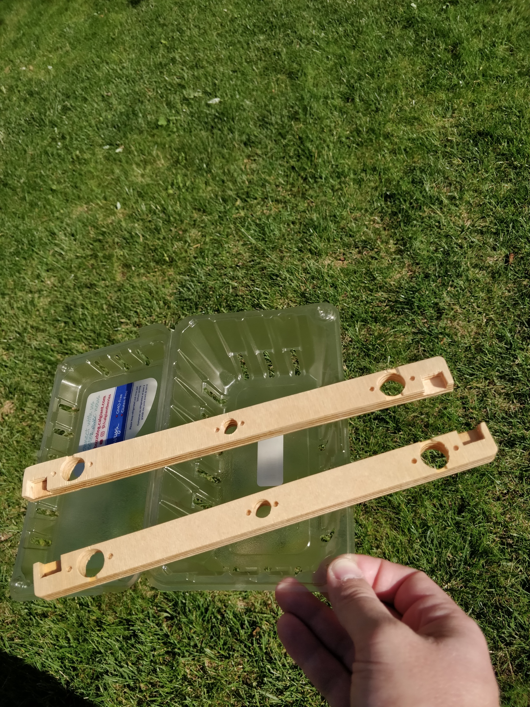
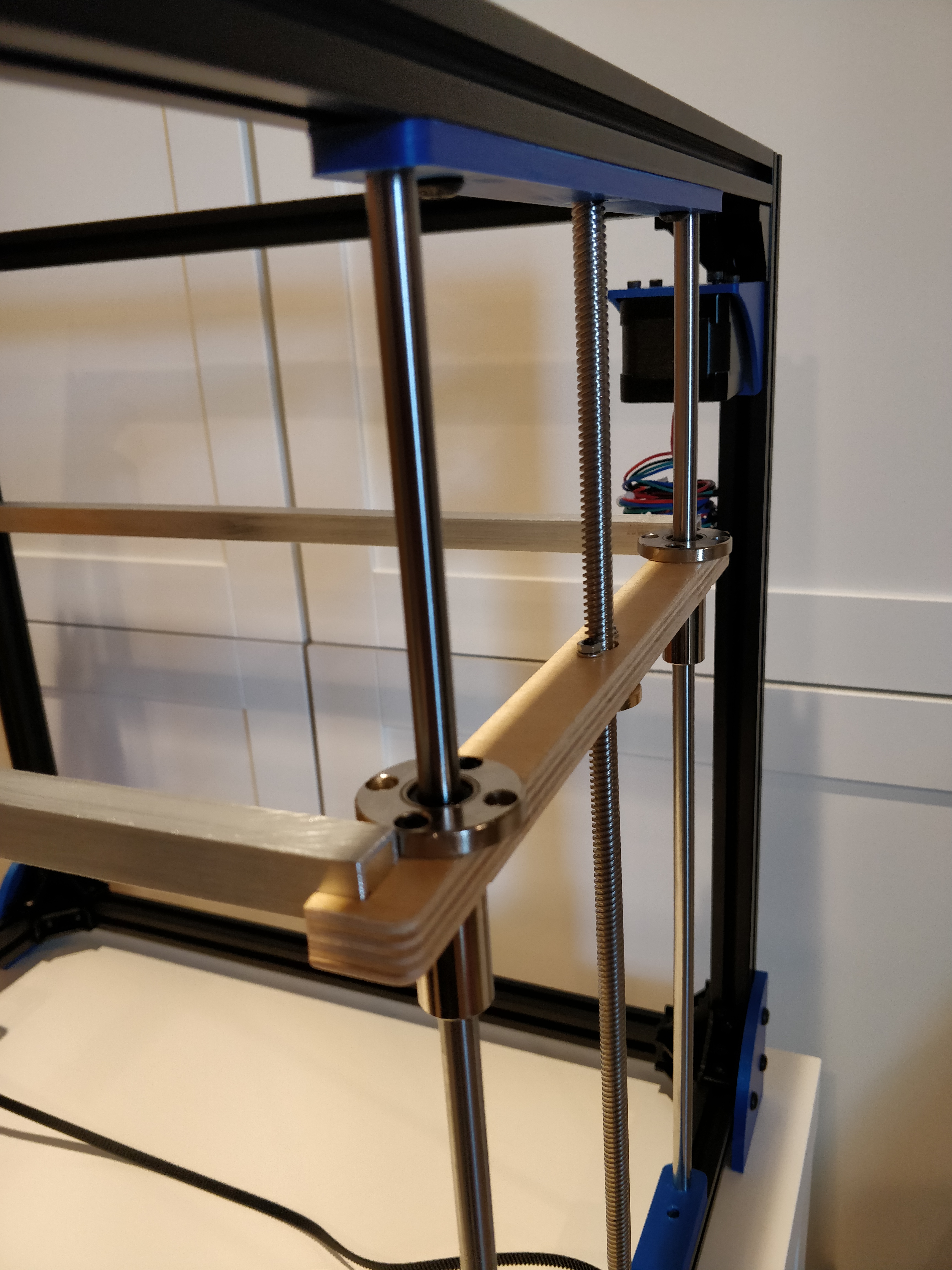
I’m not sure what the critical functions of this are. It is pretty solid. It is 1/2" thick. But I could definitely break it if I sat on it. That’s about as close as I can describe it :). The interface with the 1/2" aluminum C channel is pretty good, and the whole thing will stay together and generally keep its shape. The fit around the bearings and the leadscrew nut are tight, so I can imagine it binding if it isn’t perfect.
But what is it trying to do anyway?
- It needs to move as close to up and down as possible, without side to side motion. So as long as it doesn’t bind, the bearings should handle that.
- It has to smoothly move up and down.
- It has to sit down all the way (I am a little worried I will bump the C channel and it will lift up a tad, and that would cause headaches).
I may just have to create some glue solution once I have it all fit together. But I will wait to see what problems I’ve made for myself first :).
for this part, it just holds the weight of the bed. i’ve seen printed plastic bow slightly. i agree the wood should be sufficient.
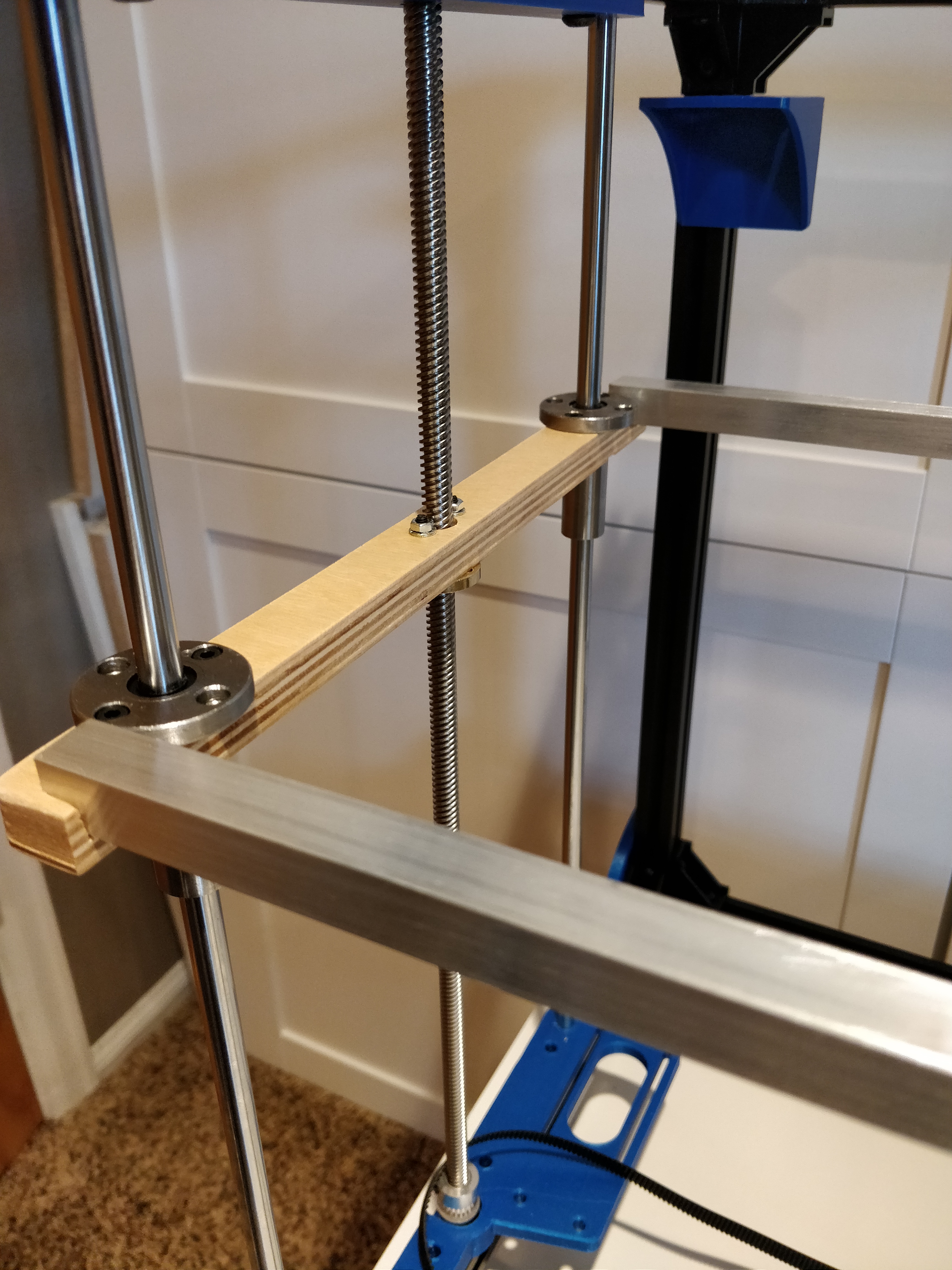
Ah, so it needs to not bend between the nut and the C channel attachment. I think this will do that fine. I am more worried about the slop in the aluminum to wood.
we will have to talk about z leveling and issues you may experience. all easily solved with the right technique. i have found that if the z binds after leveling to the bottom that it is sometimes caused by over-tightening the M3 bolts that go through the lead screw flange. because the bore hole through your wood in this case might not be perfectly vertical, or the wood could be compressed enough that the flange becomes slightly out of line with the desired z motion.
I have had similar issues with my other machines. I think I may make the nut hole bigger, and use just one screw. They can bind easily. I haven’t tried it yet.
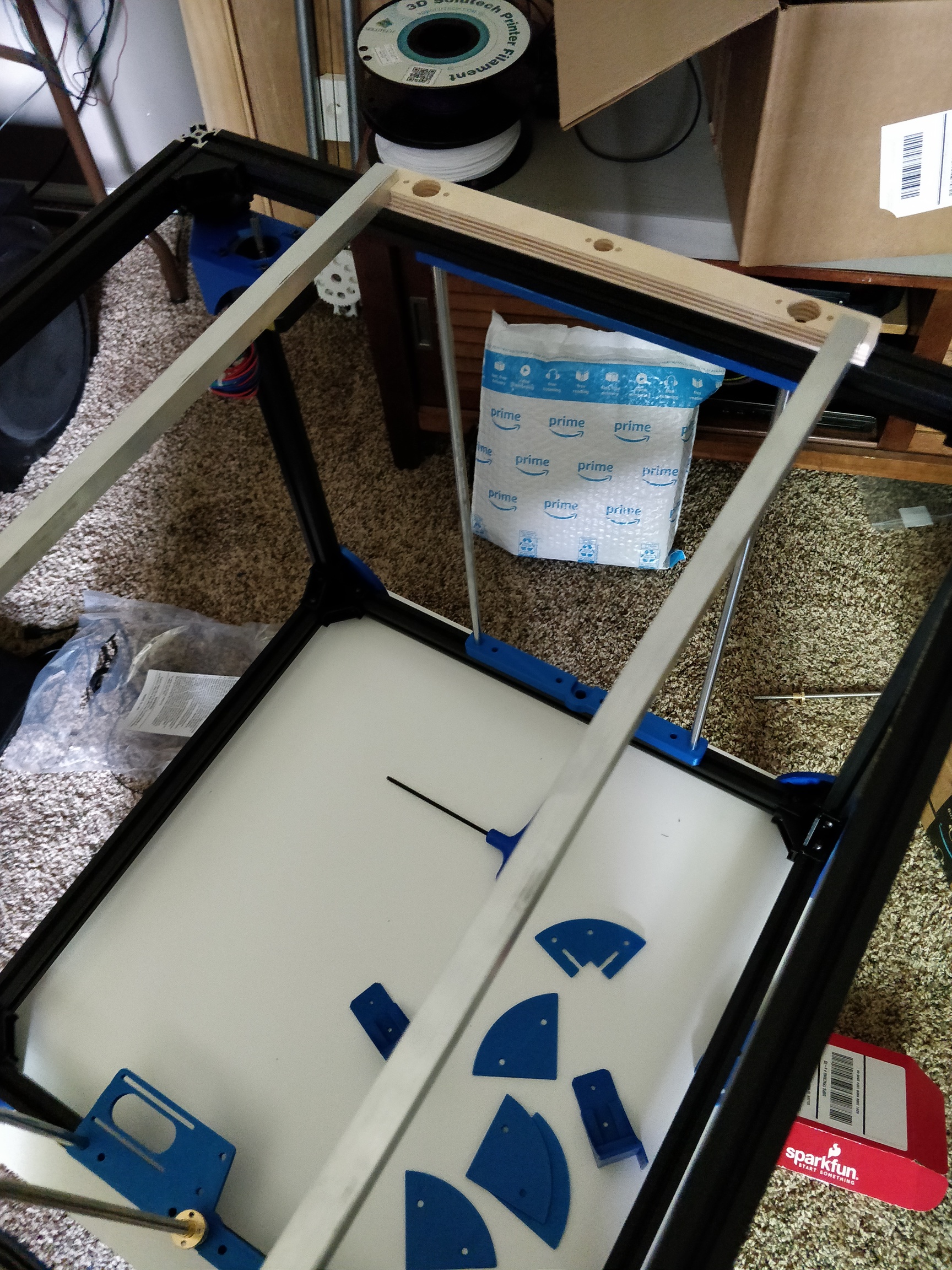
I don’t know how, but this step turned out great!
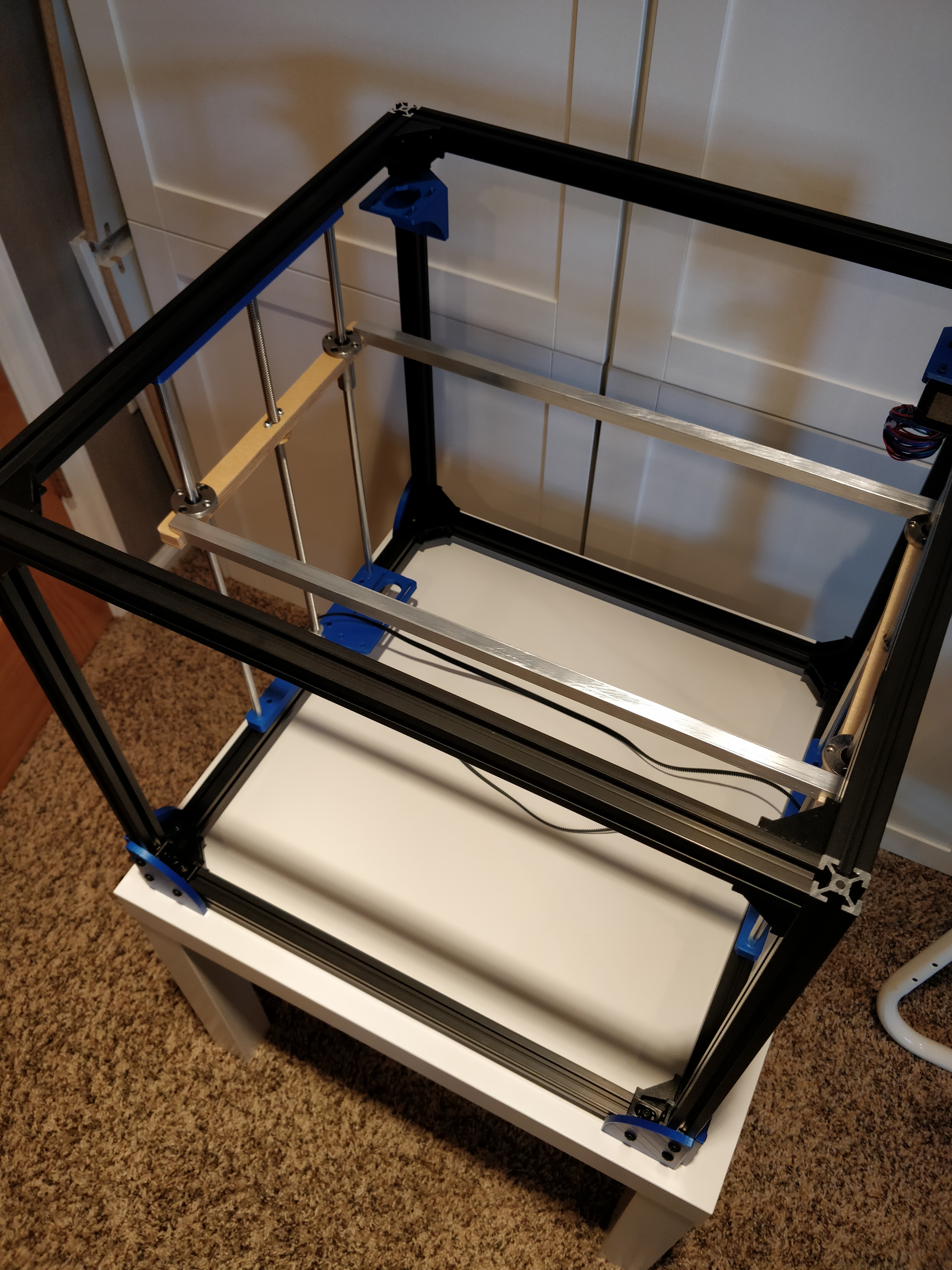
I was really worried when I was assembling it that the holes would be in the wrong place, or they would be out of alignment enough to have a bunch of slop. But when I installed those cross members, it just became SOLID.
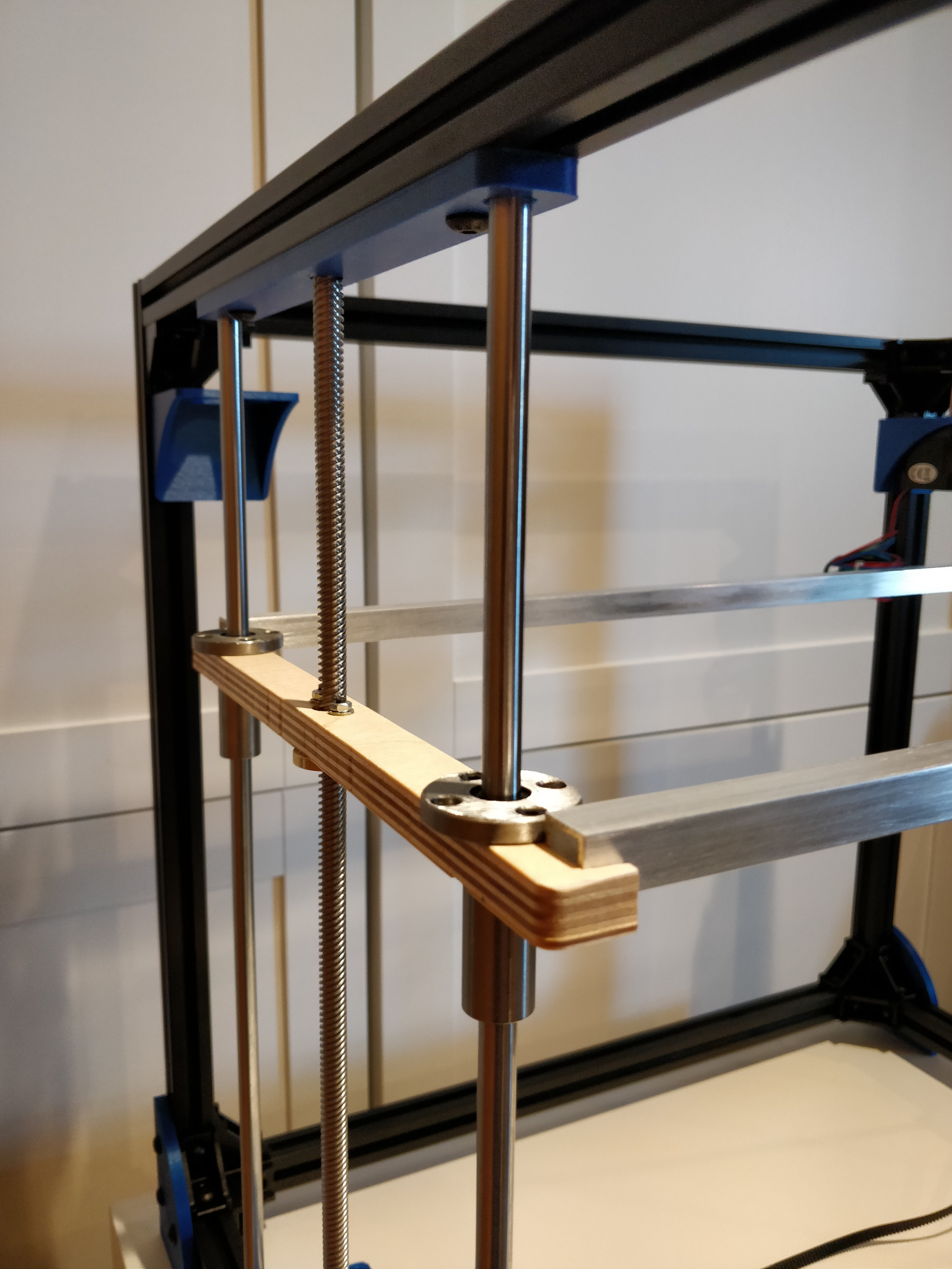
There is a tiny amount of binding on one leadscrew, on one end, in the top 50mm or so. I’m not sure how high it will need to reach, but this is without any lubrication, and the screws are tight. Once I get more in place, I will try removing one of the screws, or loosening the nut. I want to go back and replace the nuts with nylock nuts anyway. I am also missing the bolts that hold the bottom in place, so there may be some more binding once I have to pick a spot for those.
Now that I’ve seen it and touched it, I think the major challenge of this is the tipping of the bed front to back. The flanged bearings are trying their hardest to keep that from happening, but they have some gap (however small) and it gets amplified at that angle. I was worried about that a bit when I was assembling this. When I finally got it all together, I think it won’t be a problem immediately. I had to push reasonably hard (500g?) to get it to move a full mm. The good news is, it went back to zero when I let go, so I suppose it will be fine while printing, especially with a BLtouch. Short of another LM8UU bearing lower or higher, I don’t see a good way to make it stiffer.
I’m really close to having all my parts. The bolts were supposed to be here Saturday, and they are a no-show so far. They are the limit ATM.
4 Likes
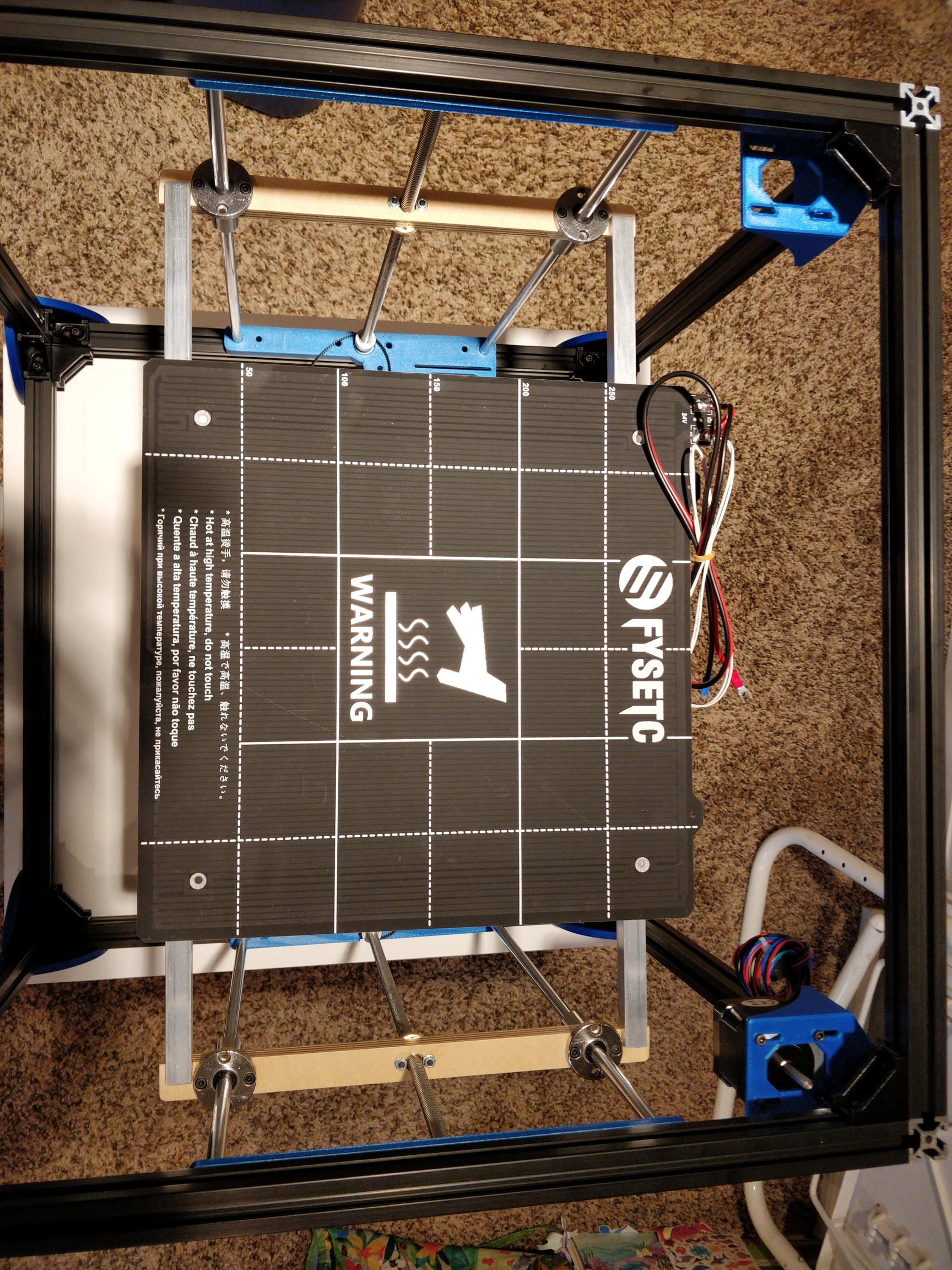
The heated bed I bought has mounting holes in a centered pattern 240mmx240mm. The holes almost align with the C channel. The mounts that are in the CAD work fine with this c channel. So I think I am going to slightly adjust them to hold these 4 holes. I’ll have to offset them to one side of the channel, and make one longer to account for the 240mm.
I am going to just mount them firmly, without the leveler feet. I am banking I will get close enough for the mesh level to fix any offset. If not, then I can get the leveller feet involved again.
You’d have to print everything on a raft if you want square parts that way.
The bed leveling is to fix errors <1mm over an area of 300mm. I don’t think I will notice if it isn’t square.
It will all depend on how close I can get it by just bolting it down. My 200mm printer is bolted down, and the measurements are all within 0.4mm.
1 Like
I bolted down the bed on my TAZ 5. It’s a 300x300 bed. It worked even with a 1.2 mm height diff from left to right. But I shimmed one side anyway to get it closer to a .4 mm diff. That part works. But the X Y accuracy isn’t as good as I want. It is just too big and those 10 mm rods flex too much at those lengths.
once it’s all bolted together and secured, z should be solid with very little flex even under weight. the two cross bars under the bed that hold the level screws help to reinforce this even more, and you don’t have them on yet.
1 Like
The design looks very nice! And it’s fun to follow the build.
Since the designer is also reading this, I have a few questions. Why doesn’t the Z axis use 4 lead screws (one in each corner)? With the belt and pulley system you could still drive all 4 with a single stepper, right?
Also, on a scale of 0 (standard ground rods with linear bearings) to 100 (expensive linear rails like genuine hiwin), how well do the cheaper linear rails perform?