I have upgraded to the new Jackpot3 controller from the RAMPS 1.4 controller setup. I was having too many problems with the RAMPS 1.4 so figured I would get the latest and greatest. I ordered the JP3 from the V1 site and installed it yesterday. I have it connected through FluidNC WIFI and I started looking at bumping axes to see what was working and what was not.
I had connected the steppers per the drawing so X-Z on their drivers and then X1 on A and Y1 on B. Also connected the limit switches for future use but have not configured or connected those on the CNC yet.
When I started bumping axes, only X and Y motors moved. When I bumped Z, X1 also moved with Z. That got me thinking maybe the default JP3 config is expecting to have the steppers in series per original design vs. the dual setup I put in put in place.
I went into the FluidNC WebInstall and saw that the axes recognized are X Y and Z and A, B, C are all disabled.
Now I am a bit confused since the X1(A) moves with Z. I took the config.yaml from the Github site for MPCNC and uploaded to the controller but it still had A, B and C disabled?
Is there another config file I need to use that I am missing or a config switch or two I need to config on the board or in config.yaml to get the A and B drives working?
Thanks
Don
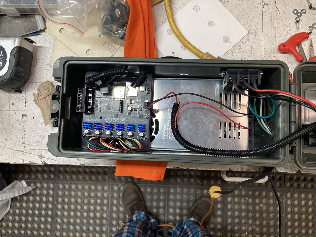
A pic of the JP3 setup in my control box. Using a 24V power supply.
Looking at the pictures, you have some super clean wiring. My one suggestion is flipping the end stop loop the other direction so it is not directly in front and on top of the wifi antenna sticking out of the board.
Thanks Ryan. I unplugged the limit switches temporarily so I can move the loop. I uploaded the config.yaml file and then tested and the x and y work.
I have a new problem, hence the disconnecting the limit switch plugs as a precaution. I have a warning saying I have an active limit switch on z. I don’t have any limit switches connected yet and only had the plugs connected for future. Nothing connected to the external plug coming out of the control box. Z axis will not move now. X and y are great.
Make sure it gets decent airflow, and keep an eye on the stepper temps. Do not let them get over 50C. If you have a ramps board, you could have any random steppers. So you probably need to adjust the current and holding current to keep stepper temps safe and sane.
You have a jackpot board directly over the fan in your 24V power supply in a box with a lid. I’d pay careful attention to cooling as that may be fine or may be a problem depending on the thermals in your system.
You should do a wireless signal strength test with that box open and again with it closed. I’ve seen an ammo box that severely attenuated WiFi, so it might be fine or it might be bad. Test to see the signal strength either way and let us know what you find.
I was going to say something about the power supply fan but, the jackpot only pulls like 0.8A at most, so I doubt that power supply will ever even turn the fan on. If it does it will be nice and cool as long as there is ventilation in the lid.
Thanks for the input gents. Cooling holes are drilled into the front wall of the box. I am looking at how to best put a case cooling fan into the box so it draws air across the cooling fins on the drivers.
Good catch on the driver power as well as I forgot to do that. Will do that before proceeding with more test cuts.
I think I will have issues with the wifi. Dropped twice on me with the lid closed while doing some test runs on the steppers. Box is plastic but still interfering I fear. Can I just connect through the usb-c and use fluidnc thru that? I will have to look into that deeper as I also want to use the cnc for a plasma cutter. My table is set up for both router and plasma and I designed and printed a plasma holder for my plasma handle. The cnc is mounted on a plasma table and the waste board set on toop for the crouter. Just haven’t tried that part out.
Moving the wires away from that antenna should surely help with signal. Unless that plastic has a filler, you should easily get a signal within 10 feet. You do not need to keep a connection you only need it to start and resume a job.
A USB is possible but it adds complications.
You can always just print my jackpot box and screw it in next to the box and keep everything else inside. My box has good airflow, wire management, and a fan spot.