That GPIO output is not sized to run a fan. I’m a little surprised it works at all, and if it does you won’t get any meaningful airflow through the 5V fan- just as you report it doing.
With that setup, you could end up blowing the 5V GPIO.
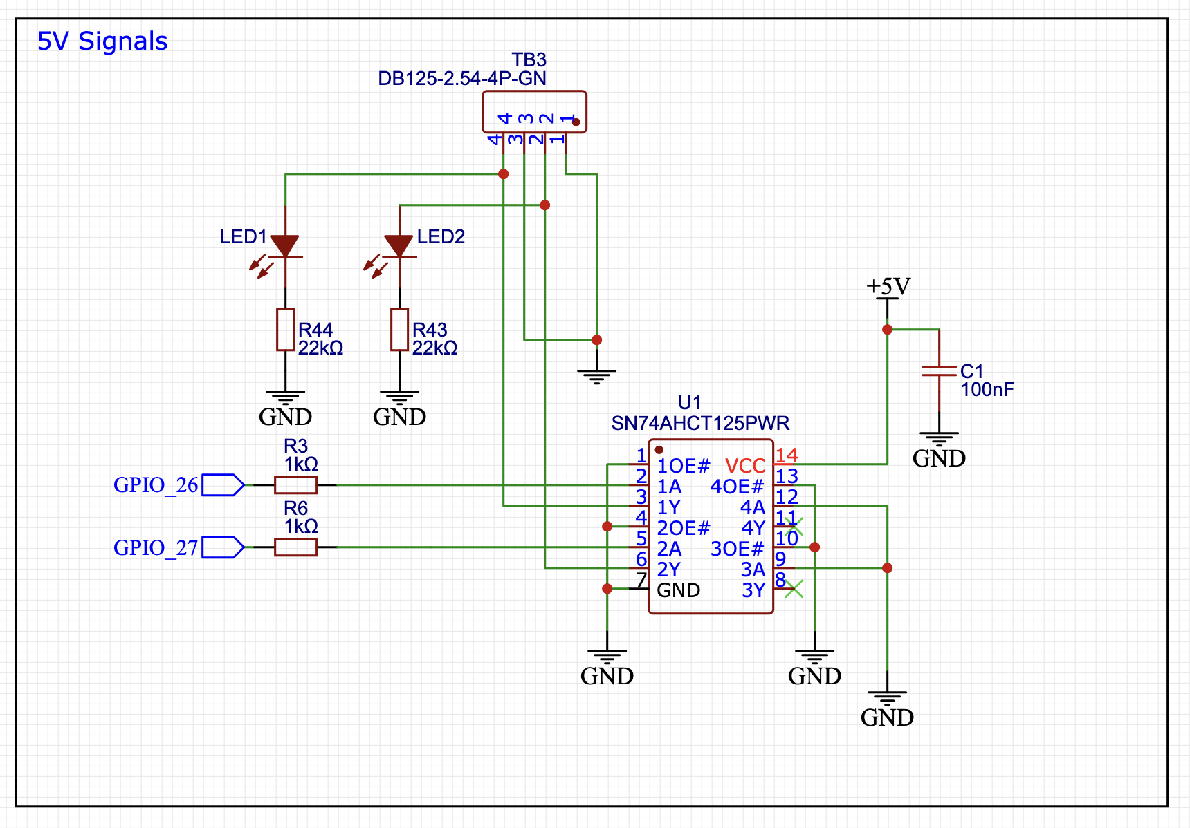
On Jackpot those are buffered, so you won’t also blow up the ESP-32 if that happens.
It’s not technically bad to plug a 24V fan into the MOSFET outputs. (If you match the fan voltage to the jackpot power supply). If you do this, then you’ll need to configure that MOSFET to be on at boot. Then…
You may find you want those MOSFET outputs for running a spindle, or mist cooling, or whatever- so it’s way easier and way better from a configuration flexibility point of view to just wire the fan to be on when the board is on.
I probably made the same mistake in the past. I’m not an electrical engineer, and several here are, so I stand to be corrected, but I think the 5v GPIO mosfet things are more for merely sending a signal (start or stop or “this much right now”) rather conveying power for consumption. A bit of info besides how many volts the fan runs on, is how many amps does it draw. And that’s the part where it may well outstrip what the 5v GPIO mosfets are designed for.
The larger board voltage fets can handle a bit more current but the 5v ones are just for signal not a fan. Like Jim said though a 5V fan is not a good idea anyway.
These aren’t designed to flow any significant amount of power at all.
Further, note the 1K Ohm resistor in series with the ESP-32 GPIOs. It makes it pretty unlikely you could blow up the ESP-32 through the buffer with just a fan motor.
You’d be hard pressed to sink much more current through these than a bright LED, let alone a good fan. The recommended current is only 8mA, with an absolute maximum of 25mA per output.
Thank you also to warn me about that blow up thing :S My spindle motor is an AMB 1400fmepdi. I have 3 wires from the speed controller to plug onto the jackpot board and I’m not realy sure about how to do it. Here are the specifications :
brown wire : 10 - 26 V DC for power supply
green wire : 0 - 10 V DC for speed control
white wire : 0 V for ground/ GND
Where should I plug those wires ? I supposed green is VMOT on one of the 2 mosfets outputs ? Can I plug white on any GND input ? And where should I plug brown ? ><
We’ll need to look over the specs for your spindle, and I won’t be able to take a look just yet. Hopefully someone else in the community can take a look and get you an answer.
@MakerJim Thanks for the correction! I know either only enough to be dangerous, or not even that much. Which is to say, I don’t really know the difference between buffered and mosfet. I comprehend the difference between a purpose of sending a PWM signal versus that of sending power for consumption to drive an electromagnetic fan. Not much more than that!