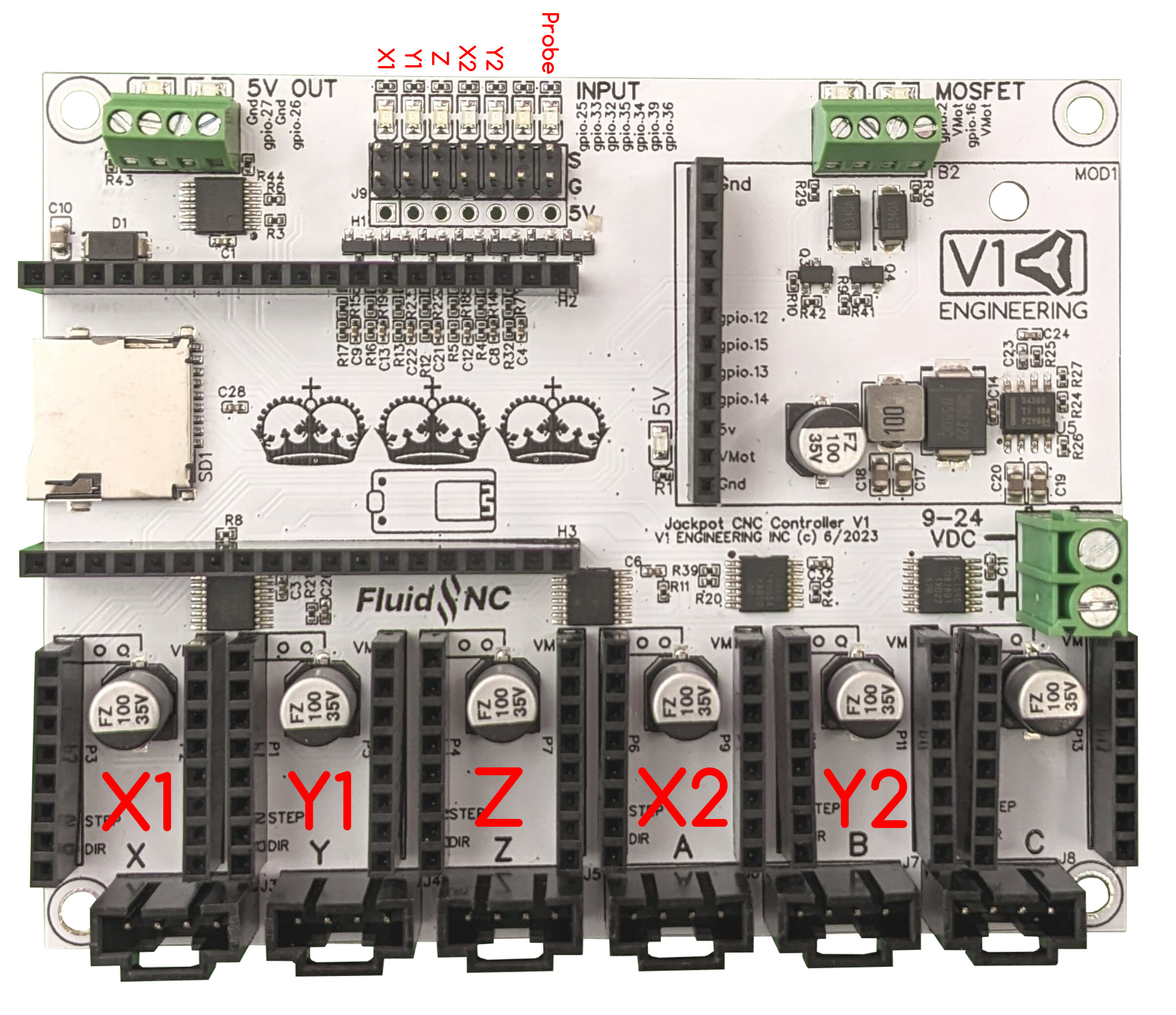
On the Jackpot, the “MOSFET” output area has the following explanation:
2x Line level outputs (same as input voltage)
PWM Capable
The MOSFETs switch to ground. You can use any voltage up to the VMot max as the positive, as long as it uses the same ground reference.
Can be used to drive 2.5A continuously before they overheat. You can use them intermittently up to 3.5A. If using above 2.5A you should test to see if they start to overheat.
They can be used with inductive loads (solenoids, relays, DC fans/motors)
I’m looking to connect a teensy 12V Noctua cooling fan - this one: Amazon.com
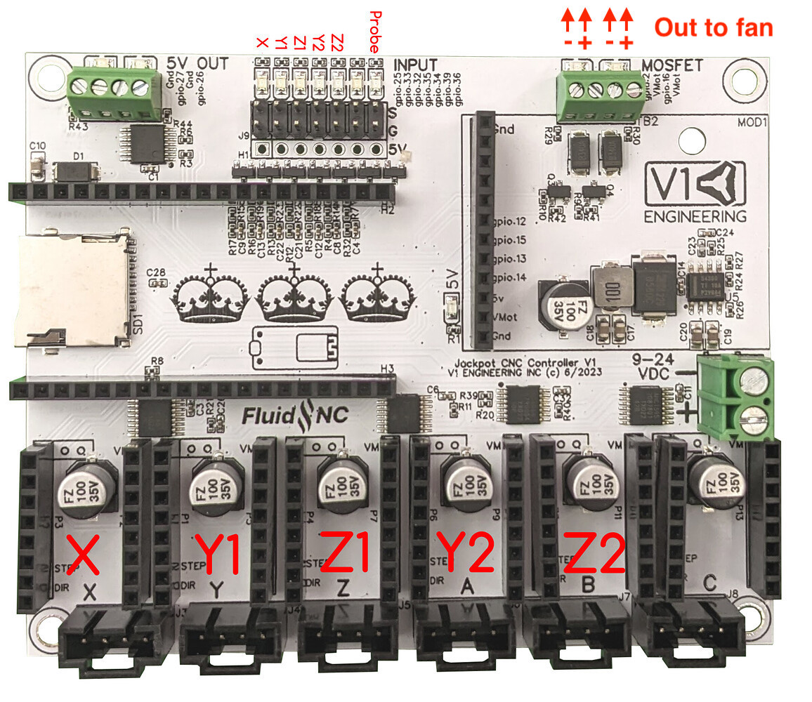
Based on what I’m seeing, I * think * I’d be connecting the “positive” wire for the fan to the one of the two “VMOTs,” and the “negative” wire to the adjacent slot — either GPIO.2 or GPIO.16.
Is that correct? And if so, is there any reason to choose one of those GPIO’s over the other?
Are you running 12v or 24v on your jackpot? Those mosfet’s give whatever voltage your power supply is. So for a 12v fan is going to get some RPM if you are running 24v LOL
I’ve never been a big fan of wiring 12V fans in series to try and run them at 24V. There are two failure modes added, both of which have happened to me and neither of which is good.
If one fan fails open, then the other fan stops running as well because it is in series with the other one.
If one fan fails shorted, then the other fan burns up because it now gets 24V instead of 12V.
FWIW, I just connect my fans to the incoming power. They are always on when the tool is on. Those fans are so quiet, you barely hear them when the system is idle.
The problem is, even if you find gpios for one or two fans (the tinybee has dedicated pins for two fans), fluidnc does not have a functionality for controlling fans
You can’t associate a fan power with stepper activity, there’s not even a static cooldown fan functionality
You will need to use the “mist” an “coolant” commmands to control the fans, and use a startup macro to run them on start…
Even with this, most post processors will shut down the coolant and mist at the end of a job, wich becomes a problem too for the static case fan…
Wiring them to the power input, matching input voltage IS the simplest way I think
Lately I’ve had a lot on me, and I’ve been putting in long hours without much sleep, and it really impacts comprehension and IQ in general. Thanks for tolerating the “sleepy version” of me.
I have edited the FAQ on the Printables listing to mention that connecting the fan straight to the power supply that feeds the board is a simple and good way to do it. The FAQ answer currently reads this way:
A: One of the easiest and best ways is to not connect the fan to the board, but directly to the power supply that feeds the board, since the volts must match anyway. Nevertheless, I connected mine to the board. The Noctua fan that I used runs on 12 Volts. However, the method I used can work with fans made for either 24V or 12V. — The key is that your fan’s voltage must match the main power supply voltage. (Most people will be using 24V power, so that would mean the fan needs to match the power supply, at 24V.) — I connected my fan straight to a spare “MOSFET” port on the Jackpot board (which, again, will match the power supply, presumably either 12V or 24V), so that every time the LowRider gets switched on, the fan comes on. It doesn’t do temperature monitoring for going on and off. It stays on whenever the LR3 is on. It was simpler for me to do it that way. Please see the port options highlighted on this schematic:
I was just studying your Jackpot case with acrylic lid, thinking of how I might modify that or do similar to improve the really cheesy mount I used to put the Jackpot on my JL1.
Your contributions are very much appreciated.
I just bought a 24v fan and it’s wired directly with the power in. When the machine is up the fan is running, when it’s off it’s off. I didn’t see a need to switch the fan separately.
Hi everyone ! Thanks for all those answers. I have a 5v fan. Is it possible to plug it on 5v outputs instead of using a 24v fan on mosfets ? I tried but the fan is not working. Should I change something in the config.yaml of the board ?
Jackpot has GPIO 5v outputs but those are not sized or intended to directly run a fan. There’s also 5V out on the expansion connector, but again this is not intended to run an electrically noisy fan.
No. A 5V fan is the wrong option.
The way to run a fan, in my opinion, is if jackpot is on the fan is on.
The best way to do that, and what I recommend, is to get a fan rated for the jackpot input voltage, and wire the fan to the input voltage. In this case, get a 24V fan.
All right thanks for the answer I managed to start the fan by sending G62P0 command but it seems it hadn’t enough power (it’s turning slow) … I agree with you it should turn on when jackpot is on ! I’ll get a 24V Anyway, pluging a fan on mosfets output is bad idea no ? I have a PWM spindle and I want to plug a laser in the futur. I’ll need the 2 mosfets outputs isn’t it ?