Running a macro makes the pendant disconnect? I tried the disable motor and turn on an output.
The inductor on the 5v PS still gets pretty warm. It is rated at 5.5A. looks like the m5 pendant runs off the vmot circuit, that is much better.
Running a macro makes the pendant disconnect? I tried the disable motor and turn on an output.
The inductor on the 5v PS still gets pretty warm. It is rated at 5.5A. looks like the m5 pendant runs off the vmot circuit, that is much better.
Yes. M5 runs on 24v where the CYD runs on 5v
The inductor is rated at 5.5A, the buck converter is rated at 3A and is not warm.
Pendant is running at 0.19A@5V.
Maybe I am overthinking it. No pendant the inductor still gets warm. I will check a jp1 vs jp2 to see if there are any differences in temp
any idea what is up with the macros?
Do you have any macros loaded and do they work? I hit the macros screen, they take a minute to read, if I hit load the macro does not run and the pendant loses connection. This is with the latest 3.9.8
Unfortunately no. I don’t ever use any macros. I am more of the KISS method lol. But I can load some on there and test if you need me to… or hell they might already be there and I just don’t know it lol
I am testing a board with no pull down to make sure that is not the issue.
So that is odd, it shows my loaded macros. With a SD card in it just says “empty file”, with no card it crashes the pendant. Either way it does not run the flash based macros if I hit “run”.
So that is pendant thing, not a Jackpot thing.
edit - " Macros don’t load If you get a “Reading macros” message displayed, but the macro never load, you probably have a missing or incorrect file on the FluidNC ESP32. You need a file called macrocfg.json if you are using WebUI 2 or preferences.json if you are using WebUI 3. Use command $Localfs/list to see the contents of the ESP32 file system. Send $localfs/show=\<filename\> to see the contents of the file."
I am pretty sure the macros do not work with webui v3 and the pendant. no matter what it is checking the sd card. I will try out webui v2 real quick
Okay the pendant, webuiv3 macros are broken. I can load my v3 macros with files and they work as expected even in the webuiv3. lame.
The inductor on the jp2 is larger and does seem to get more hot than the jp1 inductor. on the jp1 the bottom of the board is hotter though so maybe this larger inductor on the jp2 is pushing more heat out the top instead of the pcb. I would not mind it being cooler though, add a heatsink, redesign the circuit?
Everything seems to work. I need to start soldering on 100 resistors for the pendant pulldown, maybe offer the first batch at a discount with some hand numbering and signed? Special edition, ![]() ,
,
Put me in to buy the first three signed and numbered ones. I’ll prepay if you like. ![]()
Edit- should we do some tests with other expansion modules? I wonder what the pulldowns do to things like the 0-10V module. Maybe nothing.
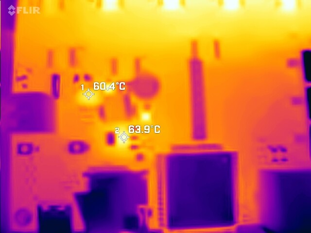
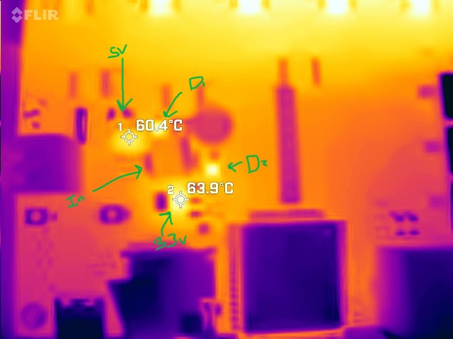
Okay so it is not the inductor. It is the regulators.
This one has been on for a few hours with zero airflow so worst case.
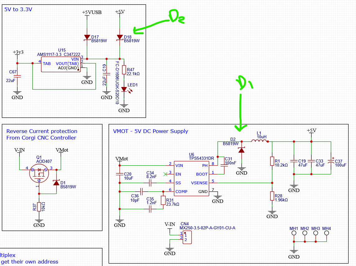
Should those diodes be working that hard?
That is only on gpio12, it is the only one that really matters.
I can’t help but wonder why the PS stuff is so warm, as in did I screw something up, I only added the diode, D2. On the other hand, the board itself is much much more warm because of the drivers that are sitting here cooking everything (no heatsinks on these right yet). So is it additive, or are the regulators just hotter (the surrounding pcb is only 7-8C cooler than the hot components)?
I need AI to be able to test my circuits. Learning how to use the built-in tester stuff seems like a whole new career.
Put me in for #4 please! I will also prepay!
Of course I don’t have any 5k resistors. (or if I do I can’t find them)
Amazoned a selection, they’ll be here Friday.
1k-5k? anything in that range? Hope this fixes yours as well.
Yeah, probably. It’s just another thing to test as a way to ensure we know what the problem is.
As a temporary measure, give that a shot for sure. It won’t likely be a valid fix going forward, though.
Bear in mind that this is only working because the pendant is also booting and taking a longer or similar time to boot. A software driven reset or change in boot timing with future firmware revisions may break this again.
Thanks for the info.
I just double-checked, for now a software reset still works.
If that is the case. I am sure there are several pins on the 6pack controller that could cause issues if the boot timing was messed with. If it changes, I think I could show this to Bart and figure out a pendant boot delay or something.
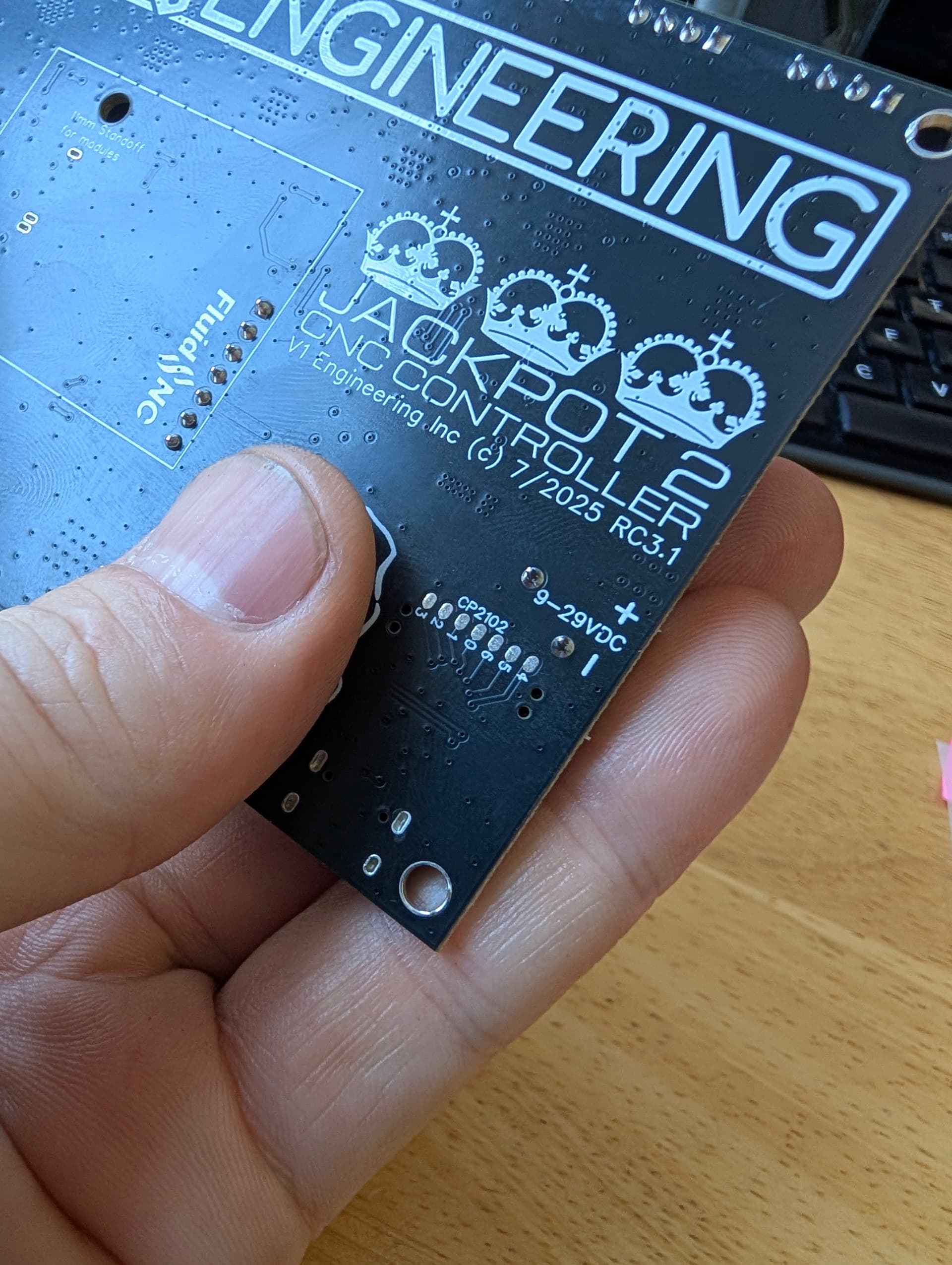
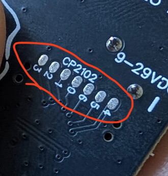
So for the rest of the discussion- what Ryan’s actually pointing out is that he did something really cool for me or anyone who does any funky testing with these things.
On the V1E ESP-32 module, Ryan broke out the extra IO on the CP2012 chip to pads, which means you can use those ESP-32s not only as ESP-32s, you can use that extra IO to do all kinds of cool test things with the module.
The V1 ESP-32s have thus gone into some really cool places that have nothing whatsoever to do with CNC machines.
Here, Ryan put those very same test points in the JackpotV2, so if someone were wanting to do some automated test of the system, it’s an option.
Really, really awesome of you, Ryan.
One day you can whisper the answer in my ear.