What’s the specific issue here? Have you done anything to conclusively show that this is the issue? Is this something you’ve tested or just a hunch?
From looking at the Espressif docs, it appears that GPIO0 just needs to be held high at boot, either by its own weak internal pull-up or by whatever it’s externally connected to.
The easy approach to pins like that is to use them as outputs and make sure that they’re ok with being pulled in the right direction during startup. I would have said a UART Tx was a very good option there and this looks pretty similar to how I would have approached it.
I might not have a complete enough picture of what’s going on here, but I certainly don’t see anything here that would convince me that a layout change needs to happen. Some extra investigation or a couple of changes to components etc. to verify things, sure…
Now that we added the pullup, they all boot and flash perfectly fine. Now the odd boards are showing weird $ss messages. So Now I am getting more and more “bad” esp’s because I am not going to ship them if they repeatedly show incomplete $ss messages. Oddly Sometimes they work perfectly fine…after making stepper move a bit.
This does also vary when the Steppers are connected or not sometimes. So it is either a bad pin choice, or that pull up is too strong? Not sure. Or are these esps that are just bad and without the pullup they would not have flashed anyway. Was the pull up a waste?
How would I test that. O-Scope the TX and RX pins and look at the signal?
Logic analyzer?
I guess that could be a good first real test. Currently, I am just making a pile of funky esp’s that almost work. Not seeing any obvious resistance differences on the good and bad gpio0 pins. Maybe I should also check the Rx pins.
From the driver spec sheet “Baud rates from 9600 Baud to 500k Baud or even higher (when
using an external clock) may be used. No baud rate configuration is required, as the TMC22xx
automatically adapts to the masters’ baud rate”
What do we actually need in terms of speed? This is all I am seeing regarding speed Axes | Wiki.js
So the pull-up was added at some point partway through and that fixed the booting issue? That would make sense, the internal pullup will be extremely weak and needs to be able to charge whatever capacitance is connected to the pin before the boot occurs.
As in there are some boards doing this or are these the same boards that were showing issues before? How is it weird? Garbled characters, missing sections, starts responding partway through? Does it only do it to the first if you repeat the message a few times?
That does sound odd. I think it’s important to try to accurately verify exactly what the failure conditions are and try to nail down exactly what affects it. If you’re trying to keep combinational stuff like that in your head, it’s possible to get lost in confirmation bias. The best scenario is if you can reduce it to a specific course of actions that make it fail 100% of the time. Something like ‘If I power up the board from cold and $ss doesn’t respond with a complete message, I can move a stepper motor and then $ss will always respond with a complete message’. That’s something you can start to tease out the different effects and see where they’re related. On the other hand, if it’s ‘I power up the board from cold and if $ss doesn’t respond properly, moving the stepper motor and then trying $ss will respond correctly 50% of the time’, then I’d say they may not be related and just to try it again without moving the stepper motor. If it’s a case of moving the stepper makes it work 50/50 and not moving the stepper means it works 0% of the time, that’s still a valuable thing to know, you just need to do it 10-20x as often to be sure that it’s actually a real effect and not just luck. Otherwise it’s like flipping a coin 10x and concluding that because you’ve only seen heads that your coin is broken!
A bad pin choice doesn’t sound right, to me, but I learned long ago that it’s always better to devise a test procedure to prove that it’s not something wacky than to discount it outright. Obviously test the easier/more likely stuff first, but never discount something because it ‘surely can’t be that’, etc. Pull-up too strong is definitely possible, I’m not super familiar with the drive strength of the ESP32s. This is where I’d normally say that’s an easy test by getting a scope probe on there and taking a look. Alternatively just drop it to 10k or even 22k and see what happens. Is that something you’re able to do?
Exactly! It could well be some kind of power supply issue causing a slow voltage rise on startup that changed the balance with that weak internal pull-up. It could be something entirely different.
I would never say it was a waste. It may not be needed, but everything is always a balance. Putting it there isn’t a big cost driver and is a conservative/defensive design decision. It may make zero difference, but if it doesn’t then you’ve only spent a couple cents extra per board. If it prevents problems even 1% of the time, it will be worth its weight in gold. Also considering that things need to be thought of as 'does it work on my bench, on someone elses bench, on 12V vs 24V supplies, on supplies with lots of ripple, in places with significant EMI, when the ESP32 is cold, when it’s hot, when it’s a cold boot vs a hot reboot, when it’s a hot reboot and the pin might have been at 0V when rebooted or at 3.3V. When the ESP32 input is at the low end or high end of its sensitivity specification, etc. In super detailed high-end designs or where the fix for an issue might be super expensive, we take ALL of that into account in one way or another and devise tests to make sure that things work in all those conditions. In the vast majority of circumstances or if it’s something like adding a pull-up, you add the pull-up and move on with your life. Consider it like designing a bridge. If you’re a hardcore professional and it’s a hugely long bridge on a tight budget, you do a huge amount of design work. If you’re a home-owner/DIYer and you’ve got a small creek to get over, you likely just over-build the shit out of it, slap it once, say ‘that aint falling down any time soon’ and move on with your day!
Could well be. In that case, writing a basic test firmware that just spams a message out of the UART could be useful to see if it’s re-creatable.
Yes to both of those things. Scope zoomed in to check that the waveforms going in/out of the ESP32 are crisp and square-wave looking with no glitches on the edges or ringing. Logic analyzer or good scope with good memory depth and serial decode to see that frames are being formed correctly, no doubled edges, timings are stable, checksums are correct etc.
How are you checking that resistance? I wouldn’t expect that to show anything useful, to be honest.
Another great option. Is this a hardware or software UART in the ESP32? Software UARTs are notorious for falling over at times when the software has too much other stuff going on. If you’re seeing ESP32s fail to work properly immediately after boot, maybe there is some other setup stuff still going on in the background or something that hasn’t timed out completely yet taking up cycles.
Again, separate it into testing vs fixing the issue. For testing, do the most extreme thing. Change it to 9600 baud and see what happens. If the comms issues go away but the drivers start doing weird stuff due to slow comms then that’s a huge win, evidence wise.
The flashing process should include some form of read-back verification step, so as long as the flashing completes successfully, you should be in identical scenarios either way. If the flashing process doesn’t do that, I’d frankly be horrified.
Never garbled. Missing sections if repeated different sections can be missing.
Working on figuring it out. It is definitely not the same for all of them. I was releasing them if they worked with the steppers plugged in. If it took moving the steppers first, that is a bad esp. Now I am holding both for more testing. Testing a couple more things.
interesting.
Okay when I have time to set up and be in a clean space I will dig deeper. I am about to have to make both LR and MPCNC kits that is going to make a mess. Bummer when they run out on the same day.
I found a particularly bad one, I can test the baud rate real quick.
In some ways, asking Ryan to clarify exactly what’s going on is also a bit of ‘rubber ducking’. Having to explain the problem concisely often results in needing to revisit assumptions and can be a powerful way to re-examine a problem through re-framing it.
Okay on this particular one 9600 did not change anything. I tried flashing it on and off the JAckpot, this is a bad board for sure. This is a good one to test deeper for sure. It always shows a lot of missing info in $ss, and most of it, it does not even see the right number of drivers.
Missing entire sections? That is extremely interesting. So where you’ve got a line like:
[MSG:INFO: Compiled with ESP32 SDK:v4.4.4]
You’d be missing an entire line but never part of a line? Is it always the same parts missing, like it misses the first 2 lines?
If so, that doesn’t sound like a hardware issue to me. A hardware issue would be characters missing or being clearly wrong, or maybe an entire segment missing and then coming back but it would be unlikely to be aligned with line ends. After all, there’s usually nothing special about a line from the hardware standpoint, it’s just another set of characters that get sent telling the terminal emulator how to display it and then a pause in the lines changing state, perhaps.
Also,
What the hell does that sentence even say? I can only apologize, I’m currently stuck at home with a fever so who knows what’s going on…
Can you post up a few examples of that? Some context here might help.
For sure, and I do appreciate it. Honestly, I’m not likely to crawl back through them, especially as I currently feel pretty wretched, but hopefully my contribution is valuable enough to be worth the effort to bring me up to speed!
Ok, interesting. I might have missed something obvious there, most of my responses were assuming that this was the UART you were talking to the ESP32 with, not the UART going out to the stepper drivers.
That would change things a bit. That’s definitely a case of get a scope on there to make sure the waveforms look good, then get a logic analyzer on there to make sure the timings are correct and that the messages in both directions look good.
There are quite a few differences with those messages and some of the differences aren’t stepper related, right? I take it on a good board, that should be the same every time and contain essentially all that info?
Okay, I have a little one I have been dying to try.
That and a lot more.
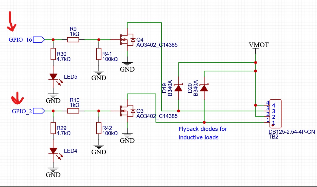
P.S. While looking at that bad one I realized all the clone esp’s are missing the three TVS (diodes?) on the USB lines. The pads are there but no components. Interesting way to save $0.03
Yeah, cost reductions like that are always fascinating. It quite asymptotic where even small decreases in price require significant decreases in quality/performance etc.
Given that the CP2102 doesn’t give any specs for its ESD susceptibility, I’d be nervous to remove them.
It’s one of those things that is just rolling the dice, really. I always get quite nervous about ESD related issues because it’s often not just something that can kill electronics, it can also cause things like inputs that get ‘leaky’ and need a lot more current to drive, or situations where thresholds have changed like an input that now needs higher voltage to go into the ‘high’ state, or an output that has higher impedance and doesn’t drive its pin as strongly any more etc. Often the worst case isn’t something that’s obviously dead outright, but something that starts to fail intermittently and potentially degrades over time.
It could be a reasonably good proxy for evaluating the overall quality of the board, I’d guess. The pads will still be there because likely the design is lifted from the original version and it’s more expensive to re-do it to remove them than it is to just mark them DNI on the BOM.
Maybe start by spending some time with the scope/analyzer looking at what it’s like on a good board, first. That’ll ‘get your eye in’ somewhat for what it should look like.
If you can grab captures, post them up and I can probably point out if there are any aspects that need closer evaluation.
I’ll also be out for a few days at some point because I’m heading out to visit my parents once I’m over whatever this illness is. Will be getting to see my Dad’s partially completed LR3 which will be interesting. Worst case, send me a PM so I know there’s something to look at.