After replaced the SKR Turbo 1.4 with the jackpot appeared some issues, that I think are all connected.
When I release the emergency button(I normally use it as shut down) the board start to blink and make noise from the steppers, if I disconnect at least 3 steppers the board start.
Another problem is that the steppers are not fluid at all, seem like they are grinding, and make a bad noise.
With the machine not powered, if I try to move an axis, it correctly resist to the movement, but not in a fluid way like with the skr.
I’m from Italy, I don’t think a swap will be a cheap option🥲
Anyway, if you provide me detailed info about the resistor and where to solder it, I can do it.
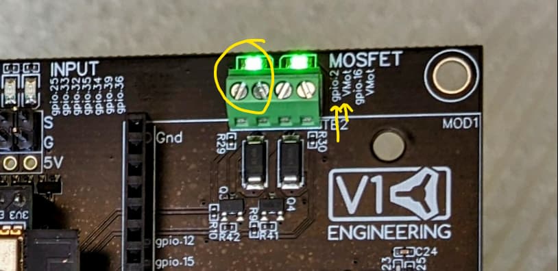
Another question, how can i use the “mosfet” exit for the router relay? I was already using a 24v relay before, and I don’t want to change it
No the USB-c version is worse. Most of the micro usb versions do work.
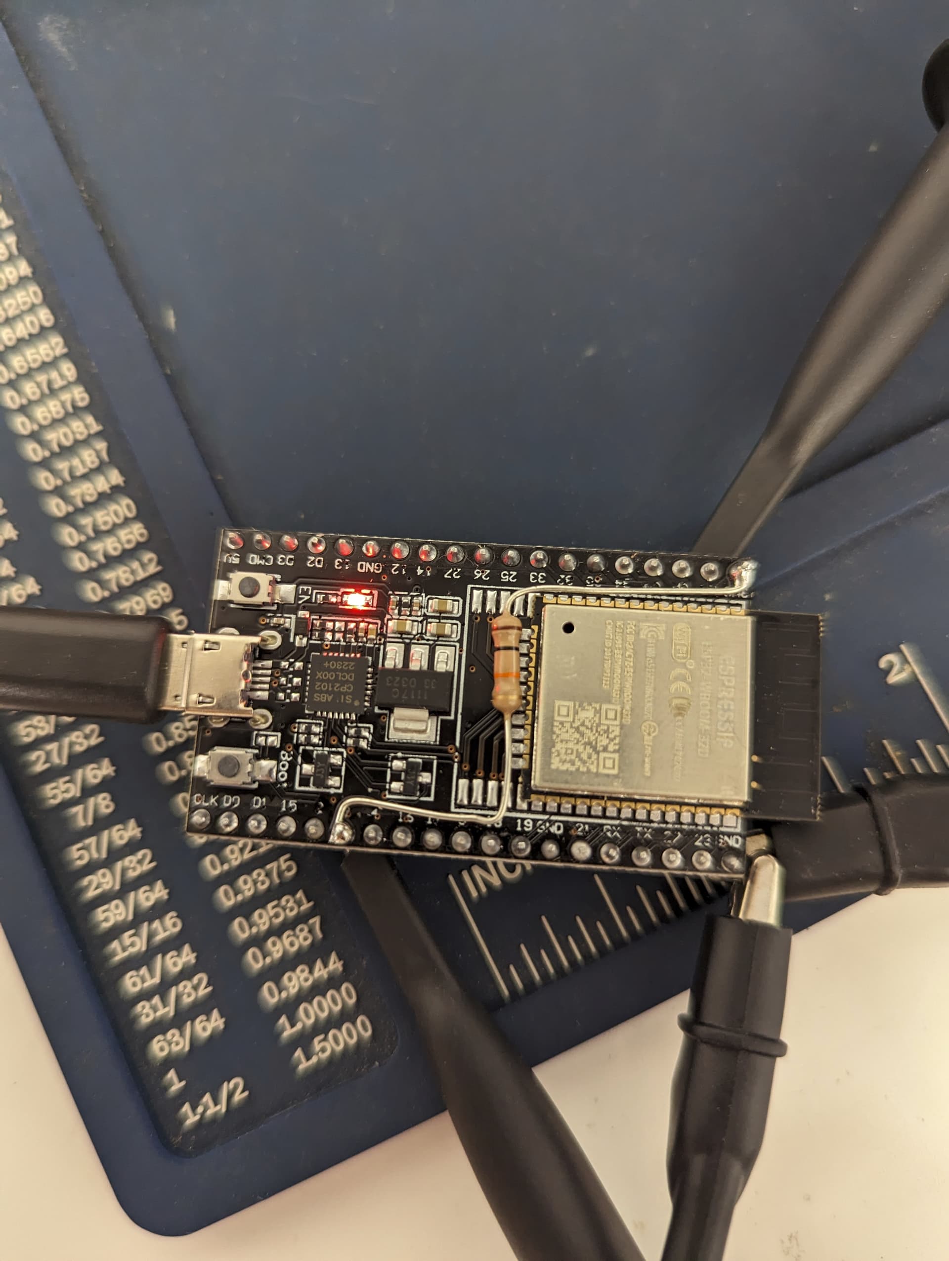
It is actually pretty easy, from the 3v3 pin to the 0 pin, with a 4.7k ohm resistor. Here is a picture (with a different value resistor I was testing).
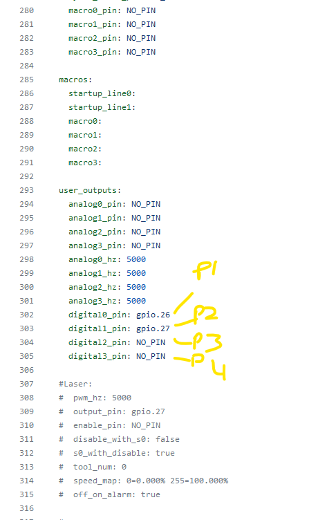
In the yaml you can change the output to any pin you want. I have the gcode example on the instruction page.
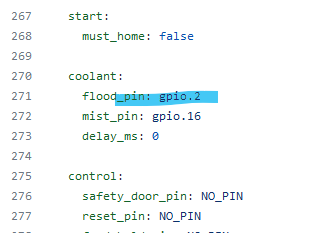
If you can be more specific to what part you are not sure about I can help a bit more. It is already set to one of the 5V ports, just change the yaml pin to a 24v port.
There’s a trick I use when soldering leaded components like that.
I find some wire that is roughly the same size as the lead of the component, then strip the wire in lengths long enough to go from the component body over to the pin where its’ being soldered. Preferably teflon jacketed wire, but you can use what you have.
Put that jacket from the wire over the bare lead of the component.
That leaves the long run of component lead not exposed, removing a shorting risk.
You an also use electrical tape or shrink tubing that fits over the lead before you solder it.
I’ll grab pictures when I rework the one I have on the jackpot on my JL1 (Which isn’t causing me any problems- but I’m going to rework it anyway.)
Ok, thanks, now I figured out how to use them. Tomorrow I’ll receive the resistors and will modify my esp. I found the blu one, not the brown, is it the same?
Seem like the 24v power supply can’t handle the start up and blinks like the board. If i disconnect the cable from the board, leave the 24v power supply to start, and than connect the board cable it seems to work… but i never had this problem with other boards. The power supply is a 24V 45W
Another think I can’t figure out: If I use the standard parameters it moves ok, but if I increase the max feed all starts to do bad noises, even if i run the machine below the 9000mm/min (as default).
With the SKR Turbo I usually have rapids set to 18000mm/min, and 9000 now seems slow🥲
We use very little power but if that is a overrated power supply maybe it is freaking out. 1- Do you have any others 45W or better between 9-24V to test just to see?
That is very odd tough. 2-The polarity is good?
3-Are you absolutely sure none of those heatsinks are touching any pins?
I have never seen one blink. 4-Try adding one driver at a time starting at B and work towards X to see if one driver in particular is causing an issue. (be sure to power off before adding or removing a driver)
This is something new. And for the record I am now testing them all with the esp and drivers fully populated, sorry you got one before I started that. At that point I was just testing every couple with drivers but I did test with the esp on the jackpot and fully booting up (so the drivers or the power supply should be the issue here).
5-Also while testing please unplug the relay from the 24v pin (that could be drawing more power than you think).
6-If the yaml edits went wrong it could also be booting with an error. You might want to pull the esp and boot using fluidterm to verify there are no config errors.
We should really get the board working with my configs before you make any edits or we could be working on several issues at once.
I tested the setup with a 60w 24v PSU I had and seems to work… more test will follow, even remove the resistor. Maybe the problem is the 45w psu, but with the other boards never had problems.