Jackpot 3 - MPCNC - endstops autosquare setup: Error

New Jackpot 3 MPCNC endstop setup. When I try to home any axis, I get the following error: “Homing fail. Pull off travel failed to clear limit switch.” I have to restart the board to clear it… I have played with the Pull Off values with no change. @vicious1 ? Also, What settings in the config.yaml turn on the dual endstops / auto square?

error

Did you maybe swap the endstops on X/X? Then it tries to drive the wrong one back.

Tjx. I’ll give that a try.

Should have been X/Y… I posted from mobile… :stuck_out_tongue:

If your pulloff is set to actually clear your switches after trigger, they are either plugged into the wrong or wired no vs nc.

If you trigger one by hand when homing does it go in the negative direction, does that stepper stop moving?

1 Like

Homing errors before either x or y steppers move. Jogging x,y, and z work. So steppers seem to be wired correctly.

Endstops do not seem to be correctly wired on your build.
Use the $Limits command and manually trigger each endstop one at a time and correct them.

1 Like

That typically means you wired the switches incorrectly.

Well… I bought the Tiny Touchplate a while ago when my homemade one didn’t work. I connected it directly, as instructed, and it gave me the same result. It would start the homing, but not trigger. Feeling frustrated, I turned it off and walked away. It has been a few weeks. I fired it up today. Now it doesn’t see my x or y endstops. It does see Z. But I can’t home that until X and Y are homed. I’m afraid I zapped the board somehow. Since one of the capacitors fell off when I received the board, I feel like this whole upgrade has been cursed from the start. :slight_smile: Before I order another JackPot 3, Any help or advice is welcome. @vicious1 just a suggestion, on your next Jackpot version, use JST connectors.

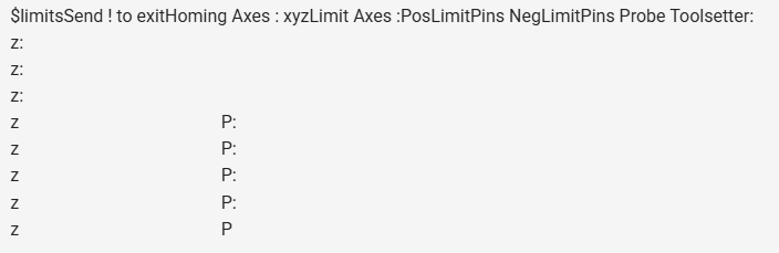
Use the terminal in the WebUI and use the $limits command to test all your inputs. This will give you a live view of all your inputs so you can test all switches, including your probe.

Lets start there as I am not sure how the probe could pop all the inputs. If it did, they can be fixed with a component swap.

yes, First thing I did today. Only shows Z now.

You’d be well served to post screenshots or terminal copy/paste.

Are you saying that your ran $Limits and pressing each of the limit switches one at a time, the only one that shows up at all is Z (not z?).

Copy / paste the output of $SS here as well. Use the preformatted text option on the forum editor toolbar. It looks like this: </> .

From your first post it looks like you edited your config.yaml file. Have you put the stock one back on? We have not seen 4 popped endstops on a board yet, I really hope that is just an odd config file or something because you should not be able to pop them all at once.

Can you upload a picture of your board as it is wired up please.


I agree with Jim it would be nice to see the $ss.

I went back to stock yaml. $limits shows all axis functioning correctly.

1 Like

$SS
[MSG:INFO: FluidNC v3.9.9 GitHub - bdring/FluidNC: The next generation of motion control firmware · GitHub ]
[MSG:INFO: Compiled with ESP32 SDK:v4.4.7-dirty]
[MSG:INFO: Local filesystem type is littlefs]
[MSG:INFO: Configuration file:config.yaml]
[MSG:INFO: Machine LowRider]
[MSG:INFO: Board Jackpot3 TMC2226]
[MSG:INFO: UART1 Tx:gpio.16 Rx:gpio.4 RTS:NO_PIN Baud:115200]
[MSG:INFO: I2SO BCK:gpio.22 WS:gpio.17 DATA:gpio.21Min Pulse:2us]
[MSG:INFO: SPI SCK:gpio.18 MOSI:gpio.23 MISO:gpio.19]
[MSG:INFO: SD Card cs_pin:gpio.5 detect:NO_PIN freq:20000000]
[MSG:INFO: Stepping:I2S_STATIC Pulse:2us Dsbl Delay:0us Dir Delay:1us Idle Delay:255ms]
[MSG:INFO: User Digital Output: 0 on Pin:gpio.26]
[MSG:INFO: User Digital Output: 1 on Pin:gpio.27]
[MSG:INFO: User Digital Output: 2 on Pin:gpio.0]
[MSG:INFO: User Digital Output: 3 on Pin:gpio.2]
[MSG:INFO: Axis count 3]
[MSG:INFO: Axis X (3.000,1223.000)]
[MSG:INFO: Motor0]
[MSG:INFO: tmc_2209 UART1 Addr:0 CS:NO_PIN Step:I2SO.2 Dir:I2SO.1 Disable:I2SO.0 R:0.110]
[MSG:INFO: Neg Limit gpio.25]
[MSG:INFO: Motor1]
[MSG:INFO: tmc_2209 UART1 Addr:3 CS:I2SO.14 Step:I2SO.13 Dir:I2SO.12 Disable:I2SO.15 R:0.110]
[MSG:INFO: Neg Limit gpio.35]
[MSG:INFO: Axis Y (3.000,2443.000)]
[MSG:INFO: Motor0]
[MSG:INFO: tmc_2209 UART1 Addr:1 CS:NO_PIN Step:I2SO.5 Dir:I2SO.4 Disable:I2SO.7 R:0.110]
[MSG:INFO: Neg Limit gpio.33]
[MSG:INFO: Motor1]
[MSG:INFO: tmc_2209 UART1 Addr:3 CS:I2SO.19 Step:I2SO.18 Dir:I2SO.17 Disable:I2SO.16 R:0.110]
[MSG:INFO: Neg Limit gpio.34]
[MSG:INFO: Axis Z (-147.000,3.000)]
[MSG:INFO: Motor0]
[MSG:INFO: tmc_2209 UART1 Addr:2 CS:NO_PIN Step:I2SO.10 Dir:I2SO.9 Disable:I2SO.8 R:0.110]
[MSG:INFO: Pos Limit gpio.32]
[MSG:INFO: X Axis driver test passed]
[MSG:INFO: X2 Axis driver test passed]
[MSG:INFO: Y Axis driver test passed]
[MSG:INFO: Y2 Axis driver test passed]
[MSG:INFO: Z Axis driver test passed]
[MSG:INFO: Kinematic system: Cartesian]
[MSG:INFO: STA SSID is not set]
[MSG:INFO: AP SSID FluidNC IP 192.168.0.1 mask 255.255.255.0 channel 1]
[MSG:INFO: AP started]
[MSG:INFO: WiFi on]
[MSG:INFO: Captive Portal Started]
[MSG:INFO: HTTP started on port 80]
[MSG:INFO: Telnet started on port 23]
[MSG:INFO: Probe gpio.36:low]

x and y homing work just fine.

One point of confusion, On the Jackpot3 CNC Controller - V1 Engineering Documentation page, the image in the Endstops section, shows Z on 32 for MPCNC. but in the line under the image on the page, it says, “The probe/touchplate plugs into the last port (gpio.36), on either configuration.” I have tried both pins, same result.

The MPCNC does not have a Z endstop. The probe should work on the last plug though.

$limits does not show a “P” when you use the last set of inputs?

sorry, editor is ordering all the tab spacing in text… saved as an image