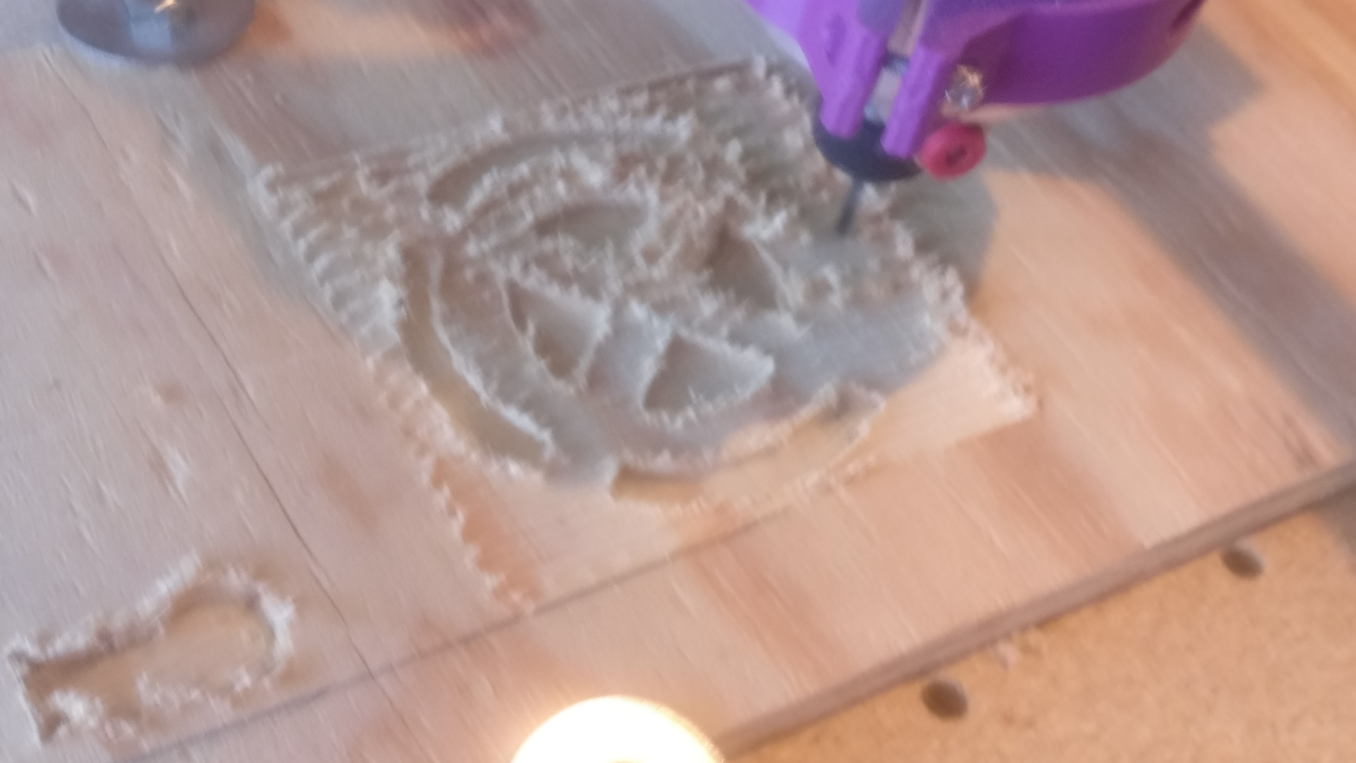
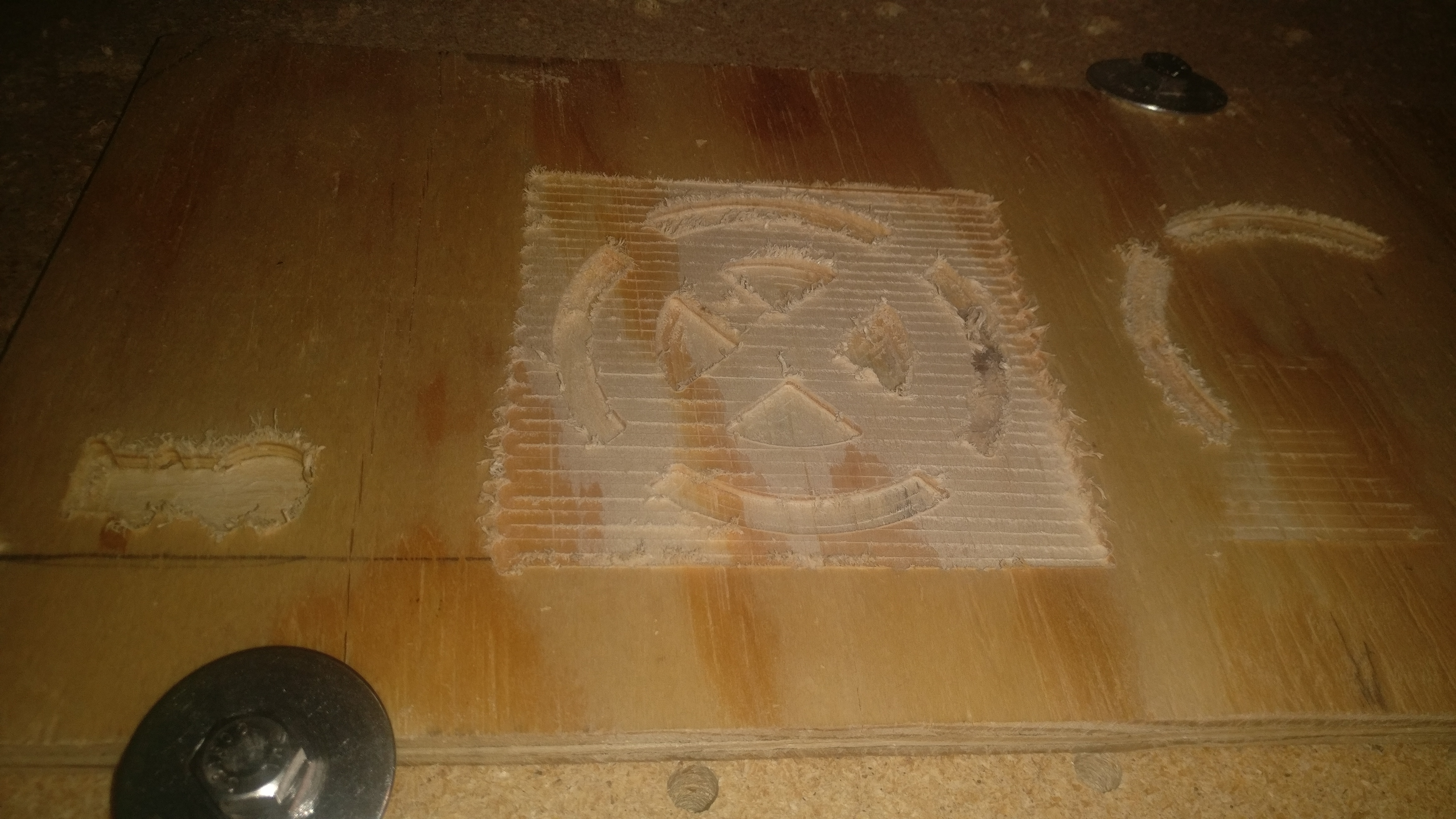
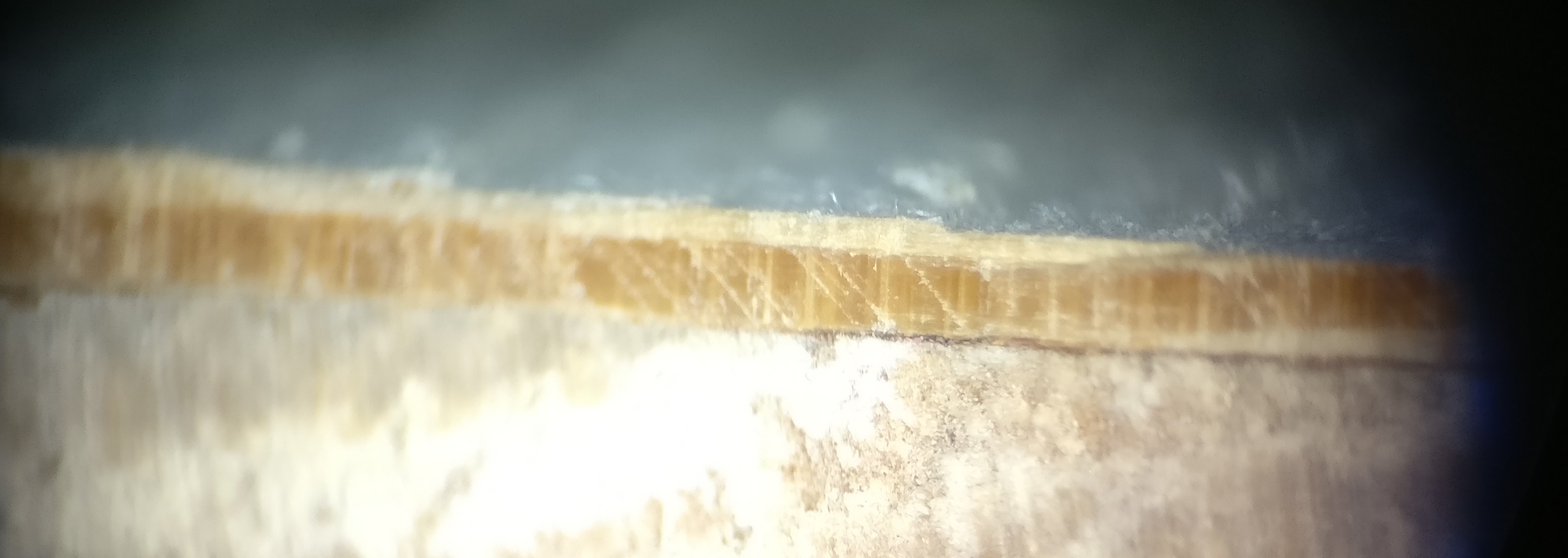
I’m trying to do some facing cuts with my MPCNC but I’m getting some issues with ridges being left on the surface, I’ve tried adjusting the tension of the bolts for the z-axis but it doesn’t seem to make it more vertical.
I’m sure there is also an issue with my speeds and feeds, this is literally my first cutting since I’ve built it ( other than putting holes in spoil board (MDF)
I’m not sure how that’s suppose to help, what’s it supposed to be perpendicular to? The top of the wasteboard isn’t flat because I can’t face cut it if it’s not perpendicular. There’s not any instructions on how to do this anywhere? The guides don’t really touch on tensioning or squaring the tool.
Specifically, you’re looking for your tool to be perpendicular to the XY plane of the rails, and colinear with the Z axis. The assembly instructions do include steps all along the way to help keep things a square as possible. But the best thing is to do what you’ve already done, which is to get it dirty!
As long as the tool (and Z-Axis) is perpendicular to the XY plane, and the XY rails are square, you can surface your spoil board (or workpiece) to a nice, flat surface, regardless of how wonky the XY plane may be to the table, ground, or your personal moral compass. Granted, it’s easier for the machine if it is level, then it doesn’t have to fight uphill. But if your tool is all cockeyed, you end up with ridges, and you will spend many hours with sandpaper in your hand and salt in your heart. Tram that sucker up, shim your tool to spin straight, and you’ll have nice, smooth surfaces that would compare to… maybe not newborn, but at least toddler butt. Certainly nothing that would take more than a couple of swipes with a fine grit if you’re painting with anything other than high-gloss (if you’re painting high-gloss, you’re a masochist, and while the crossover with this community may be higher than most people know, it’s not advertised).
Find something reasonably flat for the accuracy you’re looking for, pane of glass, a mirror, granite tile, etc.
Print the perpendicularity tester @jeffeb3 mentioned, and shim your router between the casing and the mount (by adding cut up soda cans, painters tape, etc) until the tester can be rotated with a nail or screw in it and have a consistent gap / not scraping against the mirror all the way around.
Once you’ve got that as close as you can get it, you can be reasonably certain that your router bit is perpendicular to something flat. Then you should be able to surface your spoilboard to get it flat with respect to the router bit.
At that point, any thing that is flat that you put on the spoilboard can be resurface to be flat on the top as well.
That assumes that the “flat” surface is parallel to the XY plane of the rails/gantry… If that isn’t the case, then he’s just adjusted the tool to be perpendicular to a random surface.
If you surface your spoilboard (or really, and fixed stock) first, and if your reference surface has both consistent thickness and sufficient size, then you can use that to tram your tool. It will rest on all the high points of the ridges, but will still be effectively parallel to the gantry movement.
In theory, you could get a big sheet of high density foam, surface it, and use that as your parallel face for your tramming surface. Keeping it all down securely might be an issue, though…
Don’t stress too much about the spoil board not being perfectly flat. It is wood, it is an imperfect material. You can’t get a perfectly flat surface in wood.
There are no set instructions for things like this. I can only tell you what I did. Mine was far enough out of whack that the perpendicularity tester was obviously wrong. When I got it close, I didn’t have the stair step problem anymore.
I just spent 3 hours trying to shim the mount with soda cans, up to 6 sodacans thick, didn’t make a lick of difference, the angle of the spindle always stays the same once it’s tightened back up.
I’ve tried adjusting the spindle mounts on the universal mount
Adjusting the tension on every single tension bolt
Adjusting the mount to spindle interface.
Rotation of the spindle
Index of the Spindle Nut with the tool
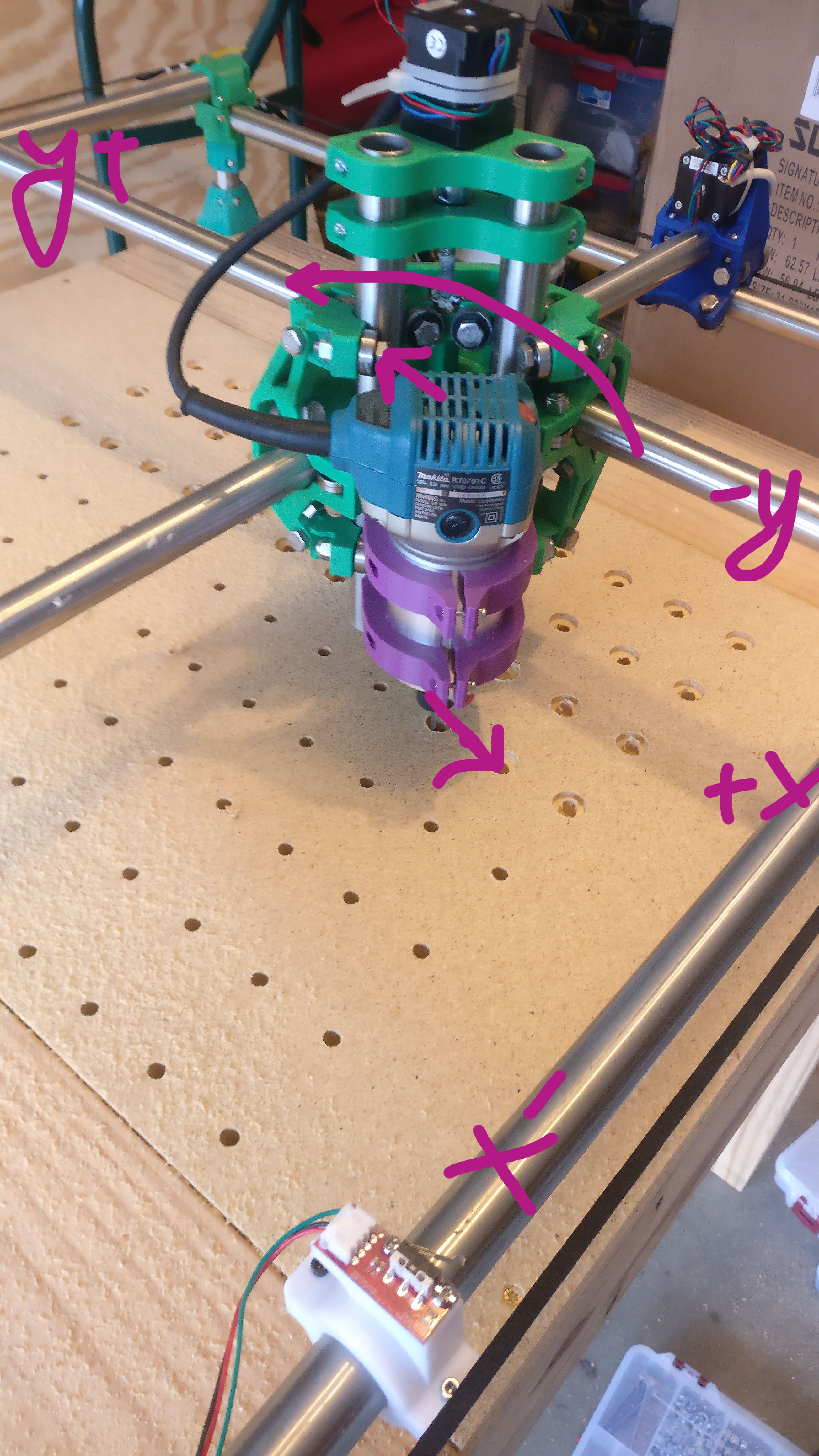
And all of them result in the spindle tilting upwards in the Y+ direction
Situations like this are incredibly frustrating I know, maybe you need to pause and take stock for a moment.
I’d look at it like this: if a tilt in the router is the cause of this, then run a small area with the problem intentionally made worse. Add a tilt to the spoilboard of 2/3mm over the whole bed in the direction you think is the problem. Does it make it much worse? Yes? Great, then a tilt in the opposite direction of the router will fix this. Then, look at the router and its mount: what will categorically move it in the right direction, with absolutely no doubt? Do something simple and practical like clamp a ruler to the side of the router/spindle pointing upwards, this will accentuate the tilt the cutter is experiencing. Run a taut line of string above it, note the position. Try an adjustment: is it moving? Good. Is it staying in the new position? Or springing back?
I don’t know if this is of any help at all, but when I have difficulties, I have to go back to absolute basics.
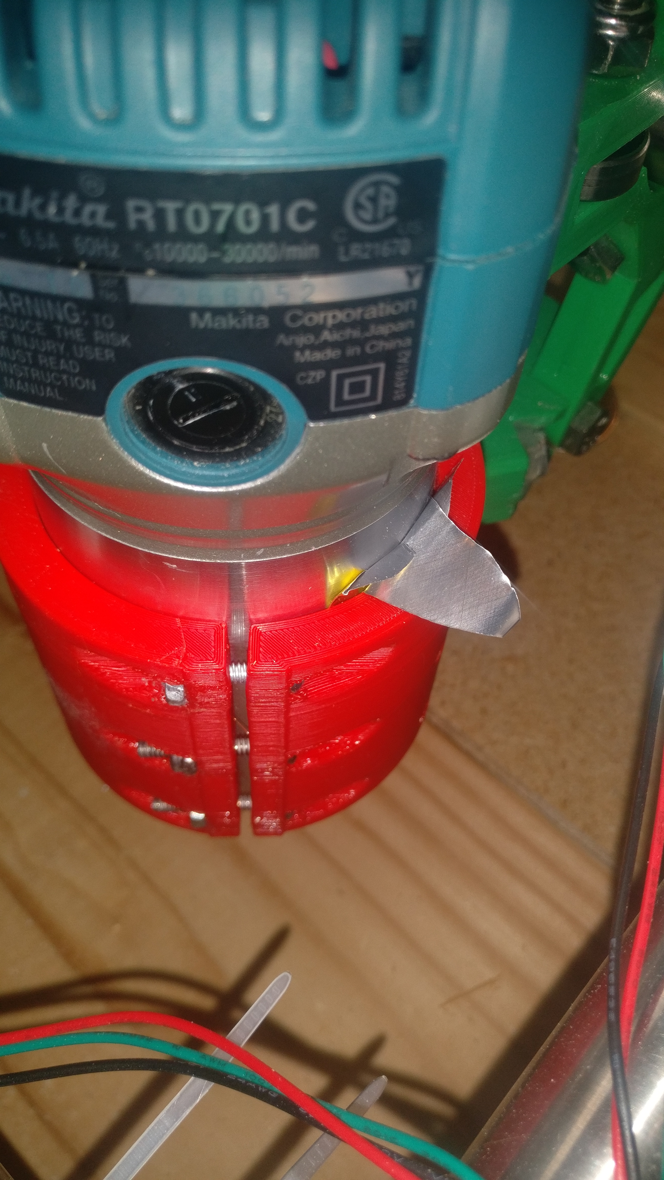
Can you post a photo of your tool mount, with an indication of which way it needs to move?
Ultimately, the tool mount is just a block of plastic you printed. Between shims, a file, a heat gun, or even reprinting, it can be any shape you want it to be. We just need to work out what we’re aiming for, then the best way to get there.
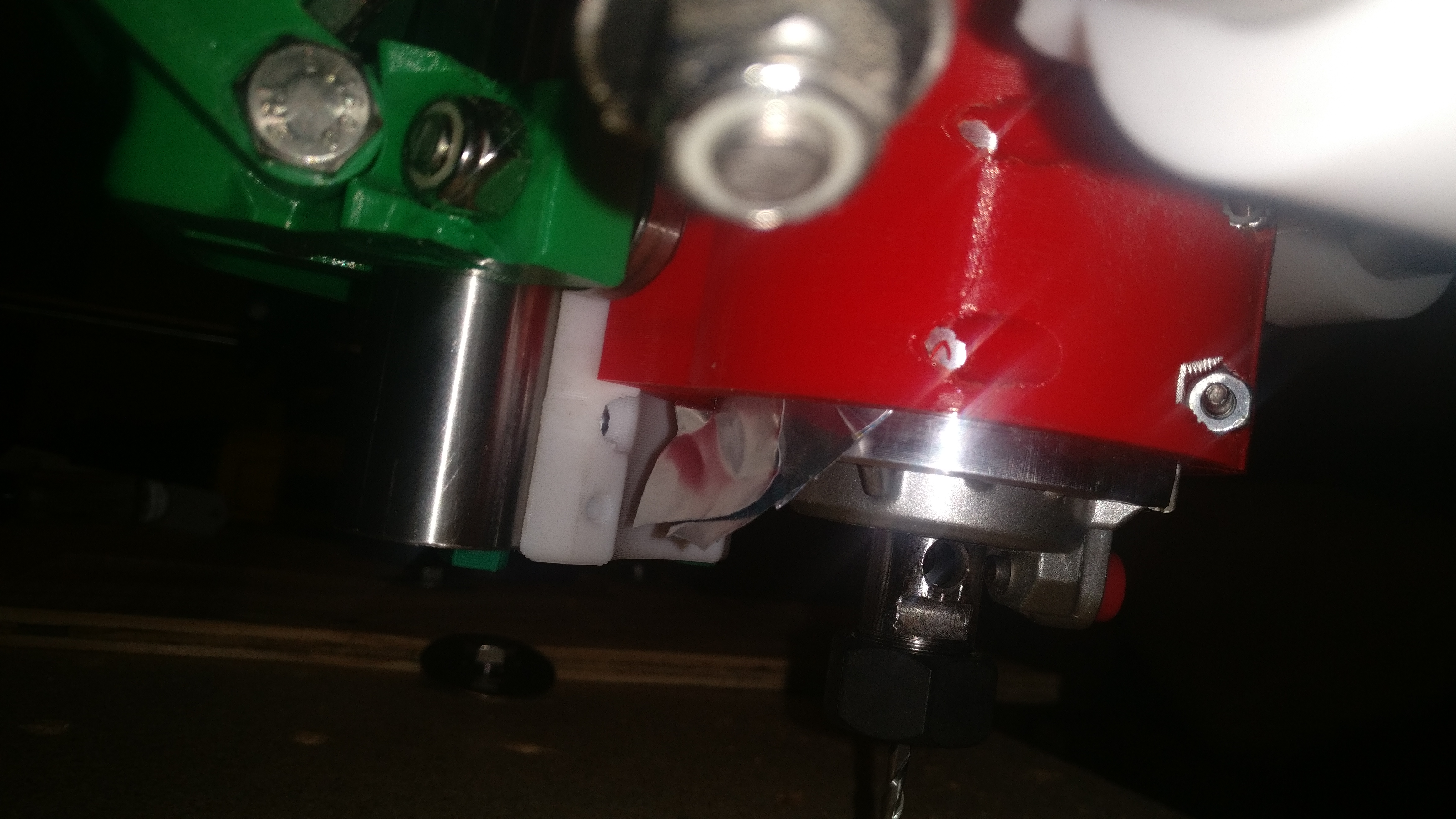
In that photo, where about are you adding your shim stock? I don’t use that tool mount as I have a DW660,
If I needed to to kick the bit of router towards the y- (so the top of the router would get closer to the y+) direction, I would place a small cut of soda can between the router casing and the tool mount that is directly inline with the Z rail that’s parallel to the Y axis.
FWIW, my router isn’t perfectly trammed either, and I gave up after adding two soda can thicknesses and few pieces of tape. I fought with it for a while as well. Most of what I produce needs a good sanding anyway, and that will take care of minor tramming issues.
I was adding the shim the bottom mount on the y+ side and on the top side on the Y- side. I think my end mill might be scalloped, so I will need to try a different end mill that isn’t all buggered up.
I’m surprised that didn’t work. I can’t see any reason why the mount wouldn’t response to that. Did you try a tramming tool?
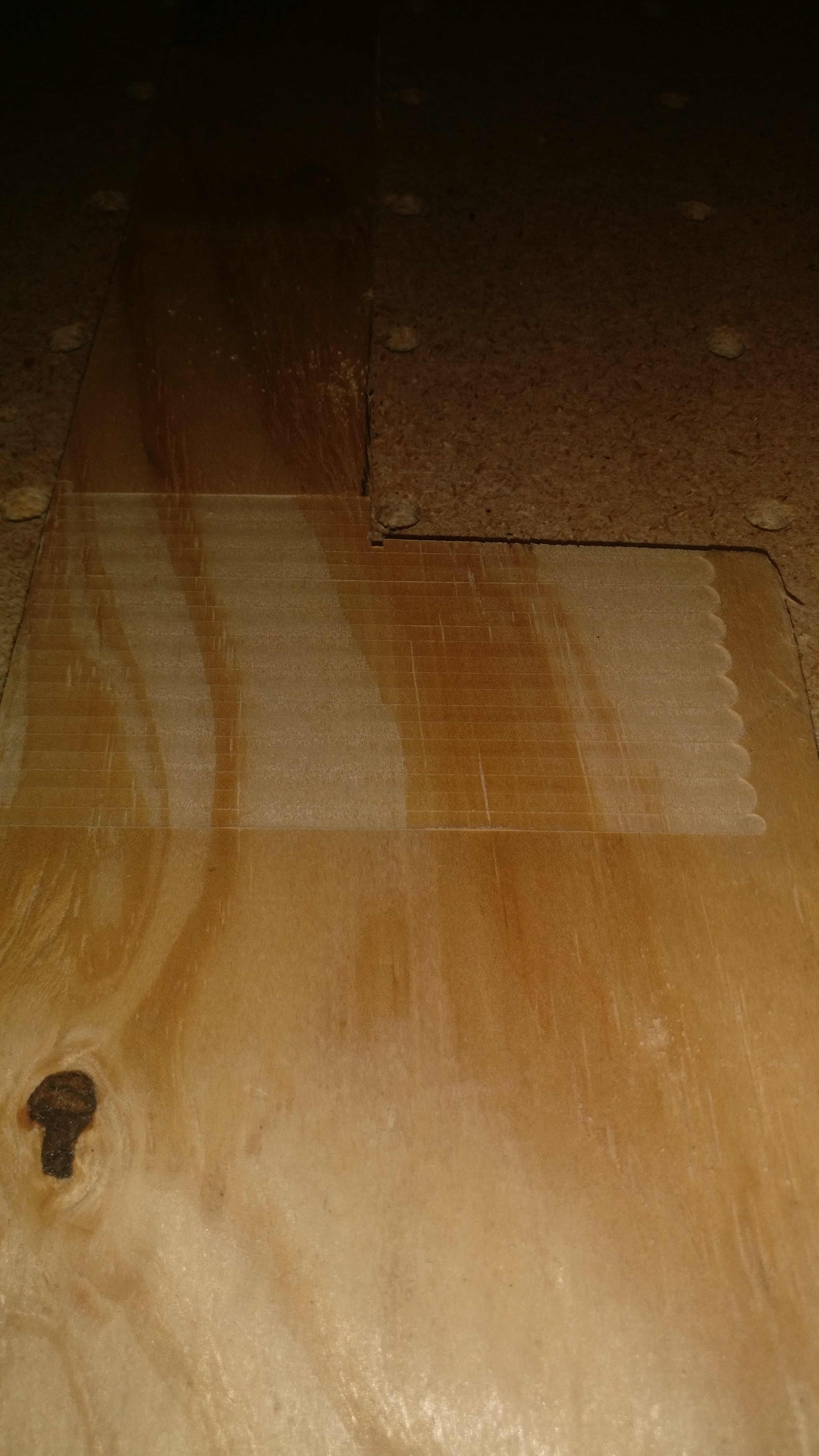
Actually, it might not be tramming (that’s just something you should check before moving on). The other thing it could be is the router bit being pushed slightly out of plumb. You mention that you suspected your feeds and speeds, but it could also be too much step-over.
If you surface in a back-and-forth motion, the bit is pulled in a y+ direction on one pass, then y- when it goes back the other way. If the tool sticks out a long way, or the Z axis twists, the cut will be uneven.
Try pushing on the bit with the steppers engaged (and the router unplugged) to see what moves. I discovered a loose roller on my machine. If there’s nothing loose, try half as much step over and/or peeling rather than linear cutting.
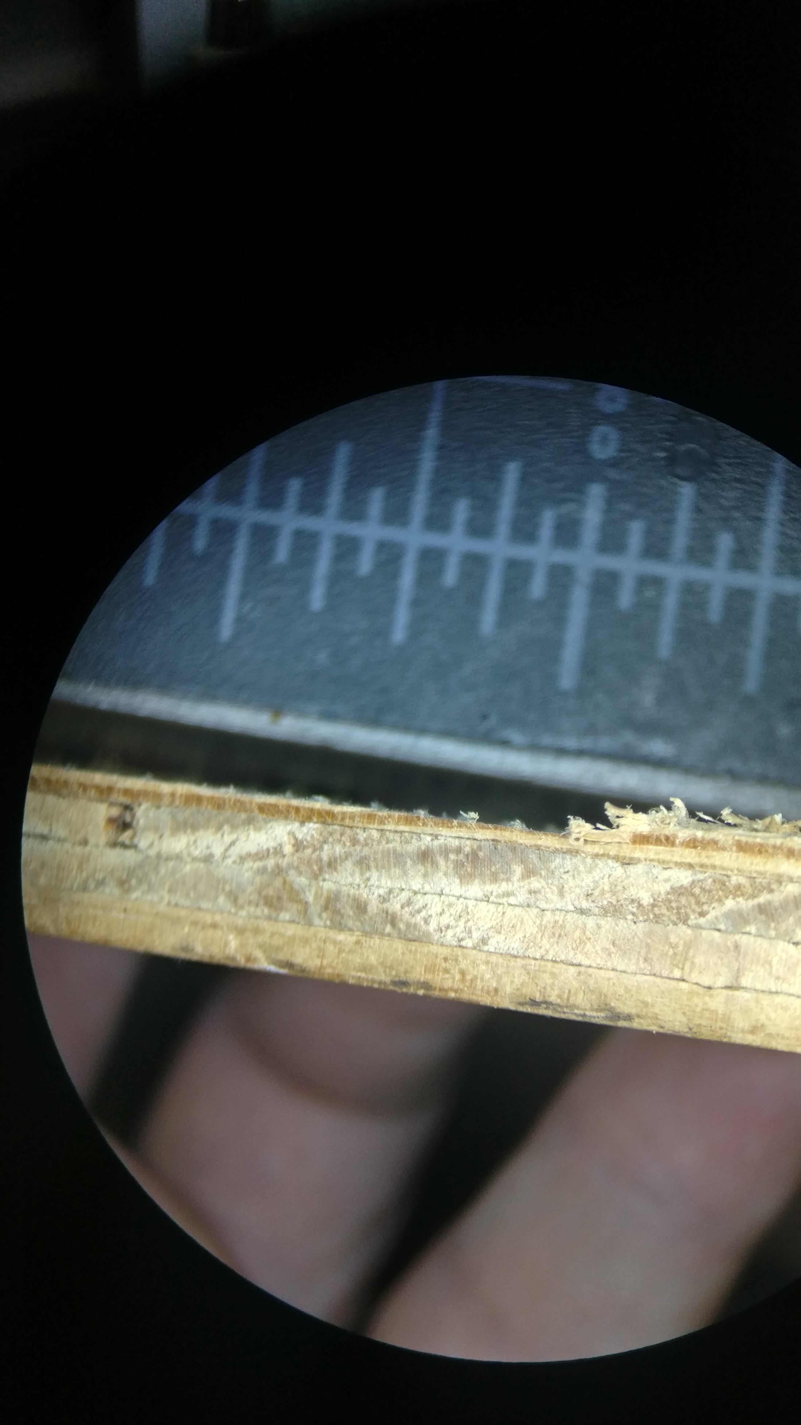
The surface is definitely better with the shim and a new endmill, but there is still an angle I can’t resolve with shimming, no matter how much I try. I’ve tried using a tramming tool but it seems the angle is too much to shim out?
Edit:
I would think that if it was a flexing issue it would be different in one direction of cut versus another?
To my eye, that looks like a heavy router with not much holding it in. I suspect it is pulling itself down and away from the gantry. That is a complaint without a solution, but maybe you can figure something out.
Yep just waiting on amazon to deliver one since I can’t seem to find one at Lowes or Homedepot.
I’ve tried printing a new mount and a new universal mount as maybe that was the issue, but it was still at the same angle, so I decided to try A LOT more shims.