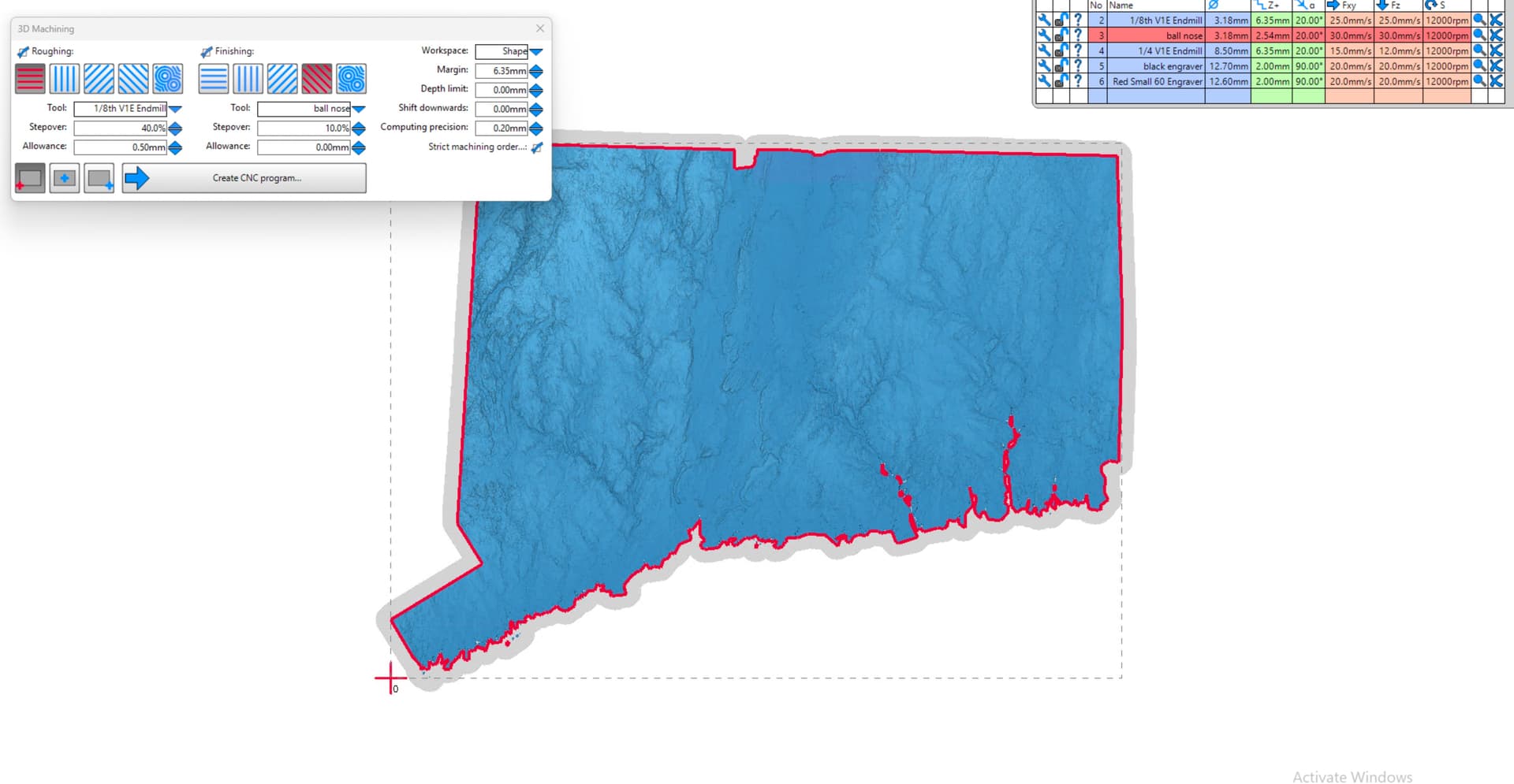
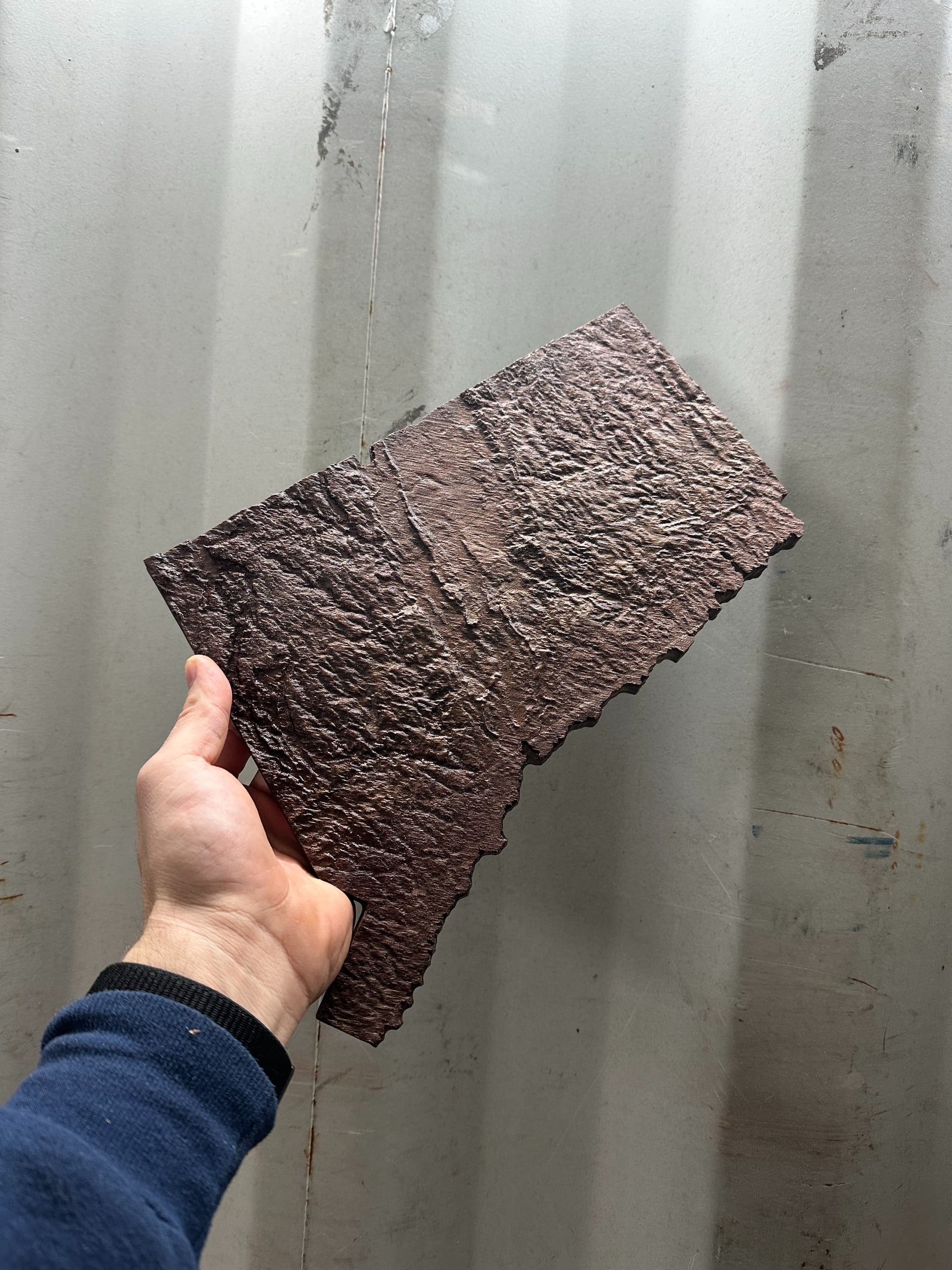
Imported a 3d stl of the state of CT into Estlcam. Estlcam v12. It generated a pretty great toolpath and the part came out pretty amazing. But I ran into a snag and had to do a workaround. I plan on doing some more of these so I’m wondering what the issue may be.
This is the 3d model imported, just for reference.
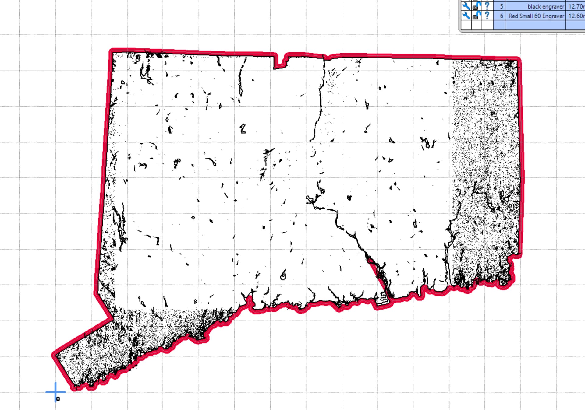
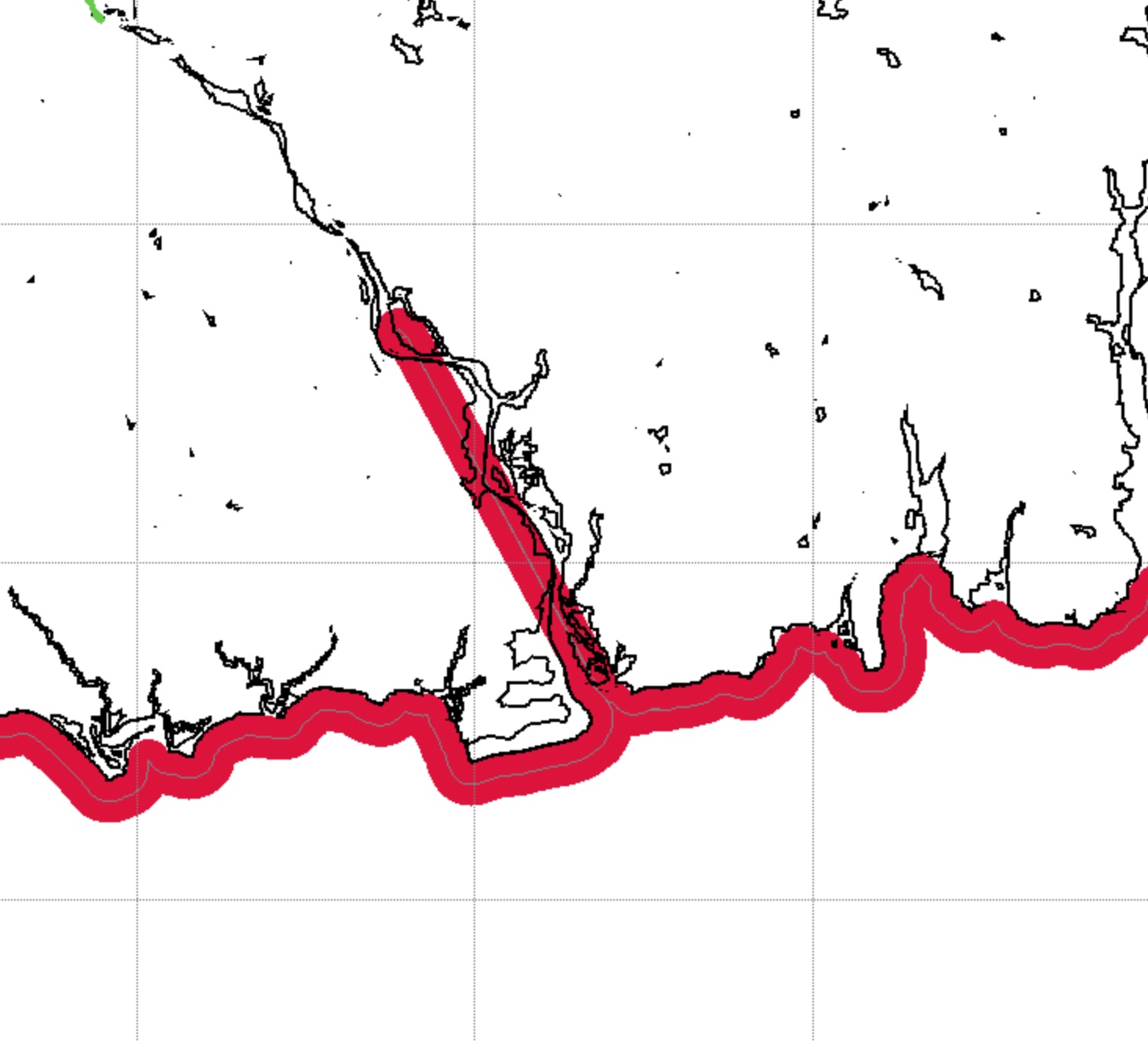
I then converted it to a 2d image to get the part outline to cut the piece out. But if you see down at the bottom kind of in the middle the cut path just goes straight into the part.
I ended up changing the bit to a 1/4in bit which avoided that path altogether.
Its not my STL file. I downloaded it online but it seemed to be a pretty good file. Is there a better way to get a cut out of a 3d model in Estlcam? Did I miss a step? Worked out in the end but if there’s a better way I’m all ears.
I could, I’ve never done that and didn’t try it. I will practice on a less complicated shape. I don’t know how much “snapping” Estlcam does. Down at the bottom of the state there would be a ton of points to click.
I just thought it odd because it basically just goes in at a straight line and disregards any actual contour in that section.
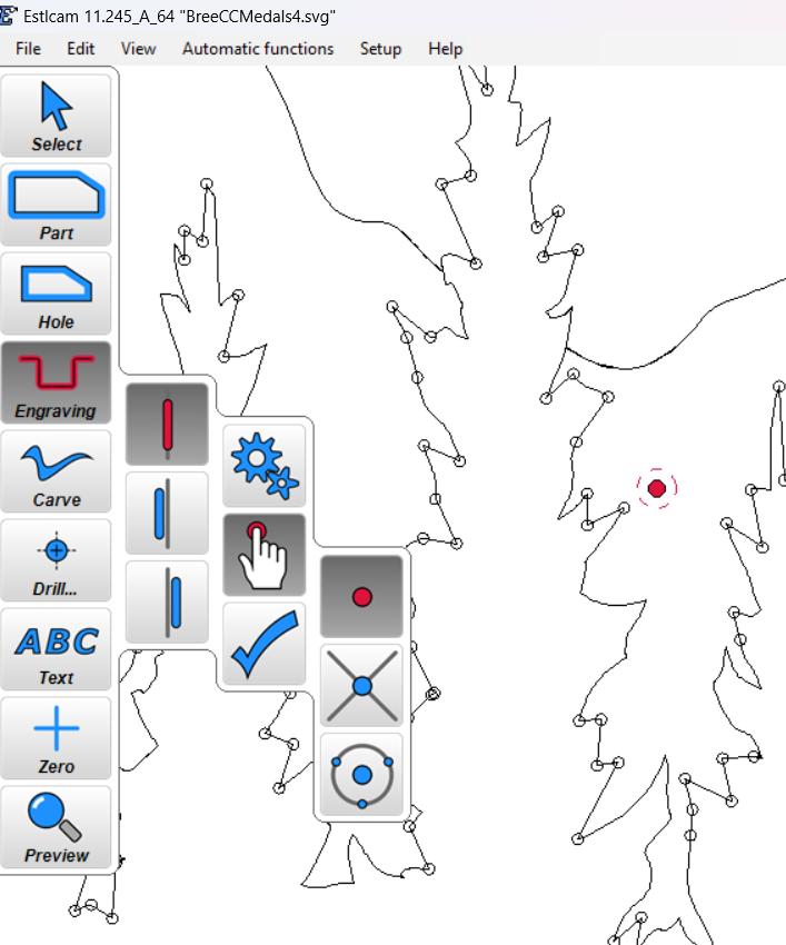
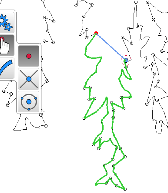
then right click and it will fill the outside lines with dots and turn gray (if you normal click it will straight line to your pointer (DON’t do normal click this unless your green line doesn’t go where you want it to then you can force it a small distance and go back to right clicking).
I’m not an expert (far from it), but it seems like you are asking EstlCAM to cut a 1/16" (or narrower) Part path with a 1/8" bit. That’s a bit like trying to drive in a finishing nail with a 5 pound mallet.
I’m thinking that if you used a 1/16" bit instead, the Part command would probably have better results in following the narrow path.
A 30 Degree V-Bit might also work, but you would probably need to use the Carve path instead of the Part path, and I’m not sure how that would work on a 2D drawing. But I’m REALLY not an expert on the Carve function, so take that with a couple of pounds of salt.
yea, your comment is right. the cut that goes into that inlet doesn’t follow any of the contours, so it should block it regardless because the inlet is too small for the bit. This may be a bug in estlcam, but likely a problem with the svg.
In corel draw, I would take the svg and highlight the whole thing, do an outline as new object for the outer border, drop just that outline into a new page and look for any anomolies and modify it there and then export/import it as an updated background into estlcam with the carve outline in place to make sure the home position is correct with your other cuts, then delete this cut and redo that step for the final outline.
normally what will/can cause that in a file is an open path , which will happen when tracing an image file , depending on what other software you using eg lightburn highlight area and click close path
Is that out of bounds path still visible when you use the Preview tool? I haven’t seen it in v12, but v11 had some buggy visuals that didn’t make it to the Preview or G-code.
It’s interesting in that the gap appears to be pretty darn close to tool diameter wide and that there is a lot going on just inside the opening. Is the issue still there when using a smaller tool or after adding a Finishing allowance to the 1/8" tool path?
The v12 manual shape detection tool mouse clicks are the opposite of the v11 tool, left click to follow the green line and right to ignore it. You should be able to manually set that Part perimeter with a handful of clicks (assuming you only need to jump across that one gap). See also:
It was still visible. I specially checked that. It was driving straight into the part. I’m guessing a 1/16th bit would have done better. It just surprised me that it tried to cut in there at all as the 1/4” ignored it as expected.
I’m chalking it up to a bug or something like an open path like @Terry_O_Sullivan said.
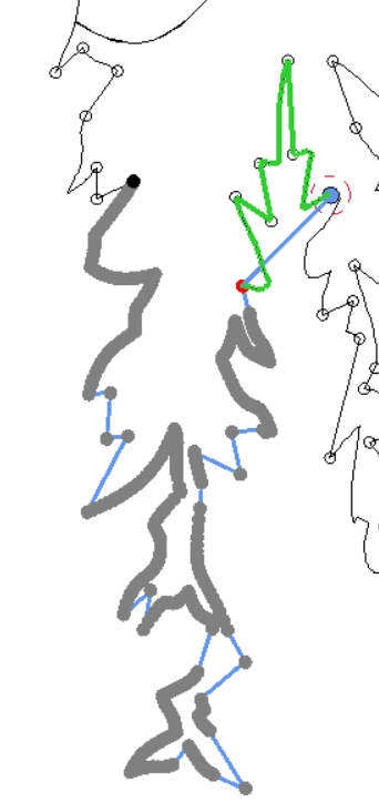
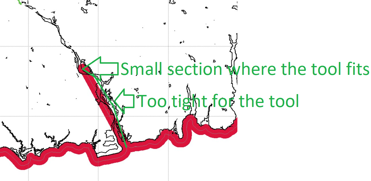
the issue is that the shape has a very tight section where the tool cannot fit.
Usually those areas are removed - but in this case there is a small inner section where the tool fits again and causes the toolpath to take the shortest possible way to connect both valid areas.
You need to use manual shape detection and skip the river so the shape does not follow it along to the wider lake. Or use a much smaller tool that also fits the narrow river.
just another thing: maybe try the carve feature with a pointy tool for things like this.
Carves are much better suited for art projects as they can handle all the small details.
But the drawing quality needs to be good in the sense that there are no unintended gaps and especially no line ends crossing each other as this would cause the carve to “spill over” to the other side.
Estlcam handled the 3d portion of it beautifully! At this stage I was only trying to get a “part” cut out of the piece. That might be a cool thing to add in a future release? Or maybe its already there and I don’t know. But after importing a STL, you have the roughing pass, finishing pass, then maybe an option for a part cut.
Either way Estlcam did better on this than any of the others by a landslide! I’m thrilled I got this far!
Thanks for sharing your journey. 3d Carving is on my list. I’m getting pocketing and 2d Carving for raised lettering down first. I have found foam to be most accommodating. Your state cutout is very similar to what I want to do.