Hey, is the bottle holder available anywhere, and have you adapted for V4 yet?
I can provide the file if you want, but it would need to be remixed for use on the LR3, as it is designed much wider than the standard strut dimension (normal LR3 strut braces are 15mm wide, mine are 21 mm wide). PM me if you really want it, and let me know what format (f3d, step, skp etc) you want it in. However…
No, and no plans to do so. I am quite happy with this machine as is, and don’t see any burning need to abandon it for the latest and greatest.
Note that the bottle holder would need to be seriously remixed, as the LR4 doesn’t have the same strut brace profile or any mounting holes at the rear. You are probably better just starting from scratch and designing your own to suit your purpose. Or you could design one to sit on the lower strut itself, as the back of the gantry is open.
1 Like
Yowza!!! That’s one large crown you have ![]()
2 Likes
Go big, or go home!!!
(or in my case, go big, and stay home…) ![]()
4 Likes
Even with it right there and obvious, I couldn’t see that till pointed out.
Well, after visiting the V1E Forum daily for almost two years straight (except during a couple week long vacations that prevented me from getting the 365 consecutive days badge), I took a few months away from the forum, and from the hobby, to focus on other parts of my life. But now that I’ve caught up on a lot of things that needed attention, I think that I’m finally ready to get Big Red back in operation!
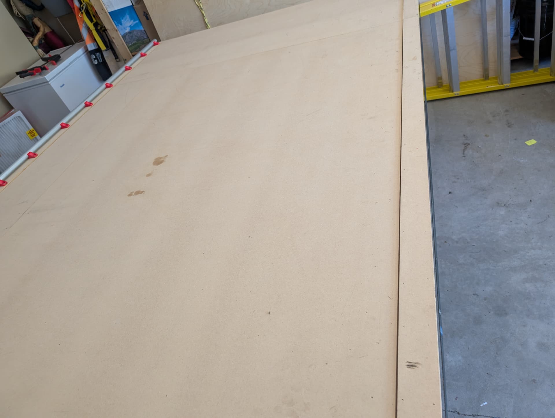
First thing was to install a spoil board over top of the surfaced 3/4" plywood base. I used 3/8" MDF. and added a strip of the same along the rail and roller surfaces to maintain the same Z distances .
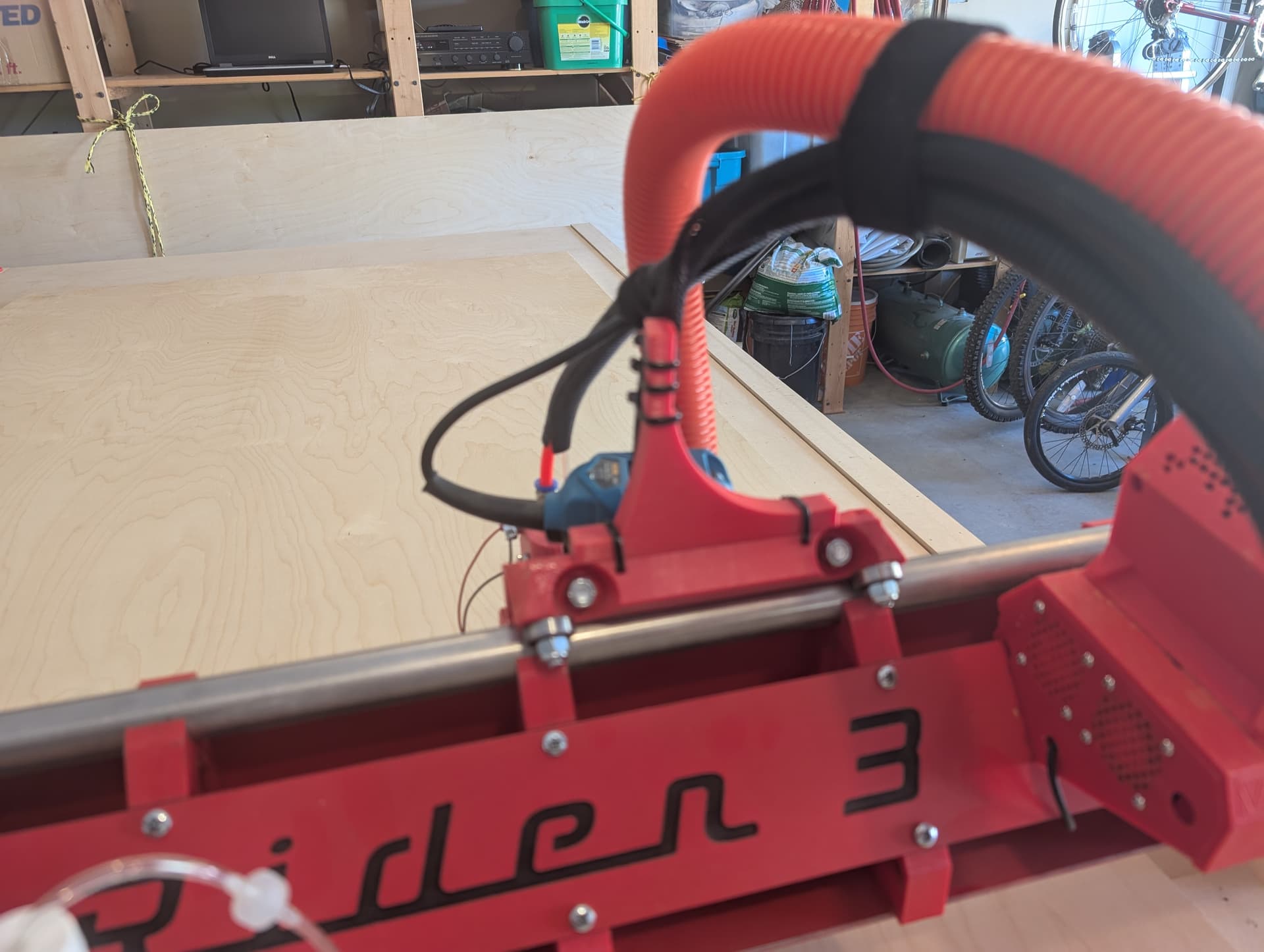
After getting the table all set up and ready to go, I had to put it away again so that I could get enough space in the garage to do an oil change and brake check on one of the cars. Rather than remove the gantry from the table, I found a way to keep the gantry attached while I tilted the table out of the way. It involved using a couple of clamps to hold some wood against the roller side, and using a bungee cord to hold the rail side in place against the rail…
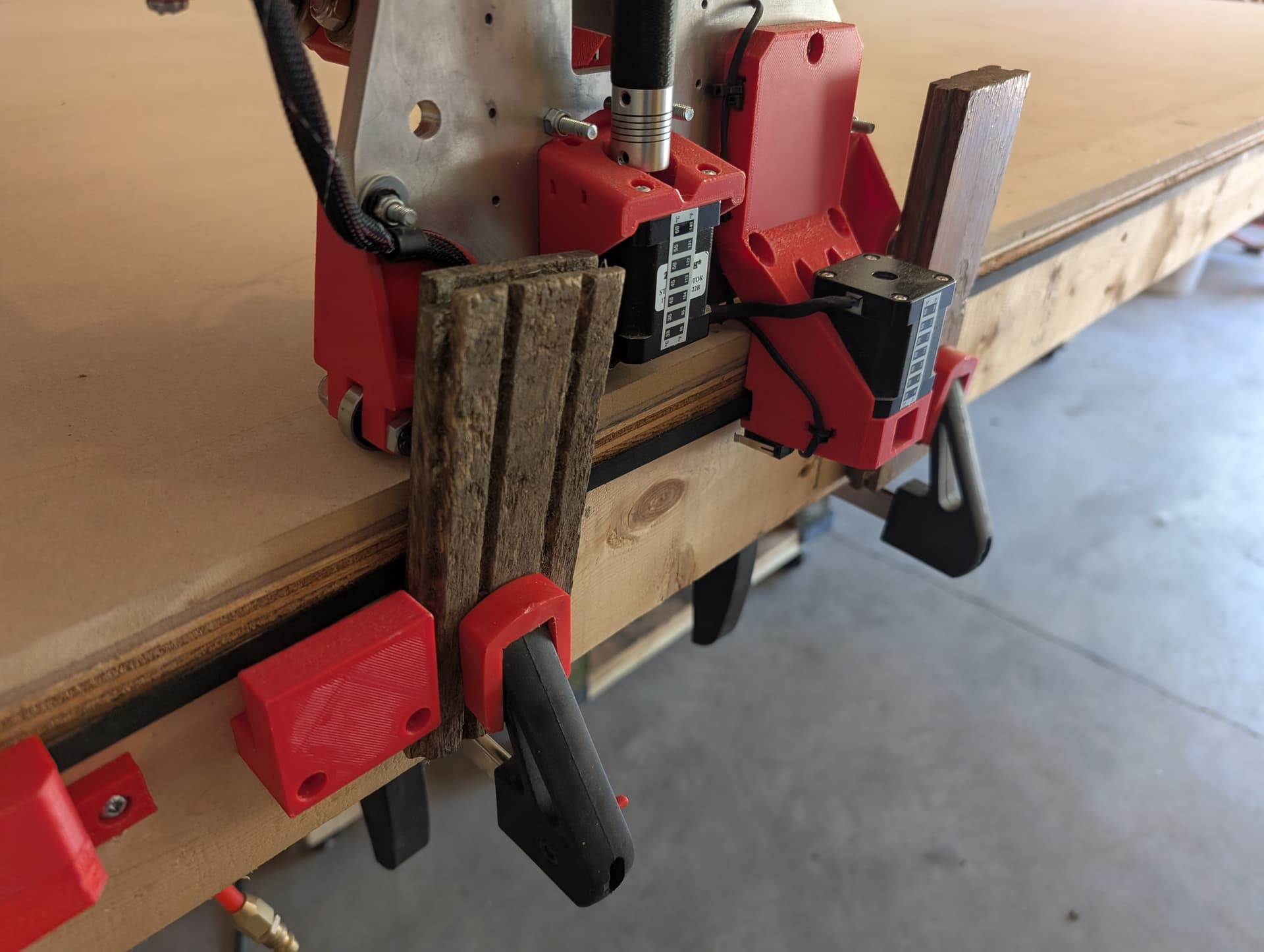
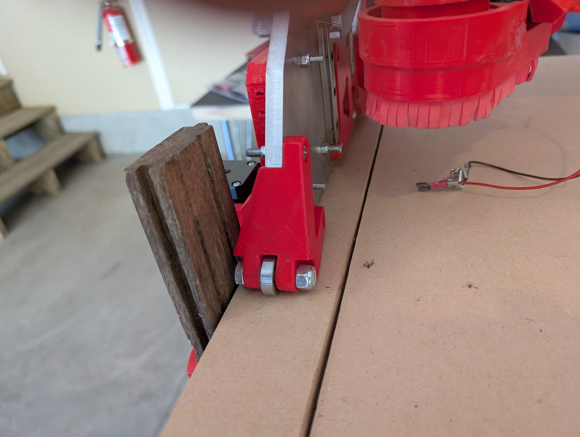
It worked great! I was able to fully tilt the table out of the way while keeping the gantry in place.

7 Likes
I’m going to be cutting a couple of sheets of 3/4" plywood to make a custom poker table. There will be some holes that need to be very precise, both in diameter and in placement. so I’m going to do a few test holes for calibration purposes before attempting the final cuts
2 Likes
would be nice if the lr could cut in the folded position. (just dreaming)
The in-development experiment we call MPR&P works upside down… I bet it would also work at any other angle too.
2 Likes
It should, that looks like the onefinity cnc. But i dont see it being 4x8
Sadly one of the by-products of me being away from the Forum for a while is the loss of access to the Lounge. As such, I’m not sure what MPR&P is all about…
2 Likes
Don’t worry. Nothing secret is happening in the lounge.
3 Likes
Maybe not, but there was always some interesting stuff happening there! I’ll have to get back into some serious post reading and start giving out some likes to get back to Regular status.
4 Likes
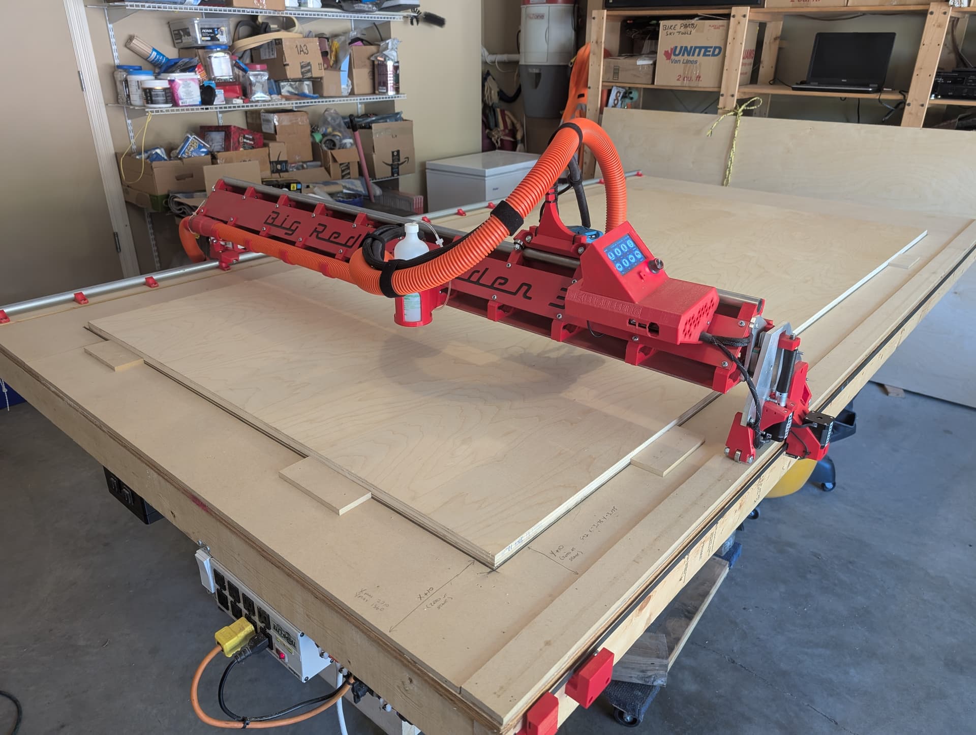
Ok, I’ve done some last minute tinkering in preparation to actually start using the machine to cut something other than parts of itself.
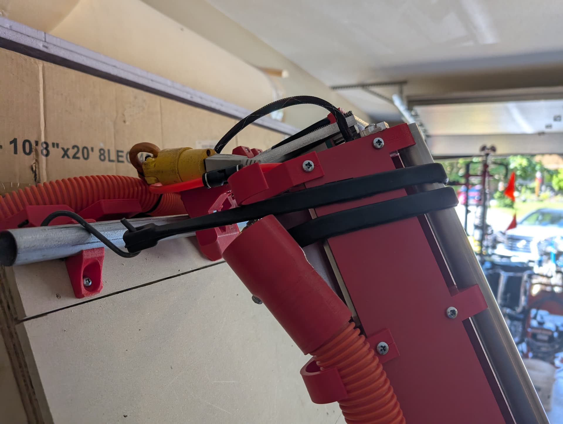
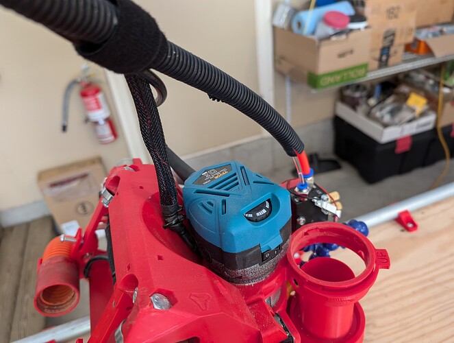
First up, I found that the stiff wire in the vacuum hose support rod (see post #8 & 18) wasn’t holding the weight of the vacuum hose/cables, and that the vacuum hose was sometimes catching on the controller box. So I designed and 3D printed a bracket that attaches to the top of the core with tie-wraps and supports the stiff wire, keeping the hose away from the controller box.
Before:
After:
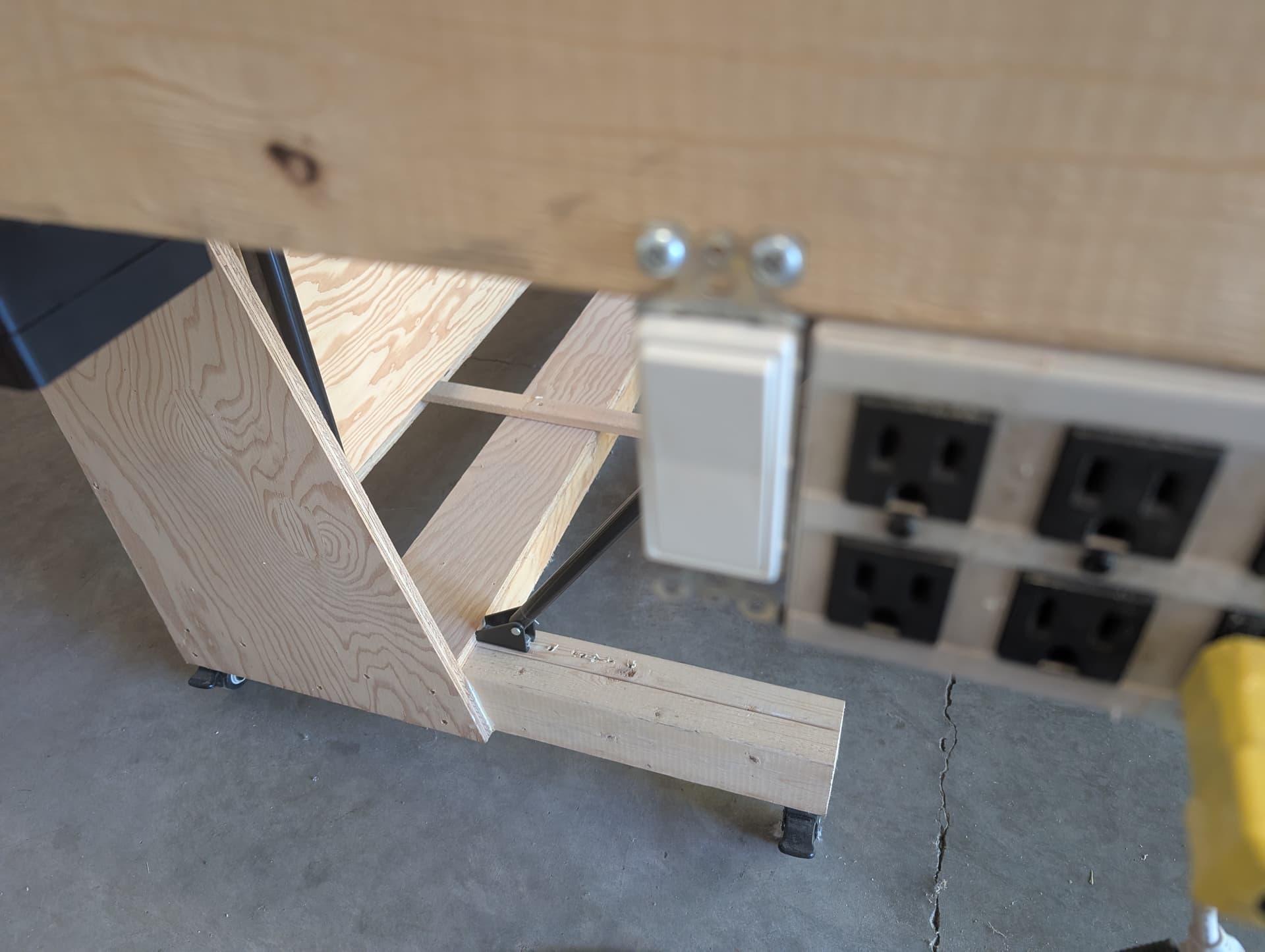
Next up, I am using my built in vacuum for dust collection. I had to walk over to the vacuum and turn it on or off at the start and finish of every cut (and whenever I paused the cut). I needed a way to have the on/off switch closer, so I connected a length of wire to the vacuum, and placed a switch close to the rest of the CNC controls.
I wanted to have a way to quickly place a sheet of plywood in the correct position for cutting. I also wanted to place the sheet so that I could cut all the way to the edge of the sheet. Starting at X0 Y0 after homing wouldn’t allow the machine to move into negative territory, instead the machine would either hit up against the end stops causing skipped steps, or just not move into negative numbers.
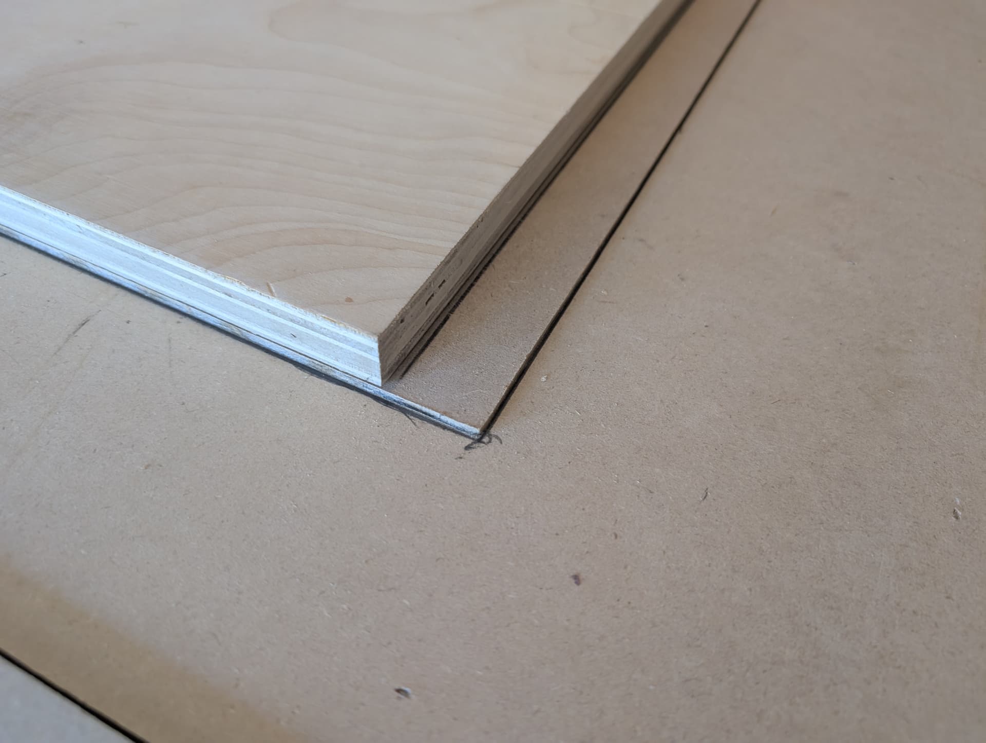
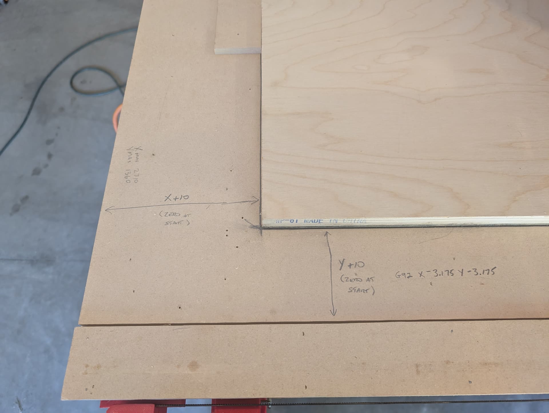
I moved the machine to a position of X10 Y10 after homing with a 1/4" bit, and then placed a sheet of 1/8" MDF and a sheet of plywood on the table. Moving the machine along both the X axis (Y=10) and Y axis (X=10), I aligned the sheets so that they were just making contact with the cutting edge of the bit at all points. I then made a pencil mark along all of the edges so that I could visually verify that the sheets were aligned properly. I also installed some short sections of 3/8" MDF to use as alignment stops so that I could quickly and easily place sheets into the correct position.
Now I simply push the sheets against the stops, and then visually check the sheets against the pencil marks. After homing X & Y, I move to X10 Y10 and then issue a G92 X-3.175 Y-3.175 command, and I’m ready to cut right up to the edge of the sheet.
6 Likes
Thanks for sharing your approach. I really need to put a stop on mine too.
2 Likes
Major Milestone Achieved!!!
I first started this journey in July 2023.
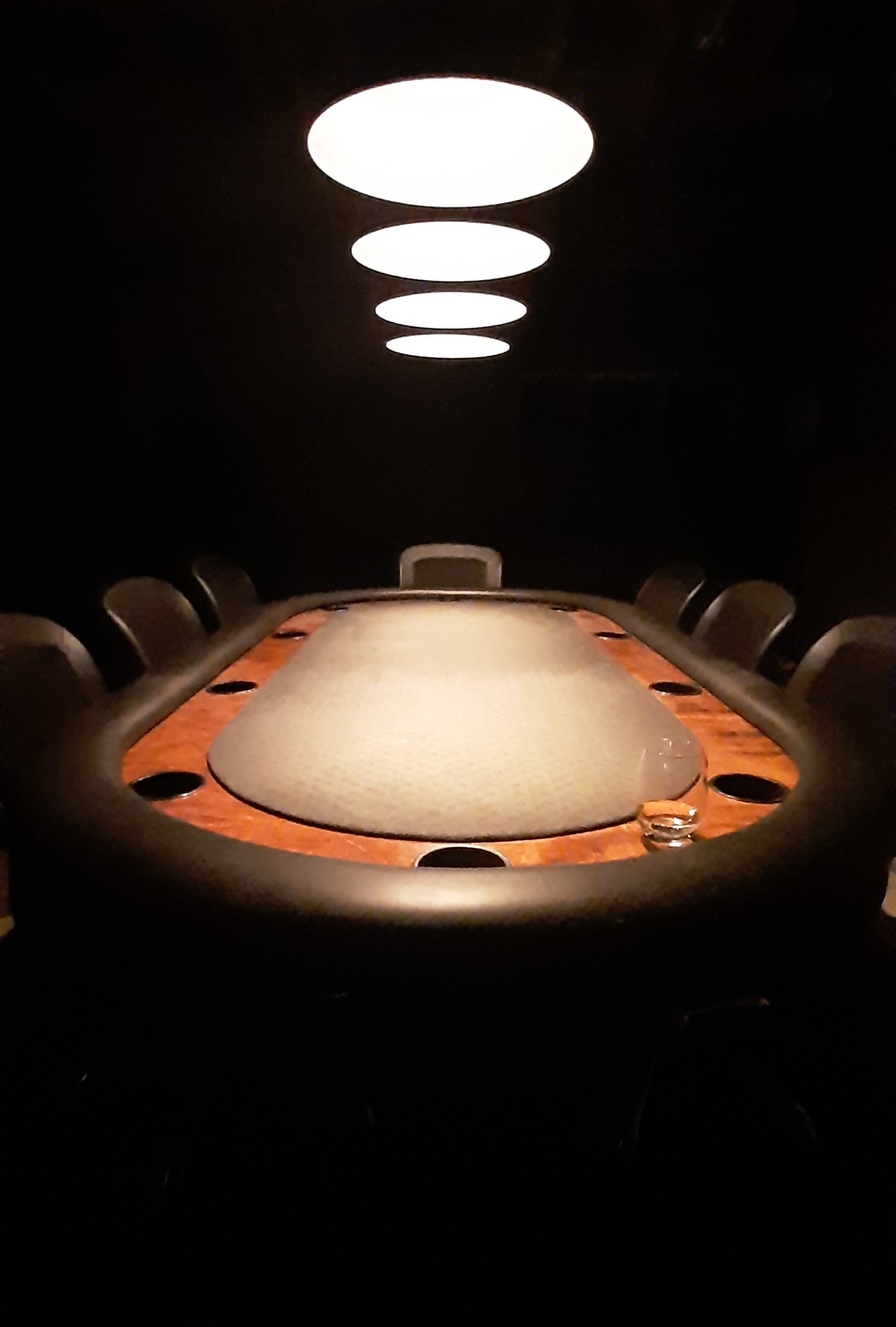
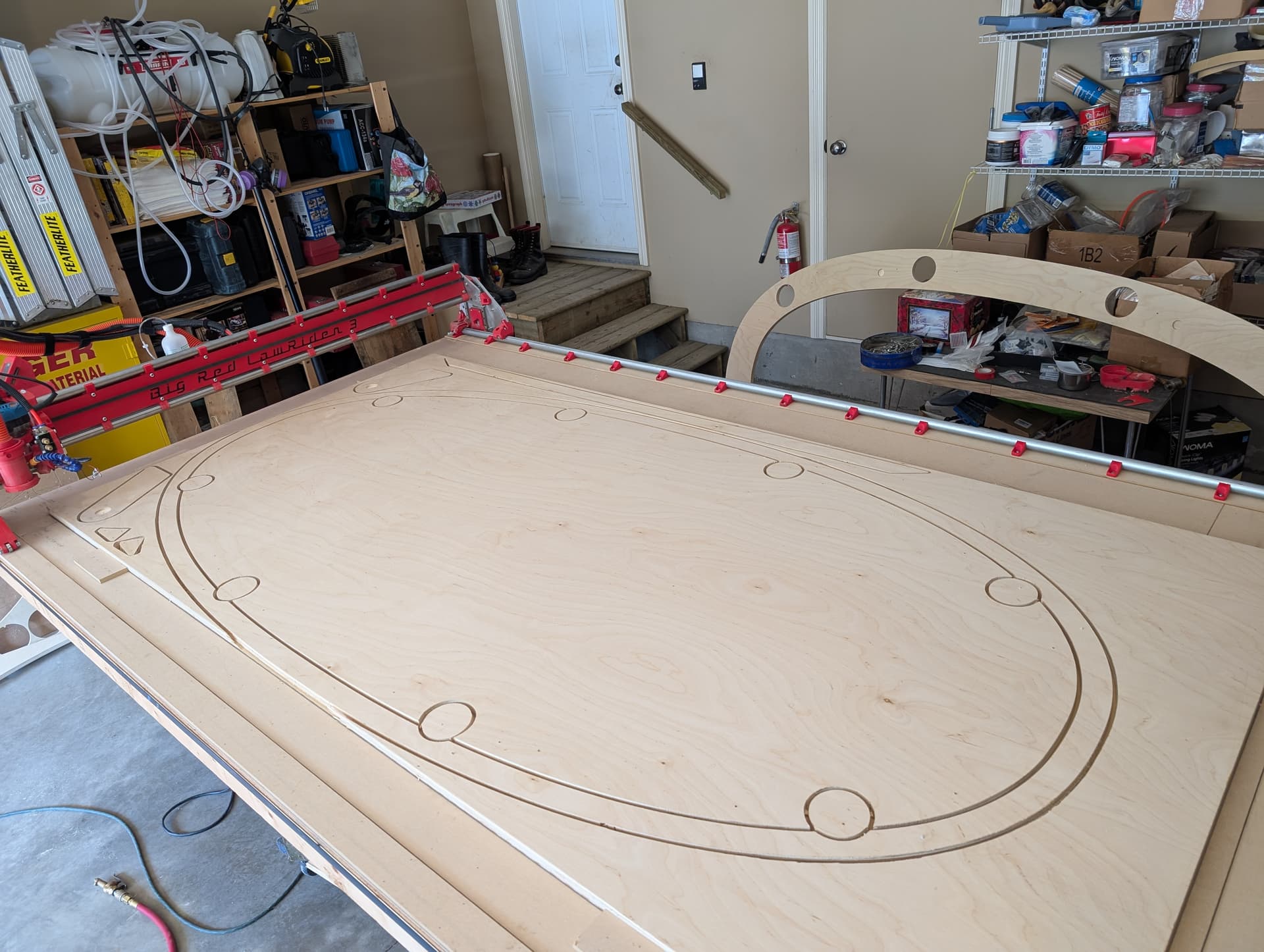
The reason that I decided to build a CNC was that I wanted to build a custom shaped poker table, and I needed a CNC machine to cut the complex super-ellipse (aka Lame curve) shape that I wanted to use.
For those unfamiliar with a super-ellipse, it is based on a mathematical formula where any point on the curve is defined by

or

It’s too complicated to draw by hand, and I wanted to be able to play around with different parameters. Changing “n” changes the shape of the table, changing “a” (length) and “b” (width) changes the size of the table. So I pretty much had to use a CAD program to create the curve before I could cut it with the CNC.
Along the way, I had to teach myself all about 3D printing, 3D modelling in CAD (first in FreeCAD, then in Fusion), CAM/G-Code, creating Youtube videos, and everything about building and operating the Lowrider 3.
Well finally, over two years later, I have completed cutting the first full sheet of plywood for the poker table (sheet 1 of 2). Woohoo!!!
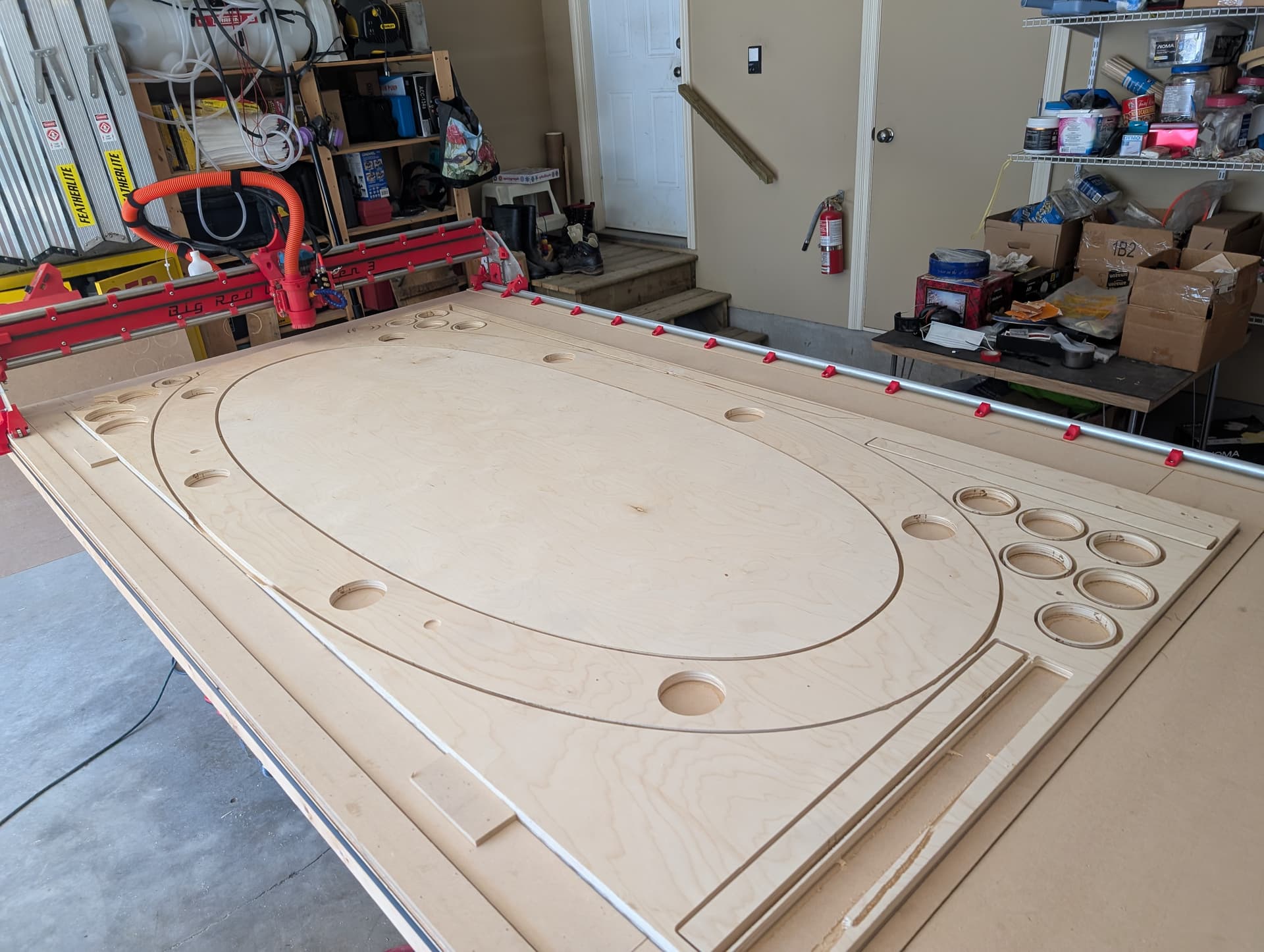
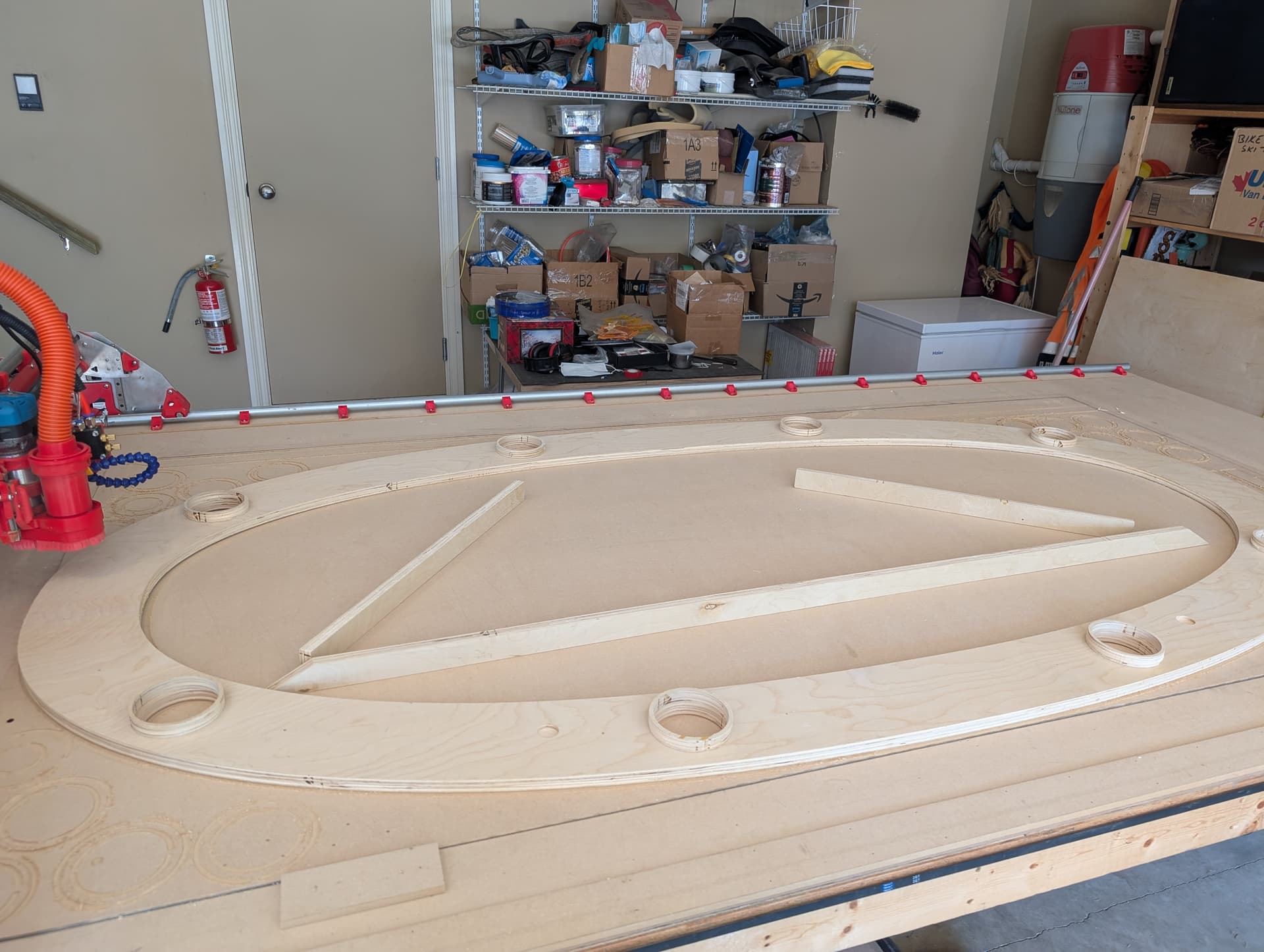
There were a few hiccups during the cut, mostly self inflicted. I had secured the plywood to the spoil board with small nails at three locations along the end edges. When I cut the large curved part, it cut the edge in two places, and when I went to do some later cuts in those sections, they were only held by one nail, so the board twisted and the bit dug into the plywood.
I also had an issue where the X motor started chattering, and another where the Z1 motor would lose power during a cut and the Z1 homing switch was open circuited. I traced the issue to a couple of extension cable connections that I hadn’t used an S-Bend on. I had to open up my cable management, pull some slack from inside the controller box, and lengthen the cables enough to get the S-Bend on each connector and tape it all back up. It seems to have fixed the problem (hopefully).
I have one more sheet to cut (hopefully tomorrow), and then I can actually start building the table. I’ll post photos as the table construction progresses.
13 Likes
Woo hoo… Finally!
Congratulations on getting nearly there, and on your machine build.
I can’t wait to see your poker table get fully assembled.
I bet you’re really stoked to see it all coming together.
3 Likes
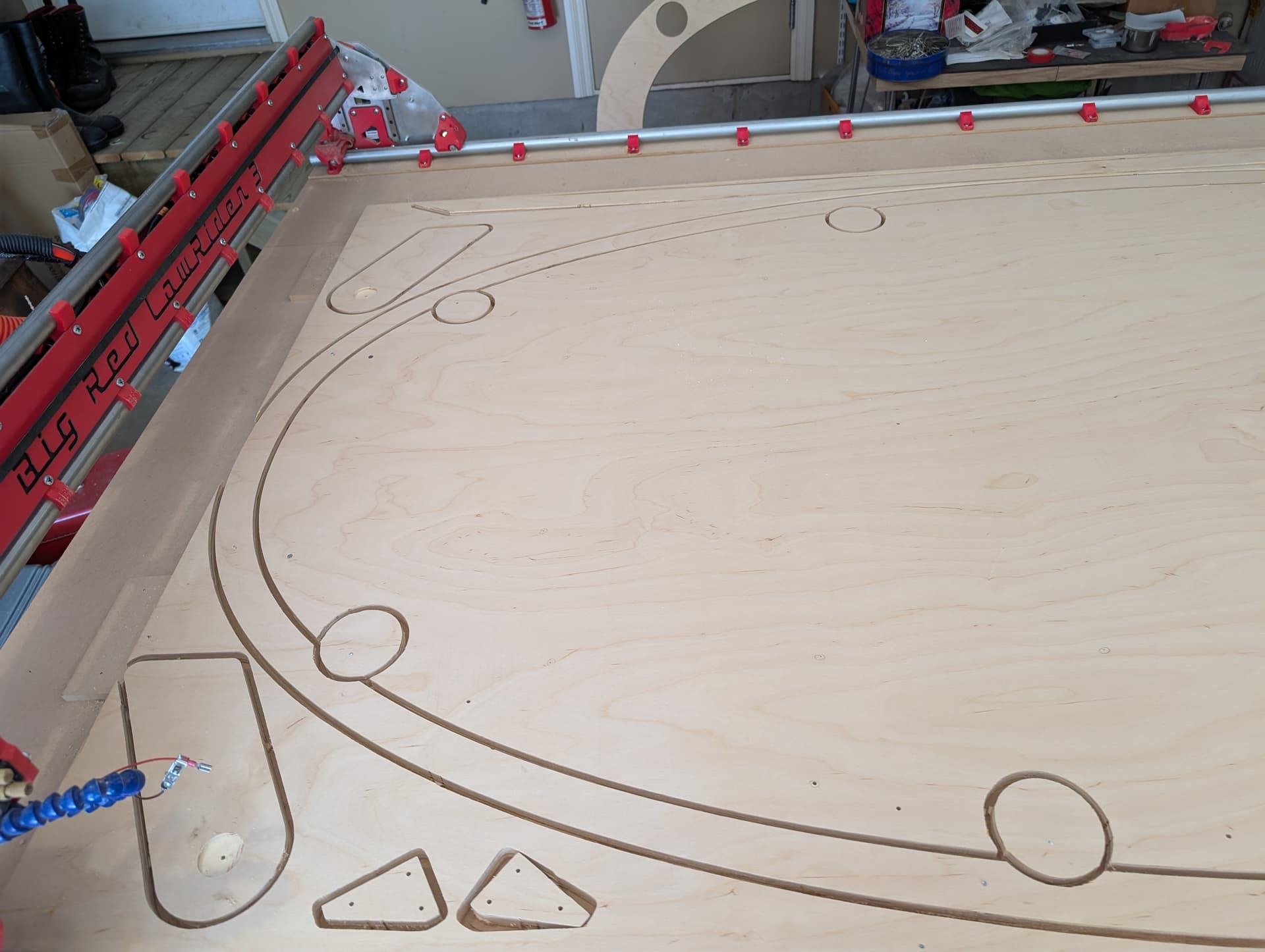
Two years to cut the first sheet, less than 24 hours to cut the second sheet. We’re in a groove! Too bad that I only need to cut 2 sheets for this project, I’m just starting to get the hang of things.
I need to clean the parts up just a bit (trim the tabs with an Exacto knife, fill some of the hold down nail holes with wood putty, etc.), and it’s on to assembling the table.
Fabricating the padded rail is the most challenging. I start by gluing and brad nailing the upper rail (wide curved part from yesterday’s cuts) and the lower rail (narrow curved part from today’s cuts) together. Then I glue all of the cup holder rings to the top surface of the upper rail.
Next I use spray adhesive to secure 1” foam to the top and sides of the upper rail, (cutting out the cup holder holes in the foam at the same time), and then stretching and stapling the vinyl over everything. I’m told that it can take almost 1000 staples to do the job right, so a pneumatic stapler is a must!
Pictures to follow over the next week or so…
6 Likes