Scrounge/Marion,
Please recognize that the simple 2-board interface I’ve presented here isn’t the conventional way these boards – particularly the CNC shield w/o the Uno – are used. This was simply an idea I had for an inexpensive LinuxCNC interface – an ORIGINAL IDEA/CONCEPT – and you won’t find this particular wiring scheme and board combo anywhere else on the internet. You’re only going to confuse yourself going off and watching videos of these same components used as they NORMALLY are used.
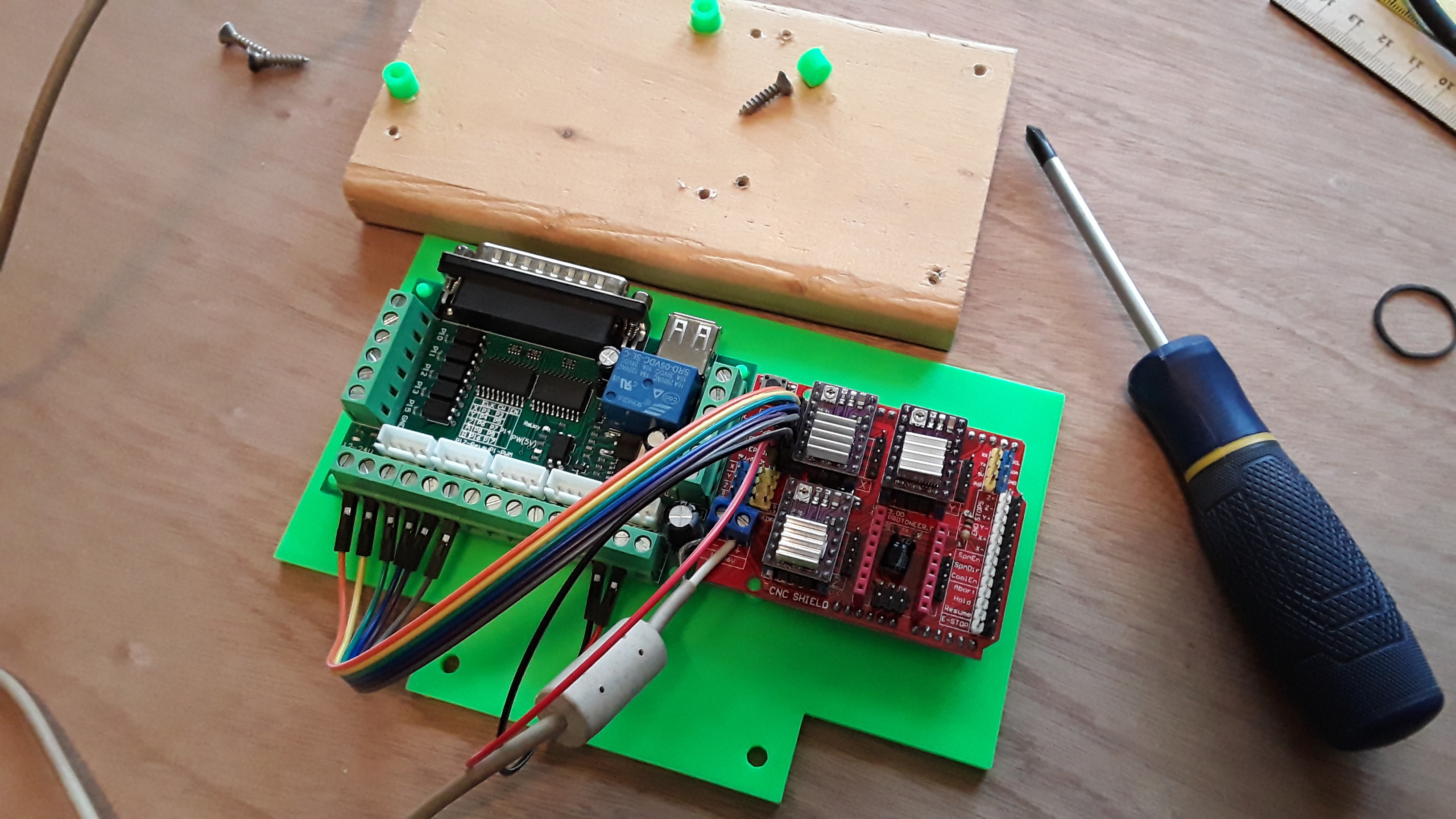
Again, I’m not using the CNC shield as it is normally used… on purpose. I use the CNC shield WITHOUT the UNO (don’t need it… that’s what LinuxCNC is doing)… and the shield basically is just a way to conveniently mount and hook up the step-stick motor drivers. I could have used a prototyping board, a solderless breadboard, or other… but I would have basically had to wire all the connections just like what’s on the CNC shield already… so I used it instead. Please note that there are no active components on that shield (other than the drivers)… it’s just wiring, sockets, pins, a couple of screw terminals, and a reset button. There’s nothing magical about it. But it’s just very logically laid out, provides convenient pins for all the required signals, and was almost perfect for what I needed.
So you know what signals come out of BOB and you know what pins have that same function on the shield. It’s a simple matter, then, of hooking the corresponding signals together… X-step and X-direction to the shield’s X-step and X-direction… Y, same… and Z, same. All these signals are grouped together… in the upper-left corner of the shield as shown here

Use a board jumper to connect the EN/GND pins (a common enable for all the drivers), and then jumper wire the corresponding BOB signals to the shield’s step/dir pins down the line for each axis. Work with X/Y/Z first and it should look similar to this
All that remains is to hook up the parallel and USB cables, +12v motor power, and connect the stepper leads to the appropriate drivers and you’ve got all the required connections made for moving the X/Y/Z axes from LinuxCNC. Once you have LinuxCNC configured properly you should then be able to jog each axis, zero them out wherever, and then load and run jobs. You’ll also need to adjust the SCALE values to calibrate each axis. I cover most of this in my FT forum thread. The same basic information is in my FoamRipper thread on this forum but the photos got mangled/displaced, relative to the text, with the recent forum changeover and it’s harder to follow.
Please follow these StepConf instructions to set up your machine and the parallel port so that you get step and direction signals out on the correct pins for BOB. IIRC I used the Xylotex pre-set pinout… but I could be wrong as I don’t have my machine set up anymore. But the Sherline pre-set basically just swaps the step and direction pins for each axis so if one doesn’t work try the other. One of them should work. Work with just one axis at first and get it running… then you’ll know the step and direction signals are in the proper order.
I may drag out my LinuxCNC PC and set it up to confirm… as I also need to set up MPCNC “Henry” again. It’s sporting a new ERC-MPCNC needle cutter to test and needs a controller board and firmware… or LinuxCNC, again. It’d be reasonably easy to hook it back up. But you should be able to figure this out pretty easily as it’s really pretty straight-forward, once you get the right signals on the right pins.
– David
EDIT: Based on the silk-screened table on BOB, it appears the the Step (Clk) signal for X is on pin 2, and the Direction (CW) is on pin 3 in the parallel cable. Therefore it appears that the “Sherline” preset is the one to use in StepConf. My bad… 