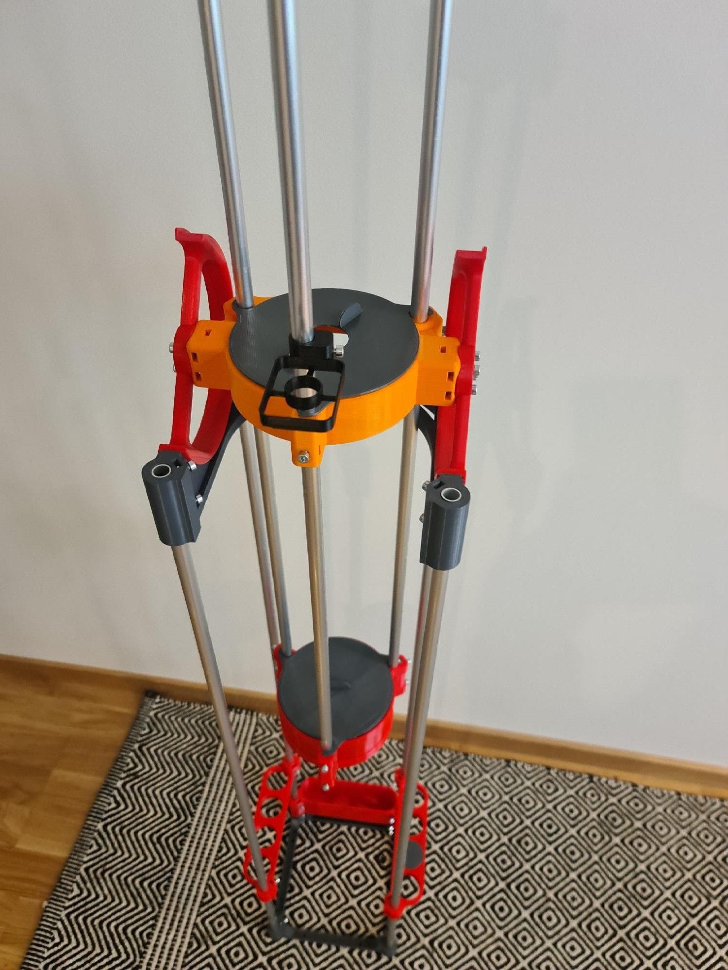
I am building the Hadley telescope and I am doing the metric remix (Printables).
The telescope sits on top of a printed frame that is unstable. I am using 12mm rods (OD) that are hollow. The ID is 10mm. I only measured with caliper on one tube and it was 12.04mm.
I have 2 meter of spare tubing and this week I can print a couple of test versions.
The tube length is 1m for both the base and for the scope. I haven’t printed all parts yet so I don’t know at which height it’ll balance on the mid yet. The 3 tubes on the scope are also 1m in length for a total of 7x 1m rods.
I read the Frame Mount Storage description - and I am sad to say that “Silicon and blue painters tape” do not add up to “sturdy” - someone can do the maths for me, but half a millimetre of movement is going to make two solar systems worth of difference at the other end of the telescope.
I think the tubular frame looks very cool, but at best you’ll wish you built something sturdier, and at worst you might even give up.
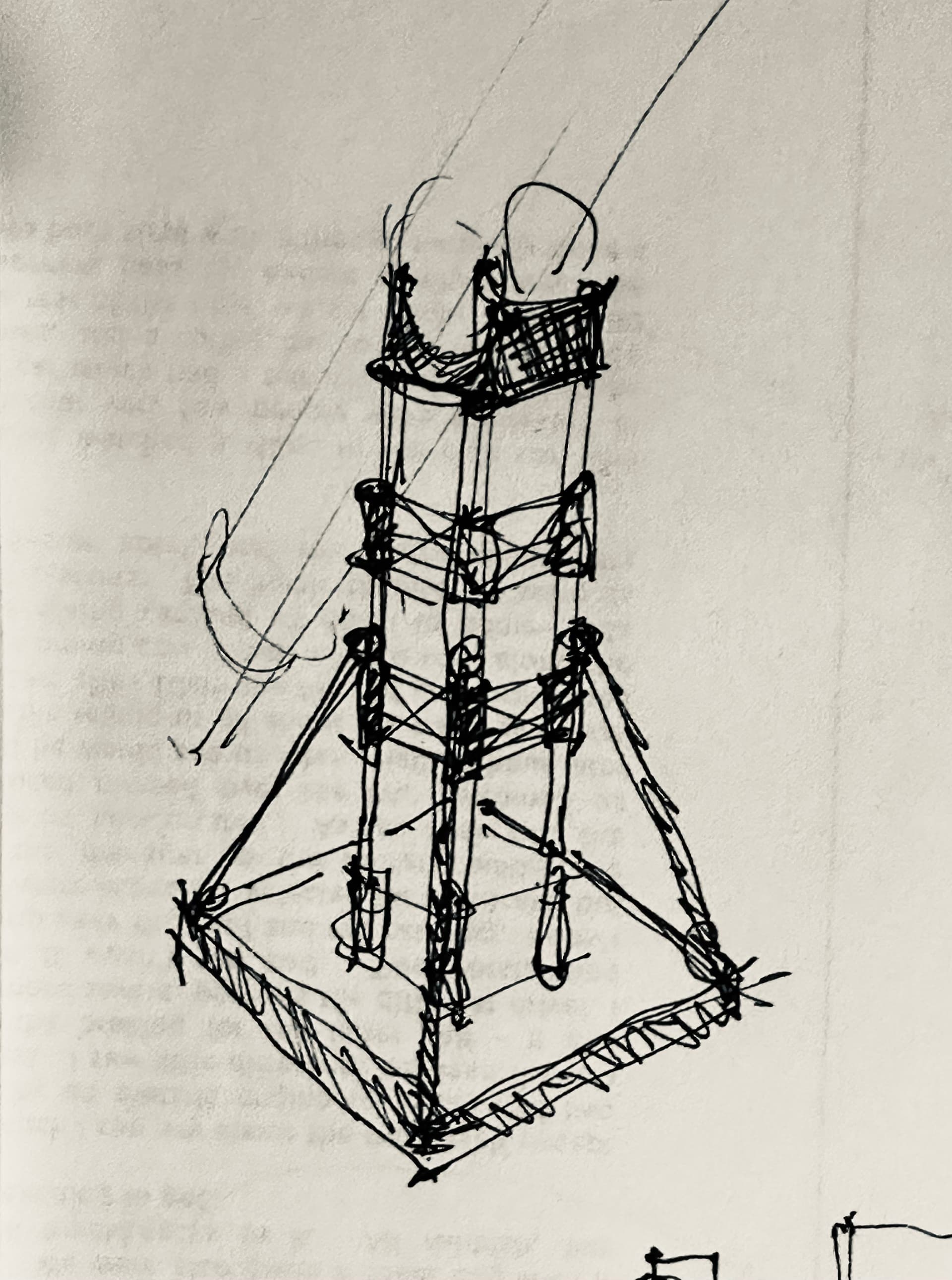
The base looks to be tiny as well at 180mm square, perhaps a circular base would be best, say 450mm (18" diameter?) Pretend my sketch is a circle.
The first thing I’d do would be to make the base as heavy as possible, laminate a few sheets of ply or MDF and I’d ditch the printed base part and simply drill (with a drill press or cnc) holes to insert the legs into.
Next I suggest at least two rows of stiffeners - because you have to have one side open, you will always be chasing your tail so these need to be very much like the top part, as rigid as possible and at least as deep (60mm min).
Finally some external braces would help. I’m sure we could come up with a series of printed connectors to work if you have any interest!
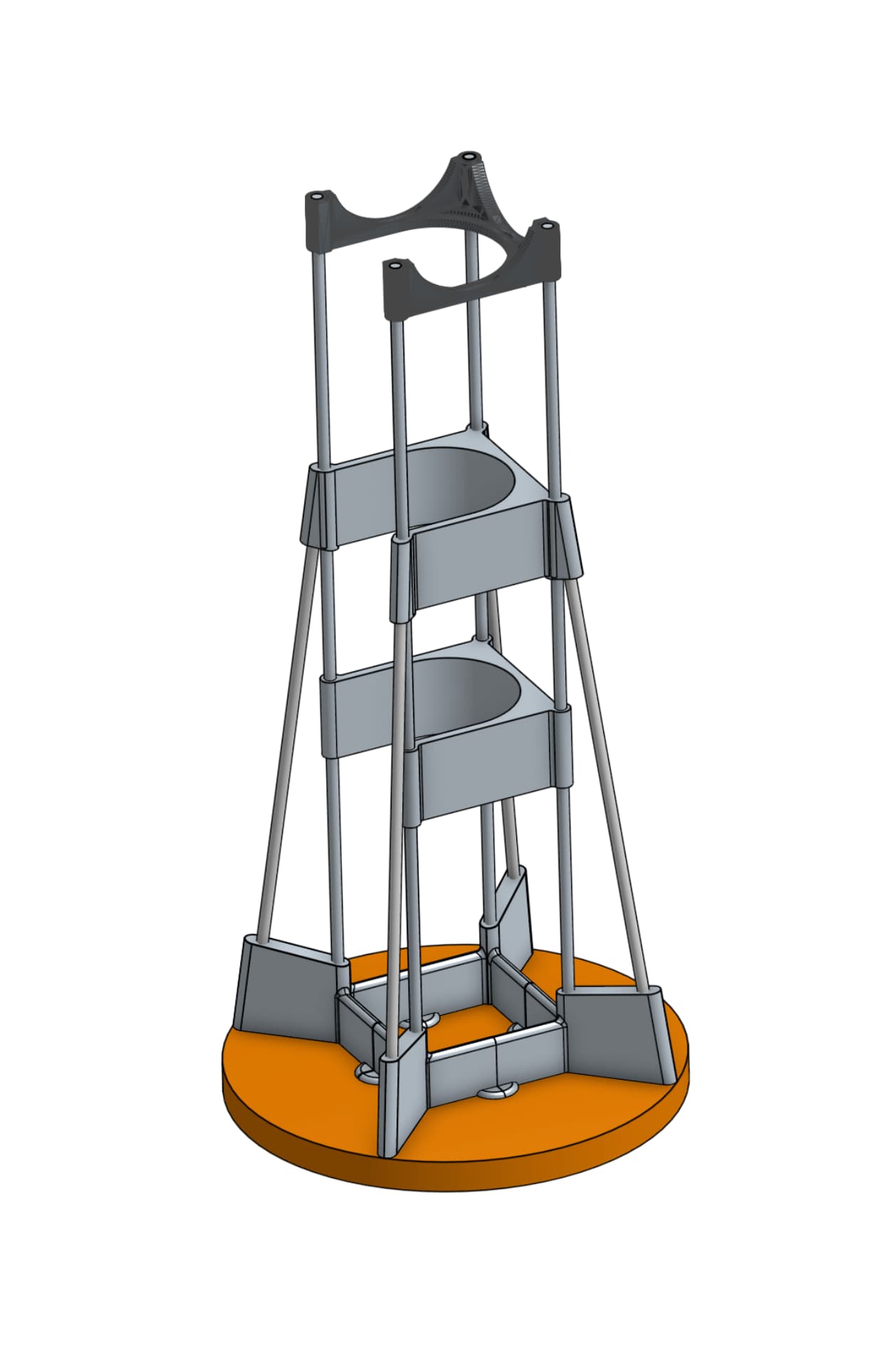
Because I can’t resist a challenge - here’s a quick sketch of how it might work. It needs a lot of detail of course, but I think this is about the minimum you’ll need.
IMHO the bottom is way too short - it doesn’t provide much more stability than a painted circle would!
The top is a bit “weak” as well I think given the size of the structure so I’d change it too. (remember this is just a rough sketch so there’s a lot of tidying up to do.
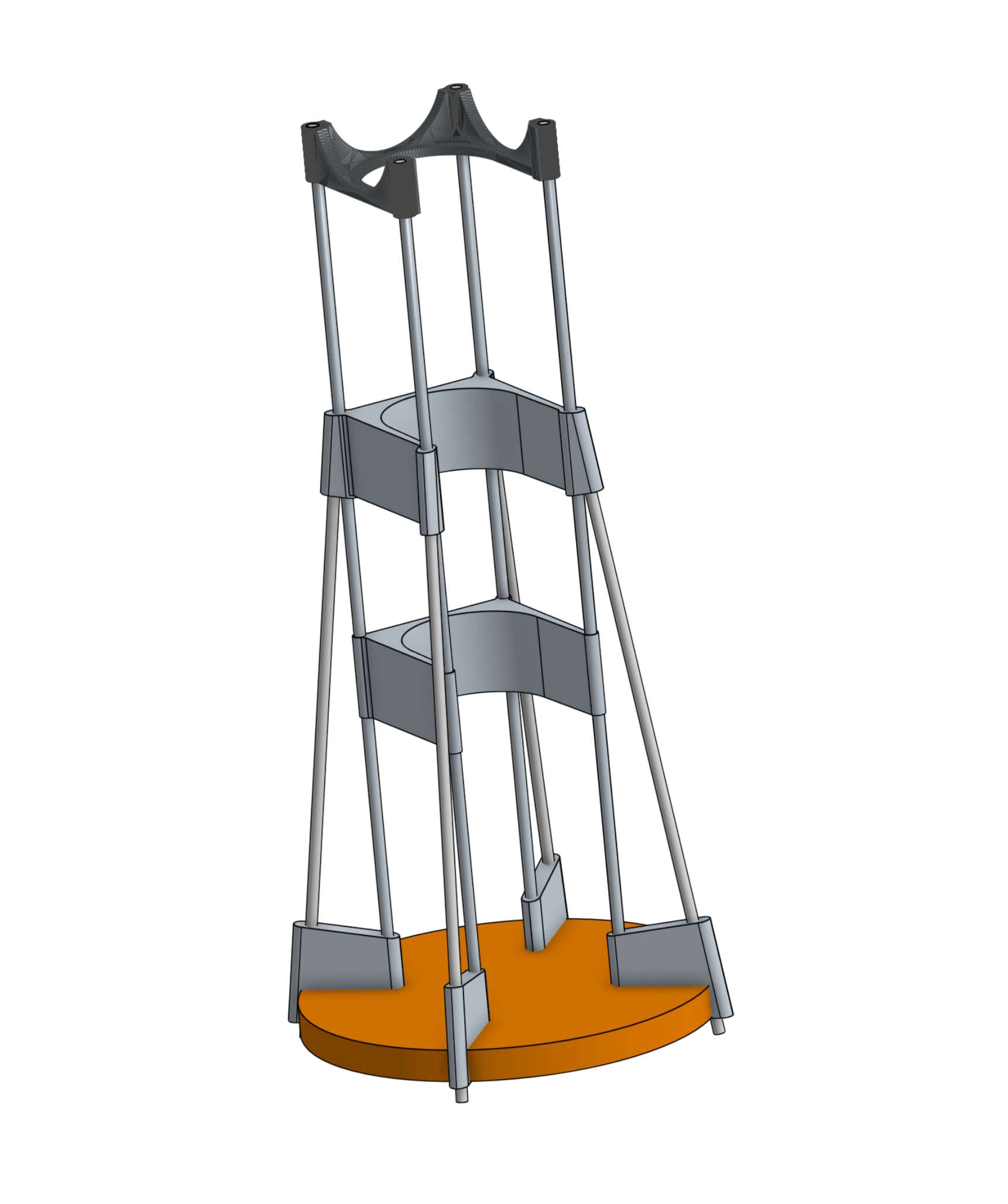
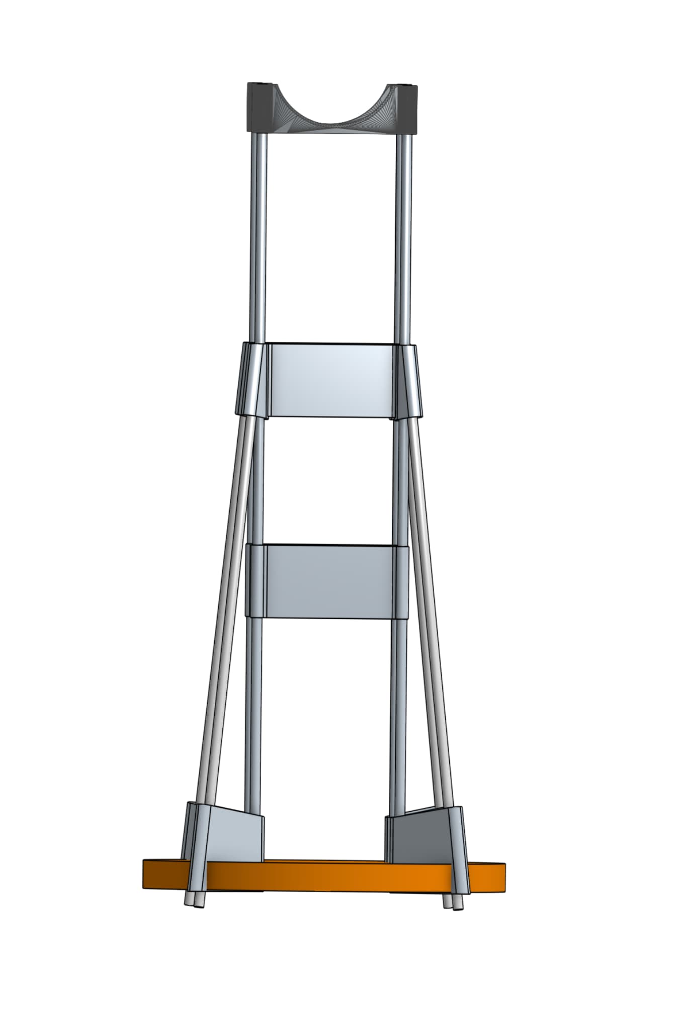
It’s not difficult to incorporate it, but if you don’t want to drill the tubes into the boards (I can understand that) Better to run with something like this:
Of course by the time you’ve done this there’s enough printing to finish an MPCNC and you could cut it in ply. This is an interesting project but it is still a bad idea!
Instead of doing an complete new design, is there no easy way to increase ridigity? Like couplers on the rods with springs in them or something like that? Or a mid brace only?
My gut feel is that the current sketch has poor stiffness in torsion, so your azimuth will be all over the place.
The telescope looks like it is also weak in torsion but it’s ok because there are no torsion loads and twisting will have pretty much no effect. The base is a different story.
I have built a couple poor telescope bases and it was surprising to me how what seems like a small amount of wobble makes the telescope unusable.
I wish I could give tips on a good base but I have only built bad ones
I’ve been hoping you’d pop in. FWIW I totally agree, and was wondering what you’ve done on your bases? I just think the lightweight tube structure is very cool, but fundamentally flawed for its intended purpose.
If you want to use heavy 25mm tube with similar bracing you would be getting somewhere but it’s still unlikely that you’ll be able to keep a one metre tall structure on a 180 mm square base rigid enough. There are very few structures which I would say “heavy is better” - and telescope bases are one of them. As much as I’d love to think otherwise, all the little things add up - every joint gives an opportunity for movement that will affect the use of the scope.
It’s not impossible and if you want your hobby to be building lightweight telescope bases rather than using telescopes, I’m really happy to keep running on this path. I get the joy of invention and none of the despair of failure!
That’s a base I could live with - light and rigid. Not sure about the tiny swivel though - even the slightest amount of play will have massive impact at the other end. I think with cheap table bearings and 18" diameter would be the minimum I’d trust, but this is now me talking through a very hypothetical hat.
The longest lens I use (camera) has something like an 800mm focal length and the difference between a cheap and very expensive tripod is astonishing. I truly wish that wasn’t the case!
The base is about 250 mm square, which is almost exactly twice the area of your 180mm square base.
The height is around 300 mm which is less than a third of the height of yours.
I’m no engineer, but I know that for a given load increasing the lever arm by three times will result in a very big increase in the amount of wobble in your telescope!
The fact that there’s no bracing across the back simply means it can’t work, there is a clue to that if you look at the photos in the TV link and the telescope is mounted on a heavy tripod with legs about 900mm (3ft) apart.
I sound properly curmudgeonly here, and I’d love to see you build it, but don’t be under any illusion that it will be anything but second rate!
All my great ideas remain great, while they are ideas!
You mean the telescope itself wobbles? Fix that first!
What kind of tools do you have for woodworking? I am having a think.
Do you have any plywood scraps lying around? Do you have any other bits of wood, say a couple of 2x4 offcuts? What have you got for the swivel part of the base?
At the moment I have no woodworking tools but next week I’ll travel and then I’ll start to complete my (much overdue) build of the Lowrider. It will be 610mm x 1220mm in working area.
For the svivel part I found this (Printables). What do you think about it?