No tools or materials does limit what we can do here!
The bearing actually looks quite good to me, but I’d make it the biggest diameter you can fit on your printer plate. Note however that the stand is a basic wooden one - one like you should build! The more weight you can get on that bearing the better.
However, since we are already down the tubing rabbit hole (sigh!) this won’t work spectacularly, but I’d be happy to flick you an STL of a simple clamped joint you could print. Or you could download @vicious1 conduit clamps and try scaling them down in your slicer.
Just cut your spare tube into a zillion little bits (around 250mm) and make a diagonal truss frame on each side.
You see I’m up at 4am worrying about you and drawing pipe clamps because I know you won’t let go!
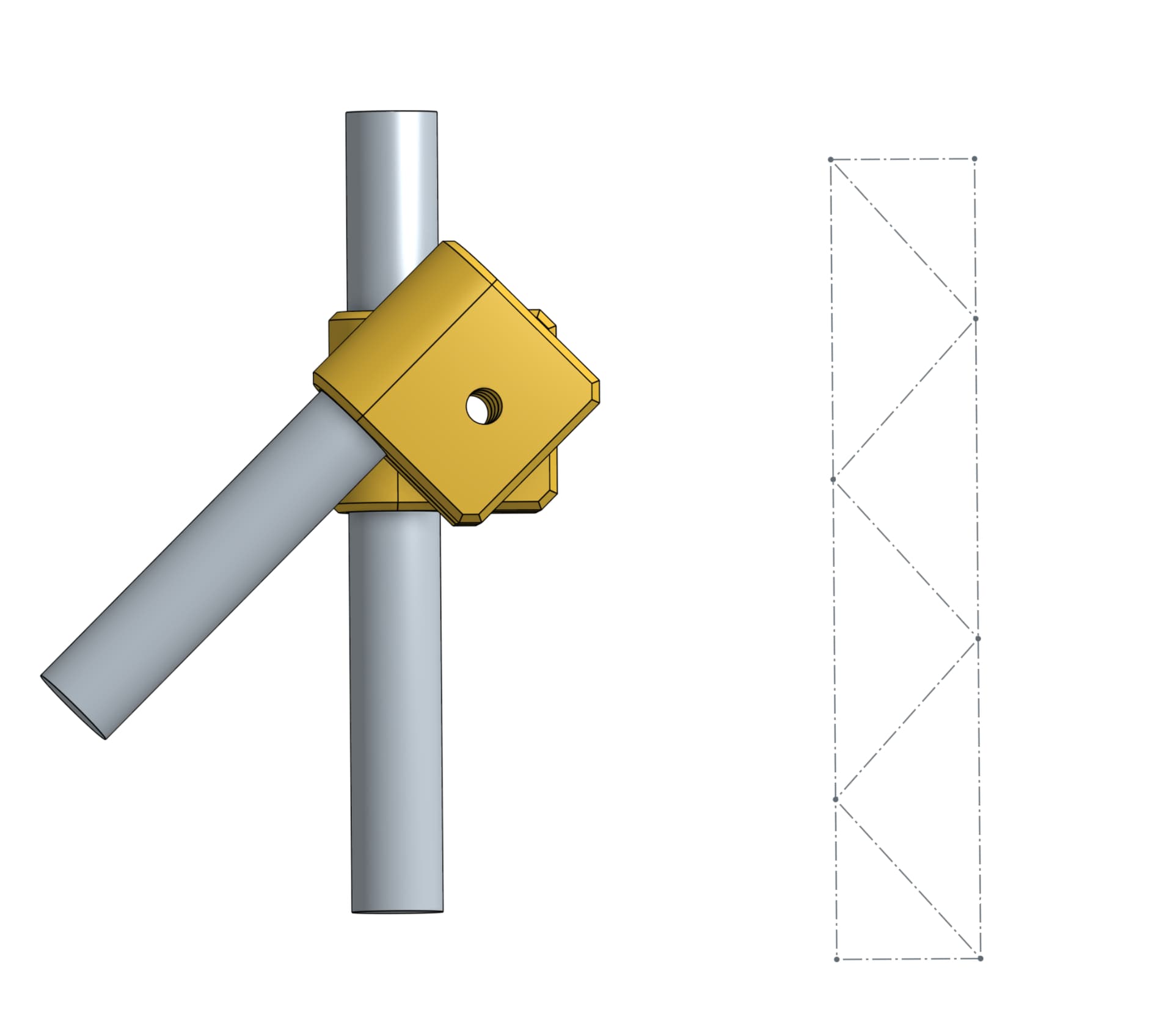
I would normally use machine screws on something like this, with the heads and nuts set flush with the surface. What screws have you got/can get and what size do you want the holes? If you want them nice, send me some details of your screw/nut combo and I’ll adjust - this one has 5mm holes I think.
Print with at least 3 perimeters so there’s no infill on the bit that wraps round the tube.
The bottom plate should probably be a bit wide, and the top part should be thick and strong. In the end it might go full circle back to this this except with six legs that are full height and a beefy bracket on top:
Fun to see my bad ideas getting traction in other people’s projects
a hexapod arrangement is very good for rigidly joining two planes together. it is “exactly constrained” meaning there are 6 supports constraining 6 degrees of freedom so there is no worry about exact alignment between arms, or even exact lengths of the arms if you can otherwise compensate for the two planes being not-exactly parallel to each other in other ways.
I’m not sure you could support that in the middle very well though because you would be putting side loads on the arms and they only ‘work’ when they experience only compression/expansion along their lengths. I guess you could have an intermediate plate and two hexapods going either direction? or do away with the central pivot and just add some mass to the base and pivot it down there.
Good luck with the project! Amateur astronomy seems to have a lot of cool project to build and tinker with.
45? Not 60? I thought it would be equilateral triangles FTW.
At any rate, making the cross members the same length would be best, for manufacturing. And having any triangle is 80% of the strength of the best triangle (Using my gut, made up statistic).
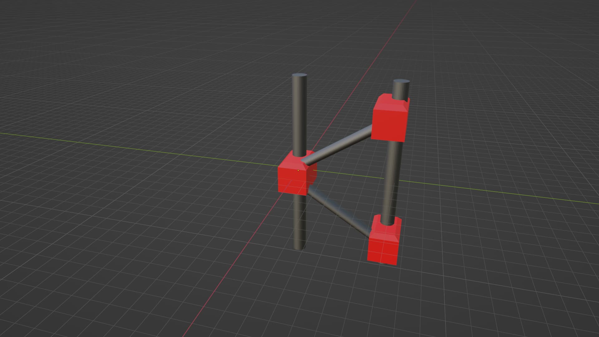
Ok, I read through the thread again and I think you could do this with a six-legged platform to support the top telescope mounting bracket. I mistakenly thought you were trying to stiffen up the telescope itself and not the base.
I’m thinking something like this, but with a top sheet sized/shaped to accept the telescope mount:
I apologise for the non-engineer speak here. I am really having difficulty explaining this without maths and real numbers are a very weak point!
An equilateral triangle is the best shape as it’s self bracing, however we are dealing with a rectangular structure, that needs to be braced from forces coming from opposing directions. If the entire base was a tetrahedron, you would be completely correct (I think!)
If it was a horizontal truss the compression members might well be at 90° and the tension ones at
60° but because it’s a vertical structure the bracing is working in either compression or tension depending on the direction of the load.
I have no idea, but yep!
The problem with that is that the telescope needs to pivot to a full vertical position. Notice that the bases above are “U” shaped or open boxes in plan. That’s one of the killers.
That and the metre height because of the location of the pivot point.
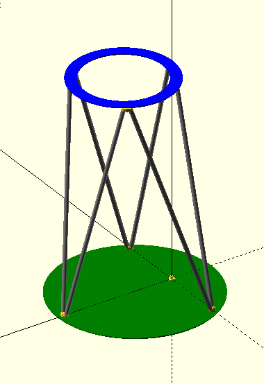
I think six legs could still work. They don’t have to be symmetrical.
At the top, attach two legs each at N, S, and W. At the bottom, one leg goes to NE, two legs go to NW, two legs go to SW, and one leg goes to SE.
Then you have a half-circle at the top that is open on the east side and clearance below it so the telescope can incline without hitting the legs. I think such a setup should be constrained against all six degrees of freedom, but it might depend on the upper plate/block being stiff.
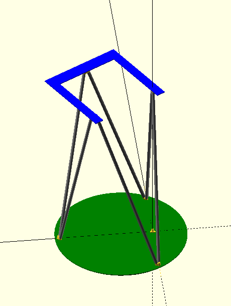
This should work (and still be plenty well constrained).The top plate will have to handle some torsional loads but compared to the original box beam it will be much much stiffer.
Something like this. As long as that upper plate is high enough so the bottom of the telescope clears the legs you should be fine. You could even separate the legs at the bottom for more clearance, but then you will be putting more torsional loads on the bottom plate.