it’s been a while since I have posted something here.
I just wanted to let you know that I have developed a Remix of the Marlin pendant from @TheOrneryMaker .
I faced some problems with the Nano version especially with erratic moves when turning the wheel a bit faster and system hangups when I changed some code portions.
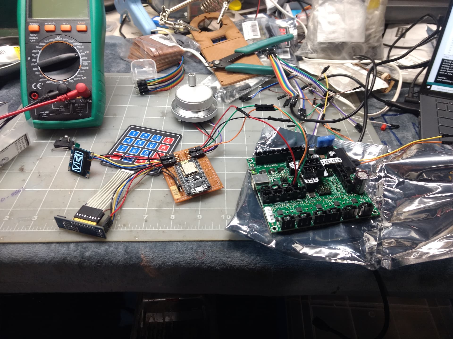
I solved this by porting it to an ESP8266, implementing I2C keypad and thus being able to operate it fully interrupt based. Also implemented some new features like e.g. OTA update.
I have everything documented and open sourced including some video footage on YT.
If you are interested in an affordable fun little hardware project, please check
Big shout out to @TheOrneryMaker for starting the journey! I hope, that thing gets a bit more traction now - I definetly see room for more improvements in the future. And it’s a nice addition to our machines!
Thank you Armin and TheOrneryMaker for putting this together. I am so close to it working but i’m stumped and looking for any suggestions.
keypad works
display works
safety switch works
rotary encoder appears to work when serially monitoring
the problem is when connecting through the black cable from the display (while in Marlin mode), everything powers up and works as expected except the serial commands from the pendant are not getting processed by the machine. The baud rate is set to 250000 in the firmware of the machine as well as your code for the pendant. I triple checked the wiring from the TX of the ESP8266 is to the RX of the black cable from the display. Any suggestion on how to debug or troubleshoot? My understanding is that since I’m using the black cable from the display (in marlin mode) which goes into the SKR 1.2 Pro, I don’t need to activate a 3rd serial port, correct?
The TX and RX pins where the black cable plugs in are active, so no need to activate a 3rd serial port. Are you mapping the cable correctly? TX on the pendent goes to RX on SKR Pro. I cannot tell from the pinout of the SKR Pro if the TFT pins are 5V or 3.3V. If 5V, you may have to do something to receive serial data on the ESP8266.
thanks Robert. I did ensure the TX is going to the RX. However, I will say a point of confusion for me and a little embarrassing…which might be a problem. The SKR Pro 1.2 board has a black connector that connects to the TFT display. I originally unplugged the TFT display and connected the cable from the SKR controller to the pendant and did not get an output. I then figured, maybe it has to go through the display, so I unplugged it from the SKR and connected the pendant straight to the TFT display…which now i do get power. Can you help clarify if the pendant cable should be directly between the controller or the display?
I’m only a hobbyist with electronics, I don’t own an SKR Pro board, and I’ve never programmed an ESP8266. I have done many Arduino projects, and I did design and program my own pendent that I use with my Rambo board. So with that said…
I would not go through the display, at least initially, in connecting your pendant. I would remove the TFT display connection (black cable) and wire the pendant directly to the SKR Pro board.
I assume you are using a module like an ESP8266 12-E. The first thing to figure out is the power. According to the pinout diagram for the SKR Pro, the power on the TFT plug is marked as NPWR. Further reading indicates that NPWR connections are controlled by some jumper on the SKR Pro board. On the 12-E, there are two power connections. One only accepts 3.3V, the other (marked as VIN on pinout diagrams), will accept 5V. If it were me, I’d pick any SKR Pro pin marked explicitly as 5V and avoid any pin marked NPWR. I would connect that power to the VIN on the 12-E. Any ground pin will work. With these two wired up, your board should be powered when the SKR Pro is powered. If that does not work, you have a problem…possibly a burned-out voltage regulator on the 12-E.
As for the serial connection, connect the TX on the 12-E to the RX on the SKR Pro. Don’t connect the 12-E RX pin. I suspect the serial pins on the SKR Pro are 5V pins. Feeding a 5V signal to a 3.3 board like the E-12 can burn out a pin or even damage the board. I took a quick look at the .ino file for this project and found this comment:
// ESP_RX -> CONTROLLBOARD_Serial_TX (optional. ESP is not receiving feedback controllboard)
So, connecting the RX pin is not required. If at some future date you need to receive data from the SKR Pro, and if the pin is really 5V, you can use a simple voltage divider circuit or a voltage shift module. Going the other direction, 3.3V TXT to 5.0V RTX has always worked for me.
If I reverse the A and B connections will everything go in reverse? Right now a counterclockwise rotation goes right, I would prefer it to be a clockwise rotation? Alternatively is there an easy way to do that in software?
It has been a while since I’ve played with a rotary encoder, but reversing A and B should work. If you want to do it in software, you can edit these lines:
Trying to get it working on my bench before putting it all in an enclosure and hooking it to my CNC, running in to an issue where the esp is just looping the 2 boot screens. Did try a reflash but symptom didnt change. Still does it isolated on USB or connected to the Rambo 1.3. Only tweaks to the FW were to redefine the keypad button functions. Not sure where to go from here.
I’ve never programmed ESP board, but from your description, the issue might be either due to some change you made in the firmware, or to a wiring issue, or to a power issue. Unplug everything you can but the screen and try again. If you still have the problem, revert to the original firmware and try again.
One thing that “concerns me” is that it appears you are powering your microprocessor from 5V on the Rambo board, but according to one reference for the ESP board:
external 7-12V power supply connected to the VIN
Edit: Also, are you attempting to read a 5V serial pin from a 3.3V microprocessor?
Have now tried untouched FW, everything but the screen connected, no dice yet.
Saw that noted on the VIN power, after some poking around someone mentioned both the 5v from the usb port and the vin share a common line (protected from back feed) to the boards 3.3v regulator so it should work with 5v and up. Did try a DC source that falls in that 7~12v range with no change.
This is what the serial monitor is spitting out, did have to tell Arduino IDE it was an ESP-12 instead of an ESP-12E (which it was advertised as) for it not to spit out gargage:
Not technically since nothing is being sent to the esp from the rambo, good catch either way, have next to no experience playing with this hardware.
Did a little more digging, looked in to the reset reason and it is apparently a software exception, so clearly I have something wrong in a library or config or w/e (software really isnt a strong suit for me).
I don’t have anything specific to help you with this, but when I have this kind of problem when programming an Arduino board, I pull back to the most minimal configuration I can…some sort of hello world program, or a program to blink an LED. When I get this working, it tells me that 1) my IDE configuration is correct, and 2) the board is alive.
I would go for insufficient power available for the ESP32. Those things require a good current boost during boot as the radio fires up and connects via wifi, boot-loop occurs when the supply voltage dips due to excessive current draw from the supply. It might be better to supply 12v to the ESP32 Vin pin rather than 5v to the ESP32 5vpin and allow the ESP32 on board regulator to supply the current.
My guess is that this is in your code. Maybe something isn’t connecting to wifi and it is just rebooting, rather than trying to limp along without a connection.
I agree. The blink example would be a good choice, to verify your hardware.
But it is an ESP8266.
I have had good luck just powering them over USB and I haven’t had any brown outs (I think because they only operate on 3.3V).