I did order a second ESP8266 just in case, but I will give the LED blink programming a go to see if my current one goes in the round recycling bin or not. Also ordered a bi-di logic converter for the serial voltage difference.
My test power supply has been a lipo when not using usb or trying off the rambo, from what I have dug up they use a regulator to drop the voltage down to 3.3v for the chip, VIN and USB power both go to that vreg.
I have also ran my esps with 5V serials for a long time without converters and it mostly works. The one exception is the neopixel data lines that are very picky about 5V. So I am skeptical that is the issue. I used to wire the 5V Tx to the 3.3V Rx through a resistor (3.3kOhm, or whatever I had nearby) when I was more careful. I haven’t done that in a while though. The resistor should make the 3.3V not have to sink much current when the 5V line is on, but it should still be able to read the uart.
Finally got back around to trying things, both the old board and new board run LED Blink code (also learned about pin definition a little in Arduino, got the on board LED to blink and off D1 ) but neither board will run the pendant code. IDK if I didnt change something that needed to be changed or if the libraries the code is looking for is right. I feel it is user error on this, I am just not sure what I am doing wrong.
Well I can confirm that the code, as downloaded, works on a Wemos D1 R1 - after inserting wifi credentials and any missing libraries. Have you tried grabbing the code again from its source? I can’t remember which, if any, libraries needed downloading but I normally just google any deficient libraries and add the first github offering of the correct name.
Also try erasing the flash completely whilst uploading (tools/erase flash/all flash contents)
apparently the error “ets Jan 8 2013,rst cause:2, boot mode:(3,7)”; comes from the watchdog timer… not that that provides much help
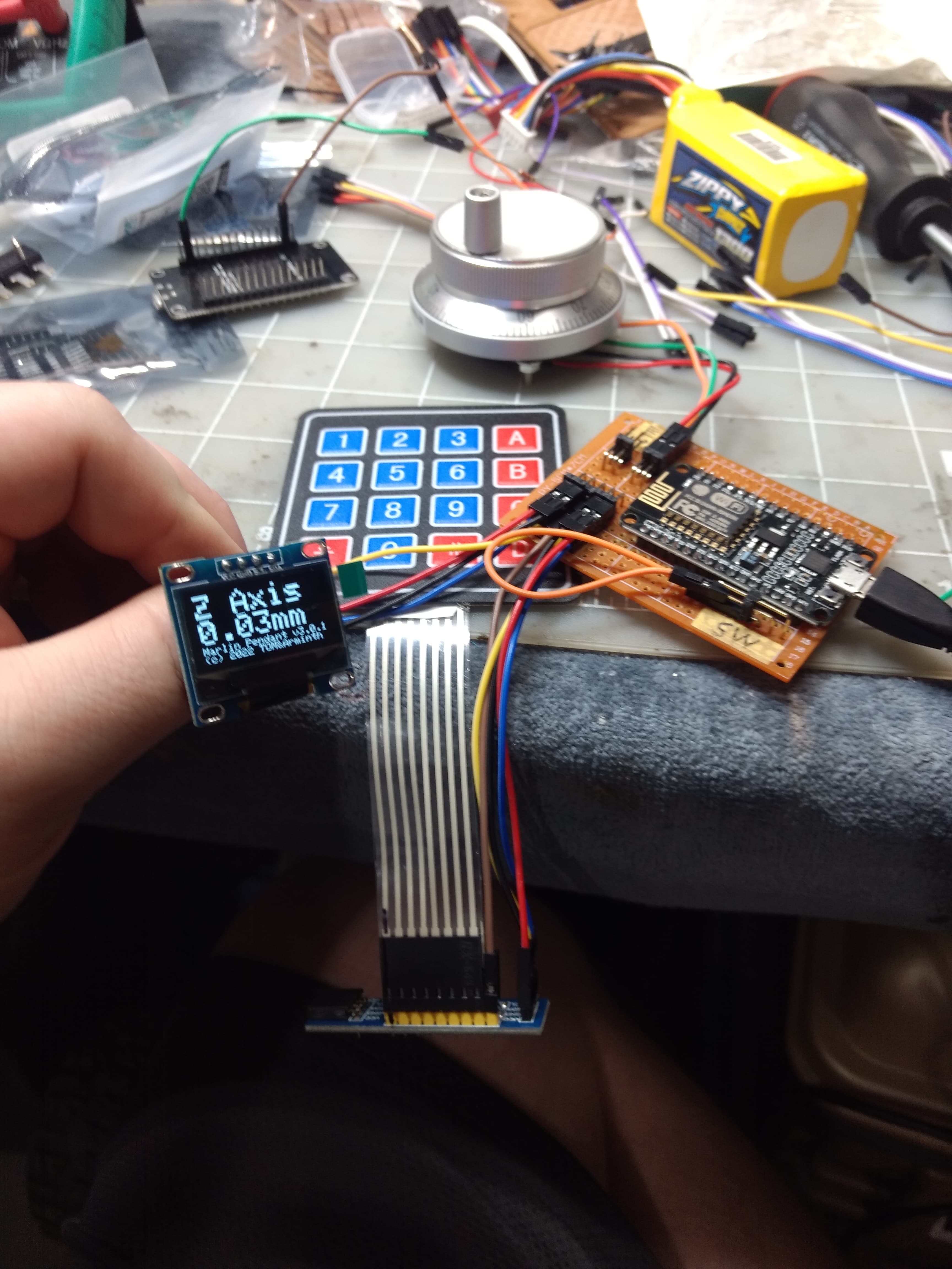
I have zero idea why all of a sudden it worked, maybe it was removing and reinstalling only the libraries the code asked for earlier. Serial plotter is showing all of my buttons are doing their job and the encoder is working. Now to figure out getting it to talk with my Archim.
If you were getting Keyboard not found, it was likely an issue with the interrupt pin on the PCF8574 not having a good connection. I had a similar issue when I built Armin’s version. I missed soldering that connection. Took me a while to sort it out. Glad you got it up and going though. How has it been working out for you?
AFAIK there isn’t one. All the connection details are included in the .ino file. -
// 4x4 keypad
// KEYPAD_rows → PCF8574_p0-p3
// KEYPAD_columns → PCF8574_p4-p7
// PCF8574_IRQ → ESP8266_D3
// PCF8574_SDA → ESP8266_D2
// PCF8574_SCL → ESP8266_D1
// PCF8574_VCC → ESP8266_3.3V
// PCF8574_GND → ESP8266_GND
// PFC8574 I2C adress should be set to 0x21
//
// Safetyswitch (optional with LED)
// GND → Safetyswitch_P1 Safetyswitch_P2 → ESP8266_D7 simple two pin switch
// ESP8266_VIN → R220Ohm-> LED_Anode LED_Kathode->Safetyswith_P2
//
// Rotary Encoder (interchange if rotation is reversed)
// A → ESP8266_D6
// B → ESP8266_D5
// VCC → ESP8266_3.3V
// GND → ESP8266_GND
// ESP8266_GND → Button_P1 Button_P2->D8 (not used yet) simple pin button
//
// SSD1306_OLED 0.96" 128x64
// SDA ESP8266_D2
// SCL ESP_8266_D1
// VCC ESP8266_3.3V
// GND ESP_8266_GND
// SSD1306_OLED I2C adress should be 0x3C
//
// Serial connection and power to Marlin-controllboard
// ESP_VIN → CONTROLLBOARD_5V
// ESP_GND → CONTROLLBOARD_GND
// ESP_TX → CONTROLLBOARD_Serial_RX
// ESP_RX → CONTROLLBOARD_Serial_TX (optional. ESP is not receiving feedback controllboard)
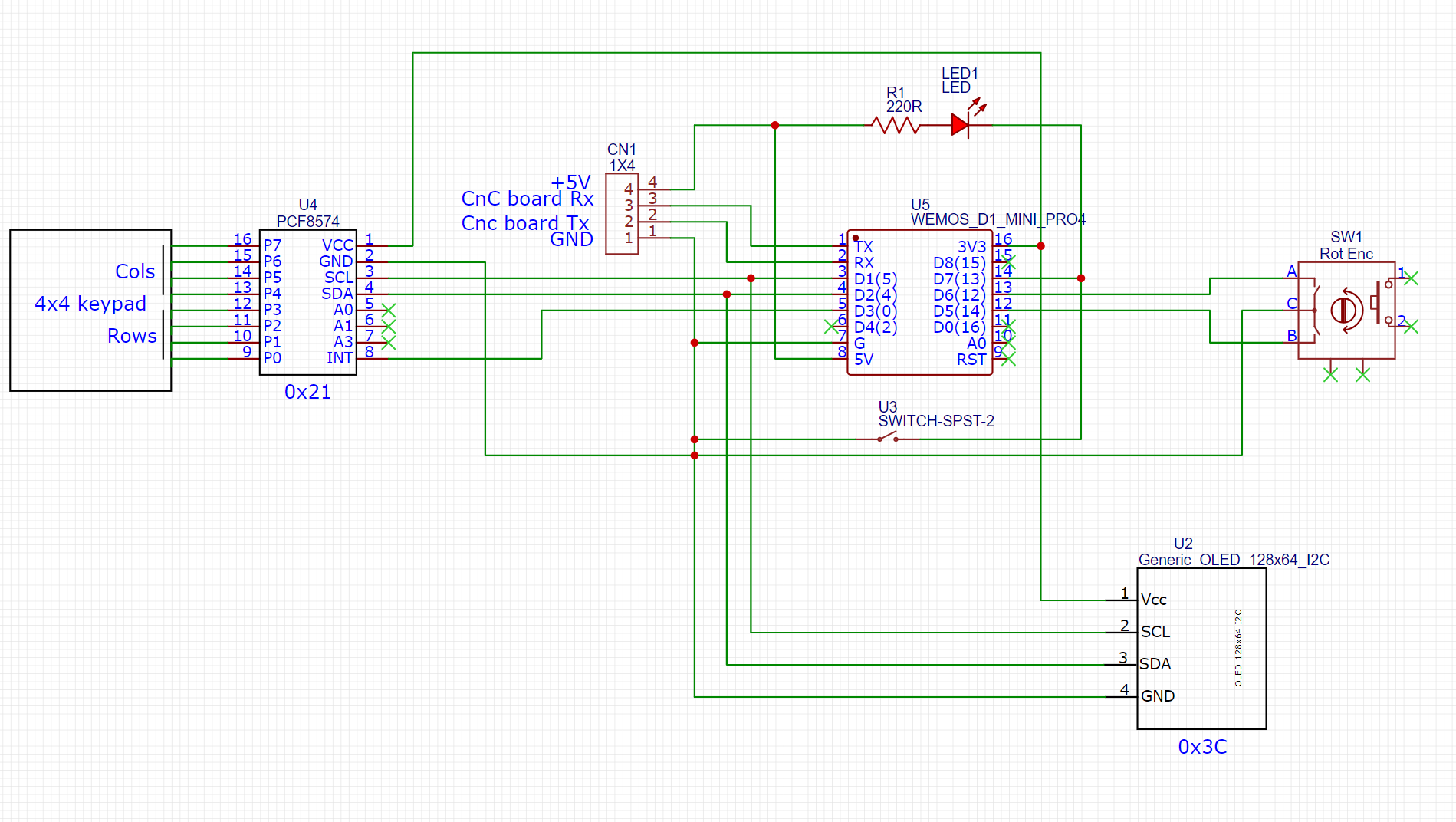
The circuit is quite simple and with a little study you can work out what goes where, there is only the ESP8266, the keypad, the on/off switch & LED, the rotary encoder, the display and the connection lead.
There are two I2C devices, the keypad and the display (the two SDA’s go to ESP D2 pin and the two SCL’s go to D1), the keypad IRQ goes to ESP D3, the encoder’s A and B go to ESP D5 & 6, the switch and LED go to ESP D7 and finally the connection cable goes to the ESP Tx & Rx. Add the power and ground connections.
I really love the idea of pendants, I had a super cheap on on my first CNC, but not the rotary encoder, so, yes this is defiantly on the top 5 next projects.
Thanks, but marlin is currently not supported if i read correctly
(i read wrong, it is supported but not tested)
I think my problem comes from using the same serial (serial 0) as usb port.
I will try switching to serial 2 which is currently used by the LCD (pin 17 RX)
(currently using RAMPS 1.4)
edit: Oke so i did some digging and currently thinking it wont work on Pin 17 RX as this is configured to use the LCD breakout board.
Can someone test for me if their setup works with usb connection open to repetier, octoprint, cnc.js etc. while using the pendant on serial 0?
Edit2: it works!
I added define serial_2 1 in config.h
and use pin 19 (z-max)
For this I changed the pin in pins_ramps:
Z-max -1
I love the idea of this, but I know first hand that I’ll buy the parts, and get 1/3rd through the build, and life will get in the way. It’ll end up sitting in a box like my aquarium light controller, my espd camera, and my laser red dot upgrade.
Long shot question- how much would someone charge to make me one of these, maybe even a wireless version - I have an skr pro 1.2 with an espd module that I use to control using a Samsung tablet.