Yes.
This:
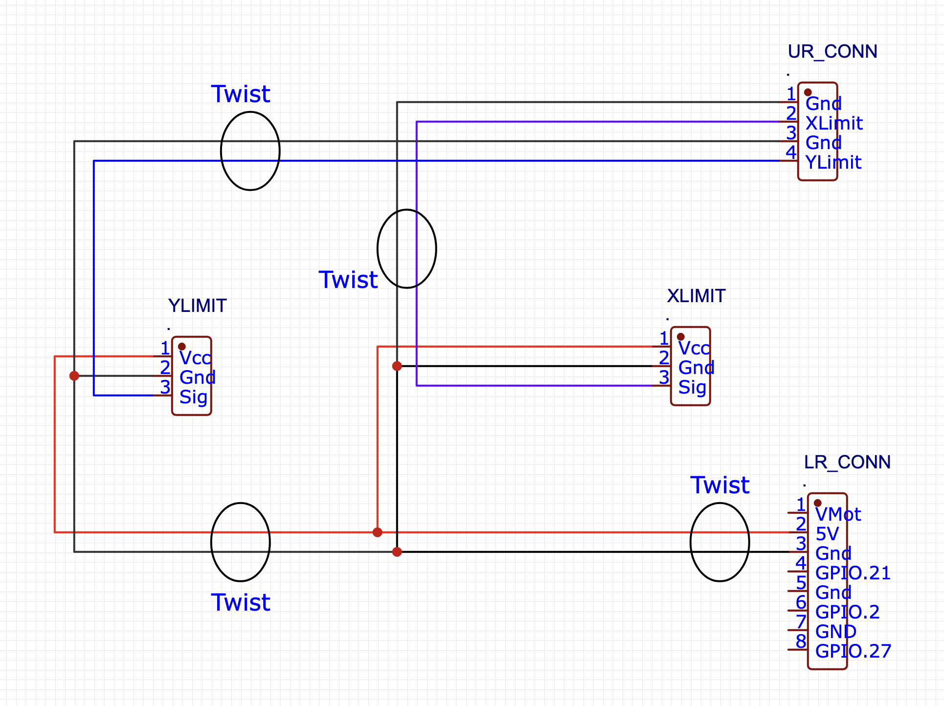
Do twisting of your wire pairs coming and going. Like shown.
Twisting isn’t absolutely essential, but it’s good practice.
If you aren’t able to twist them, at least tape, tie, or bundle them so they’re not random wires in a rats’ nest.
Yes.
This:
Do twisting of your wire pairs coming and going. Like shown.
Twisting isn’t absolutely essential, but it’s good practice.
If you aren’t able to twist them, at least tape, tie, or bundle them so they’re not random wires in a rats’ nest.
quick question; what’s the best way to make the y=splices required in the diagram you provided? I can solder them together at those locations; I’ve done a little bit of that before.
Just asking, but are the 3 points at ground a good idea? That looks like a potential ground loop to me, though it depends on the length of the ground wires going from the UR_CONN to the LR_ CONN connectors. I just run one +5V wire out to both stops.
Great question, and it depends a lot on how the controller has implemented things.
There almost certainly isn’t a ground loop issue here, and probably if anything more of a risk for single ended signals (e.g. just a single wire and not a twisted pair) to pick up some noise.
It likely won’t matter at all for this application.
But without studying the implementation in that particular board, I’d not want to leave off any return connection at any point where one is exposed for a particular use.
OK, all, I got some Y connectors on amazon, wired it as diagramed. I did not make twisted pairs.
Here’s what I find.
When open, each of the end stops is producing a signal on the order of 380 mV. When closed, each of the connectors is making a signal on the order of 4.7 V.
However, I also tested each of the stops when the OTHER STOP was closed. In truth, I got mixed up, and was testing the signal for one when I was actually closing the other one. So, the ‘induced’ signal in one stop when the other stop is in the closed position, if that makes any sense. The induced signal is about 1.6 V. Which, that seems odd to me.
But, in every case, I think I have the stops wired up!
Now what?
We will need to make sure your configuration is correct. Based on your results so far I’m not sure you have the correct pull-up/pull-down config settings. But at least we can do some next testing.
Get into the FluidNC console and pull the diags:
$limits
Do this with none triggered, then trigger one and repeat $limits. Then un-trigger that one and do the other one. Collect $limits again with the other one triggered.
That will let us know what FluidNC thinks is happening with your endstop circuits.
How are your pins configured in the config.yaml that you are running?
With both open:
$limits
Send ! to exit
Homing Axes : xy
Limit Axes :
PosLimitPins NegLimitPins Probe
: xy
: xy
: xy
: xy
: xy
: xy
: xy
: xy
: xy
: xy
: xy
: xy
: xy
: xy
: xy
: xy
: xy
: xy
: xy
: xy
: xy
: xy
: xy
: xy
: xy
: xy
: xy
: xy
: xy
: xy
: xy
: xy
!
ok
With one closed:
$limits
Send ! to exit
Homing Axes : xy
Limit Axes :
PosLimitPins NegLimitPins Probe
:
:
:
:
:
:
:
:
:
:
:
:
:
:
:
:
!
ok
With the other closed:
$limits
Send ! to exit
Homing Axes : xy
Limit Axes :
PosLimitPins NegLimitPins Probe
:
:
:
:
:
:
:
:
:
:
:
:
:
!
ok
I am not sure; help me understand how to answer this question
zip up your config.yaml file and post it here.
We can take a look at it from there.
You can also cut/paste it into a message by having a line of 3 back single quotes (`) both before and after the text of the YAML file, but that won’t necessaroly show us syntax errors like extra spaces at the end of a line.
config.zip (832 Bytes)
name: “Table ZenXY”
board: “FluidNC Pen/Laser 2209”stepping:
engine: RMT
idle_ms: 255
dir_delay_us: 1
pulse_us: 2
disable_delay_us: 0uart1:
txd_pin: gpio.17
rxd_pin: gpio.16
rts_pin: NO_PIN
cts_pin: NO_PIN
baud: 115200
mode: 8N1kinematics:
corexy:start:
must_home: falseaxes:
shared_stepper_disable_pin: gpio.13:highx:
steps_per_mm: 100
max_rate_mm_per_min: 8000
acceleration_mm_per_sec2: 300
max_travel_mm: 405
soft_limits: false
homing:
cycle: 2
positive_direction: false
mpos_mm: 25.00
feed_mm_per_min: 500.000
seek_mm_per_min: 1000.000
settle_ms: 500
seek_scaler: 1.100
feed_scaler: 1.100motor0: limit_neg_pin: gpio.36:low #Diag pin is gpio.34 tmc_2209: uart_num: 1 addr: 0 r_sense_ohms: 0.110 run_amps: 0.333 hold_amps: 0.333 microsteps: 16 stallguard: 0 stallguard_debug: false toff_disable: 0 toff_stealthchop: 5 toff_coolstep: 3 run_mode: CoolStep homing_mode: CoolStep use_enable: false direction_pin: gpio.12 step_pin: gpio.14 disable_pin: NO_PINy:
steps_per_mm: 100
max_rate_mm_per_min: 8000
acceleration_mm_per_sec2: 300
max_travel_mm: 335
soft_limits: false
homing:
allow_single_axis: true
cycle: 1
positive_direction: false
mpos_mm: 5.0
feed_mm_per_min: 500.000
seek_mm_per_min: 1000.000
settle_ms: 500
seek_scaler: 1.100
feed_scaler: 1.100motor0: limit_neg_pin: gpio.39:low #diag pin is gpio.35 tmc_2209: uart_num: 1 addr: 1 r_sense_ohms: 0.110 run_amps: 0.333 hold_amps: 0.333 microsteps: 16 stallguard: 0 stallguard_debug: false toff_disable: 0 toff_stealthchop: 5 toff_coolstep: 3 run_mode: StealthChop homing_mode: StealthChop use_enable: false direction_pin: gpio.26 step_pin: gpio.25 disable_pin: NO_PINspi:
miso_pin: gpio.19
mosi_pin: gpio.23
sck_pin: gpio.18sdcard:
cs_pin: gpio.5
card_detect_pin: NO_PINcoolant:
flood_pin: NO_PIN
mist_pin: NO_PINprobe:
pin: NO_PIN
I’ve been re-reading this topic, and am de-zombifying it.
It looks like @LosTyger is still having difficulty with the endstops, so I’d like to get back into troubleshooting this.
First step, measure the voltage at the Jackpot board with a DMM or oscilloscope while trying to home. We need to see what the control signal voltage is doing while this is happening.
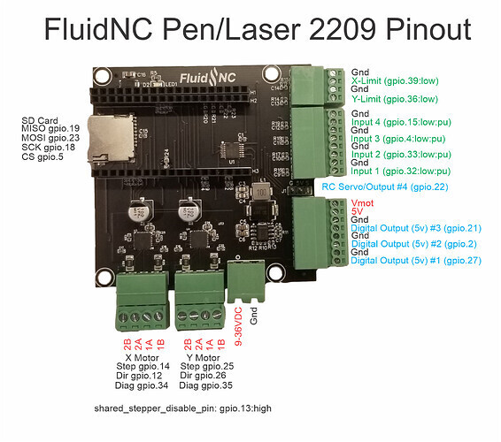
From your config, it looks like:
x:
...
 motor0:
   limit_neg_pin: gpio.36:low
So, for this the connector in the upper right between GND and Y-Limit (Note- are you seeing the discontinuity here? The hardware defines this as Y-limit, but your config is defining this as X limit. This could be the whole problem).
Then, for your Y: the config shows:
y:
...

motor0:
  limit_neg_pin: gpio.39:low
In a similar way, the board picture above shows this as the upper right connector, top pin, but again the picture defines this as X-Limit and your config defines it as Y-limit.
Either way, these are the way I’d test it. If you have a scope, put a scope on these two points. If you have 2 DMMs, put the two DMMs on these points. If you only have one DMM, monitor one point as you try to home an axis, and then switch and monitor the other point as you try to home that same axis.
Then watch those two points as you switch to homing the other axis.
We want to build a truth table of what voltages you see, on which pin, as you try to home X and as you try to home Y.
Edit to add: How did you wire this? Which sensor goes to which spot?
OK, here’s what happens when I hit the home switch in the Fluid NC interface:
$G
$H
[MSG:INFO: ALARM: Homing Fail Pulloff]
ALARM:8 Homing fail. Pull off travel failed to clear limit switch. Try increasing pull-off setting or check wiring.
ok
<Alarm|MPos:0.000,1.000,0.000|FS:0,0|Pn:XY|WCO:0.000,0.000,0.000>
I tested the pins vs a ground pin and saw about 370 mV, all the time, did not change when I hit the home button. The alarm copied above hits very quickly on the interface.
I even swapped the connection of the signal wires for the endstops between the pins and didn’t see any change.
Was there any motion at all?
Edit: We might want a variant of this exercise to charactarize your signals/sensor wiring.
Power down the machine and very slowly move the position so that both X and Y are at the home position (where the sensor should be triggered.). Power up and repeat the voltage measurement for both axis. Then, power down.
Again VERY SLOWLY, move the position so both axis are somehwere in middle of travel (where neither sensor should be triggered). power up, repeat the voltage measurement.
I suspect there are two things at play here, but want to see the data.
OK, in home position, the voltages from pin to ground are:
pin 36: 4.85 V
pin 39: 1.54 V
I then was looking hard at the home position and thought that one of the axis (which, I think of as the y axis) maybe wasn’t getting into the path of the optical end stop beam, so I blocked it with something else and I think maybe I was right.
With the y axis beam physically blocked,
pin 39: 4.83V
In the NOT-home position, the voltages from pin to ground are:
pin 36: 374.8 mV
pin 39: 359.2 mV
Hoping this helps? Also, upon hitting the home button on the web interface, there was no motion, just error code.
OK, so that was one issue- one sensor wasn’t getting triggered.
So, now that sensor is being triggered. That leads us to the next issue:
Your sensors are outputting .380V in one state, 4.85V in the other. The ESP-32 wants 0-3.3V.
I’ll double check the pen/laser board design when I get a chance, but you may need level converters or at least a resistor divider network to make the IO work.
While I’m off doing this, if you’ve fixed the sensor triggering we can repeat the measurements with an additional detail:
Power off the board. Slowly move both axis to home.
Power up. Measure the voltage, and also send a ? command in the terminal. Report what FluidNC sees.
Power off the board. slowly move both axis to somewhere in the middle of motion.
Power up. Repeat the voltage measurement, and again send a ? command in the terminal. Report what it says.
Stand by for details about the pullup voltage stuff after I check.
OK, home position:
Pin 36: 4.86 V
Pin 39: 1.55 V
Suspecting that the end stop on the 3D printed piece that I have on the table right now is not long enough to fully engage the beam. I’m not very worried about that; I have a 3D printer and can modify that when I put together my final version of the build.
Fluid NC response to ? prompt
Blockquote
$G
?
<Idle|MPos:0.000,0.000,0.000|FS:0,0|WCO:0.000,0.000,0.000>
Not-home position:
Pin 36: 383 mV
Pin 39: 357.5 mV
Fluid NC response to ? prompt
Blockquote
$G
?
<Idle|MPos:0.000,0.000,0.000|FS:0,0|Pn:XY|Ov:100,100,100>
<Idle|MPos:0.000,0.000,0.000|FS:0,0|WCO:0.000,0.000,0.000>
OK so this is FluidNC telling us that when in the Homed position, it doesn’t see either limit switch active.
And:
<Idle|MPos:0.000,0.000,0.000|FS:0,0|Pn:XY|Ov:100,100,100>
Here, you’re in the not-homed position, but FluidNC is reporting X and Y are triggered (active).
That’s what the Pn:XY means. Specifically, it sees X and Y as triggered.
So, this means you have your limit pin definitions inverted in your config file.
For your X config, change the line above to read as follows (Remove the :low )
motor0:
  limit_neg_pin: gpio.36
Similarly, in your Y change this:
motor0:
  limit_neg_pin: gpio.39:low
To be this (Again remove the :low ) :
motor0:
  limit_neg_pin: gpio.39
Repeat these tests (including sending the ? command)
If the Pn:YX flips and is correct, then try an actual homing sequence.