I’m studying your $SS outputs.
There’s something syntactically wrong with those, and it must be due to the different stepping engine.
I’ll keep looking at this. We’re close- but there’s a nuance about your board that I don’t understand yet.
They all say this. That seems weird.
It looks like uart needs to be at the top level and uart_num needs to be in each tmc section:
http://wiki.fluidnc.com/en/config/uart_sections
I would expect uart1: at the top (meaning left side, no spaces, not necessarily above everything else). And then uart_num: 1 under each tmc section.
It looks like stuff changed a bit and these examples are too old.
I would edit and upload, but I’m on mobile for a while.
Yep. This is what I changed before to make that error go away. It’s weird that the sample files aren’t valid.
What’s weird is I thought this was already the case in the various config files.
Unless there’s some copy/paste involved here I don’t know how that could be the case.
I don’t know how else to proceed or what to change, since I don’t have one of those boards to test with.
The stepper engine is different as these boards don’t use the shift register mechanism that the Jackpot or 6 Pack use.
Jason’s file is definitely the most correct.
How was the board powered when you ran this test?
Is it possible you only had USB power at the start? You need to have 12V on to power the TMC drivers. It will only send the config bytes when the ESP boots. So you need to connect 12V before connecting USB to power.
Yep, sorry about that guys, I had it plugged into my computer to transfer files and then I just left it plugged in there to test it. I’ll go get the test done properly.
1 Like
Jason’s file, powered by a cell phone wall wart (highest power thing I have at hand at the moment):
$SS
[MSG:INFO: FluidNC v3.7.17 GitHub - bdring/FluidNC: The next generation of motion control firmware]]
[MSG:INFO: Compiled with ESP32 SDK:v4.4.4]]
[MSG:INFO: Local filesystem type is littlefs]]
[MSG:INFO: Configuration file:config.yaml]]
[MSG:INFO: Machine Table ZenXY]]
[MSG:INFO: Board FluidNC Pen/Laser 2209]]
[MSG:INFO: UART1 Tx:gpio.17 Rx:gpio.16 RTS:NO_PIN Baud:115200]]
[MSG:INFO: SPI SCK:gpio.18 MOSI:gpio.23 MISO:gpio.19]]
[MSG:INFO: SD Card cs_pin:gpio.5 detect:NO_PIN freq:8000000]]
[MSG:INFO: Stepping:RMT Pulse:2us Dsbl Delay:0us Dir Delay:1us Idle Delay:255ms]]
[MSG:INFO: Axis count 3]]
[MSG:INFO: Shared stepper disable gpio.13]]
[MSG:INFO: Axis X (25.000,430.000)]]
[MSG:INFO: Motor0]]
[MSG:INFO: tmc_2209 UART1 Addr:0 CS:NO_PIN Step:gpio.14 Dir:gpio.12 Disable:NO_PIN R:0.110]]
[MSG:INFO: X Neg Limit gpio.36:low]]
[MSG:INFO: Axis Y (5.000,340.000)]]
[MSG:INFO: Motor0]]
[MSG:INFO: tmc_2209 UART1 Addr:1 CS:NO_PIN Step:gpio.25 Dir:gpio.26 Disable:NO_PIN R:0.110]]
[MSG:INFO: Y Neg Limit gpio.39:low]]
[MSG:INFO: Axis Z (-1000.000,0.000)]]
[MSG:INFO: Motor0]]
[MSG:ERR: X Axis TMC driver not detected - expected 0x21 got 0x0]]
[MSG:ERR: Y Axis TMC driver not detected - expected 0x21 got 0x0]]
[MSG:INFO: Kinematic system: CoreXY]]
[MSG:INFO: Using spindle NoSpindle]]
[MSG:INFO: STA SSID is not set]]
[MSG:INFO: AP SSID FluidNC IP 192.168.0.1 mask 255.255.255.0 channel 1]]
[MSG:INFO: AP started]]
[MSG:INFO: WiFi on]]
[MSG:INFO: Captive Portal Started]]
[MSG:INFO: HTTP started on port 80]]
[MSG:INFO: Telnet started on port 23]]
ok
I might also need to state, just so that no one makes a wrong assumption, that there is every possibility that I have not gotten my steppers wired to the board correctly. If the messages above could be generated by that error…well, like I said, I’m an idiot, and there’s no reason to think I got that right.
What are the ratings on that wall wart?
Try this again when you can find something that sources at least 12V, 3A.
A picture of it all wired up would help too.
OK, gang, I’m still working on this, still appreciate all the help, and might still be an idiot. Here’s my current problem.
I got a power supply, to ensure that the board was getting enough juice to do the things.
The power supply has the ability to go up to 12V and 3 amps, and has the USB micro connector, so I thought it would be good enough. I didn’t find a lot of options on this, so if ya’ll have a better recommendation, I’m all ears.
I plugged the power supply into the board. When I do that, I can see the ‘Network’ that the board is broadcasting (FluidNC), but I can’t connect to it. As in, the computer tells me I can’t connect to that network. When I plug the board in via USB directly to my computer, I can connect to the board, log into the Fluid NC web interface, swap files around, etc.
So, at the moment, I find that I can’t log into the board to run the diagnostic $SS command to see what might happen with the board when connected to the power supply.
No idea what’s going on. Any thoughts?
Can you post a picture of that power supply and ideally of the data label? 12V 3A with a micro USB connector doesn’t make any sense.
5V 3A and micro USB would be something that you’d use to power a rasberry pi, but not a Jackpot or an ESP-32. (You could probably power the ESP32 ONLY with it, but if you’re trying to load/test the ESP-32 separately you’re better off with a USB data cable connected to your host computer.)
To power your controller, you want a 12V or 24V power supply, and we’ll trim off the connector to install the leads into the screw terminals on your controller.
When you post a better picture that we can advise better next steps.
The power supply you’ve bought has a max output power of 36 Watts.
the ones Ryan sells in the shop are 60 Watts and the ones he links to on Amazon are 72 Watts
So yes I would say the one you have there is not supplying enough power if you have it at max output and are having problems.
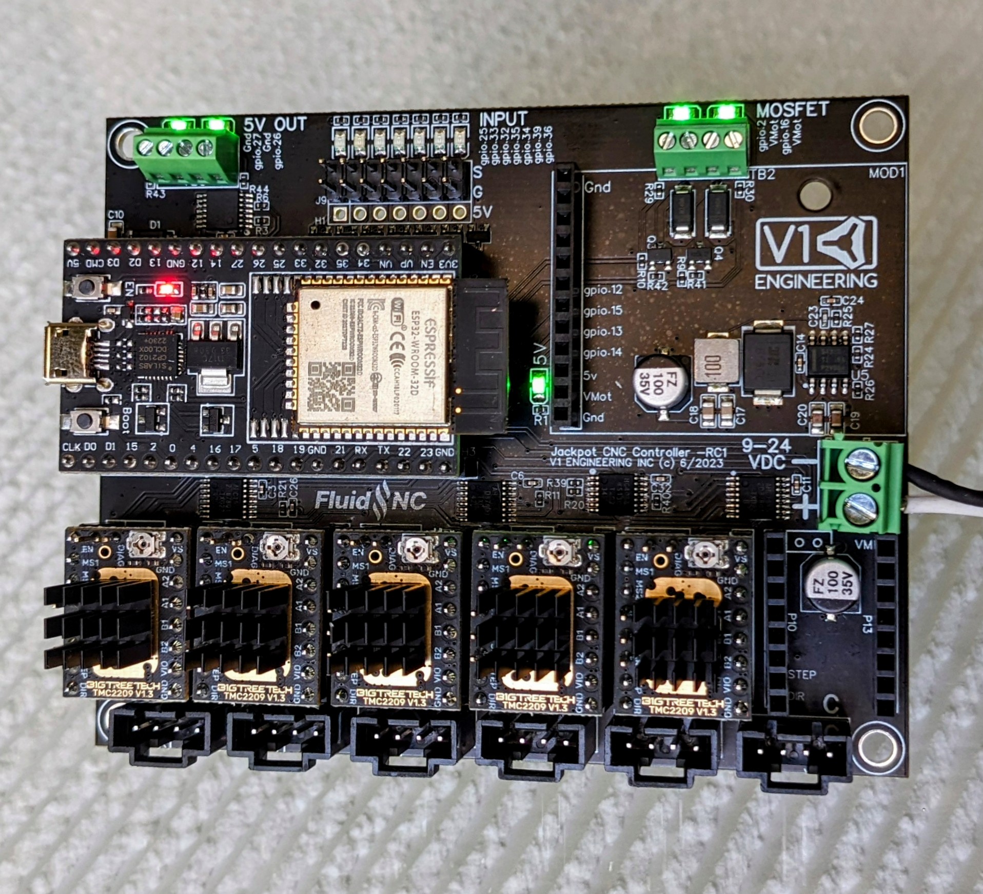
When you say you’re plugging it into ‘the board’ can I just check you’re putting power to the green 2 terminal connector to the right edge of the jackpot board marked 9-24VDC in this picture
Sorry for the delay, I’ve been out conferencing and been coast to coast over the last couple of weeks.
I think we have made significant progress. I used a proper power supply, connected to the proper terminals, and got the below output:
$G
$S
$Grbl/HomingCycleEnable=1
$Grbl/HardLimitsEnable=0
$Grbl/SoftLimitsEnable=0
$Grbl/Resolution/Z=80.000
$Grbl/Resolution/Y=100.000
$Grbl/Resolution/X=100.000
$Grbl/MaxRate/Z=1000.000
$Grbl/MaxRate/Y=8000.000
$Grbl/MaxRate/X=8000.000
$Grbl/Acceleration/Z=25.000
$Grbl/Acceleration/Y=300.000
$Grbl/Acceleration/X=300.000
$Grbl/MaxTravel/Z=1000.000
$Grbl/MaxTravel/Y=335.000
$Grbl/MaxTravel/X=405.000
$Start/Message=Grbl \V [FluidNC \B (\R) \H]
$Firmware/Build=
$SD/FallbackCS=-1
$Report/Status=1
$Config/Filename=config.yaml
$Message/Level=Info
$WiFi/Mode=STA>AP
$Sta/SSID=
$Sta/Password=********
$Sta/MinSecurity=WPA2-PSK
$WiFi/FastScan=OFF
$Sta/IPMode=DHCP
$Sta/IP=0.0.0.0
$Sta/Gateway=0.0.0.0
$Sta/Netmask=0.0.0.0
$Sta/SSDP/Enable=ON
$AP/Country=01
$AP/SSID=FluidNC
$AP/Password=********
$AP/IP=192.168.0.1
$AP/Channel=1
$Hostname=fluidnc
$HTTP/BlockDuringMotion=ON
$HTTP/Enable=ON
$HTTP/Port=80
$Telnet/Enable=ON
$Telnet/Port=23
$Notification/Type=NONE
$Notification/T1=
$Notification/T2=
$Notification/TS=
ok
<Idle|MPos:0.000,0.000,0.000|FS:0,0|WCO:0.000,0.000,0.000>
$J=G91 G21 F1000 Y10
ok
<Jog|MPos:0.000,0.090,0.000|FS:1414,0|Ov:100,100,100>
$J=G91 G21 F1000 Y10
ok
<Jog|MPos:0.000,10.130,0.000|FS:1414,0>
$J=G91 G21 F1000 Y10
ok
<Jog|MPos:0.000,20.070,0.000|FS:1414,0>
$J=G91 G21 F1000 X10
ok
<Jog|MPos:1.430,30.000,0.000|FS:1414,0>
$J=G91 G21 F1000 X10
ok
<Jog|MPos:12.620,30.000,0.000|FS:1414,0>
I also (as you can probably tell from the output copied above) used the jog function in FluidNC to get some movement from the table, and it did move! So, significant progress.
So, I think I am now really close.
I have two issues which I think are remaining:
-
How to wire in my end stops. I think there was some discussion, but I’m not sure there was a consensus, and so I know that needs to be done.
-
How to program in patterns. I have done this before, but would really appreciate a point in how it should best work with the new control board.
BIG THANKS for bringing me this far!
All,
I was hoping to put this back on the radar of the collective.
How should I wire up my end stops? I think there was some discussion, but I don’t think there was a consenseus?
I’m pretty sure I can make patterns via Sandify and upload those via an SD card; is there a standard set of gcode lines that people use at the beginning and end of their patterns?
Depends. The optical end stops called for on the ZenXYv2 need a 3 wire connection. Many of the FluidNC boards including Jackpot have a 2 pin plug, so you need to draw +5V from somewhere else.
If you are using microseitches, the common way is to use normally closed switches, which open when triggered.
I add a homing sequence before, so I know the ball’s position. In Fluid, it’s $H and in Marlin it’s G28 your homing sequence on the ZenXY needs to home Y before X
I confess I"ve skimmed, but not thouroughly re-read, this thread.
Have you purchased / installed any end stops so far?
If so, what model of endstops and what mounts did you use?
Thanks for continuing to help.
I believe I went with the opticals called for on the ZenXYv2, which have a 3 wire connection. I also used the mounts from the ZenXYv2, so they seem to be mounted well and in place, and there definitely are three connectors for each of the two end stops.
These are the ones that I ordered:
Optical end stops
Before I go any further, let me say out loud that if the easiest thing to do were to get different end stops, I could TOTALLY DO THAT. So, if the solution to the current situation were to go out and get different end stops, please feel free to recommend that.
The FluidNC board that I have, to be honest, is a mystery to me. I’m an engineer, but not this flavor of engineer. I think I found some information, but am still looking to confirm and for advice.

I can say pretty sure that they have to connect down the left side of this image, because the power input and steppers are connected to all available connections on the top of that image, and that seems to be working.
I can also see that one of the three bare pins is labeled 5V, so that might be the pin to draw the 5V needed, if that is what needs to be done. It’s one one of the three pins that is labeled "RC Servo / Output #4 (gpio.22) on the image below (on the right).

Image map might also suggest that there are two connectors for each end stop at the top right of the pin map labeled Gnd / X-limit (gpio.39:low) / Gnd / Y-limit (gpio.36: low).
So, if I were guessing, I would want to connect two connectors to each the four in this block, and pull power for both of the optical sensors from the middle pin of the RC servo output block.
Confirm / deny? Advice on how best to do this?
Here’s what I would try to make sure things are going to work for you.
I remember now that we looked at the Amazon page and had a bit of discussion.
I’d make a test pigtail that picks off +5V an GND from the connector at the bottorm right as pictured above. As a test, I’d double check with a DMM that when the board is powered you see +5V there.
I’d then wire +5V to VCC and GND to GND on ONE of your endstops. Then, I’d use the DMM to confirm that when you manually move the trigger into position that the SIG output goes from low (0v) to high when you trigger it. I’d also note what voltage you get out of SIG when triggered.
Assuming that you get the expected behavior, I’d then test putting the SIG wire into one of your GPIO inputs. I’d probably start with X-Limit, and then verify from within FluidNC that we see the endstop behavior working correctly.
If not, then we can adjust the config.yaml appropriately to make this reliable.
After that, then I’d make a harness that distributes 5V and GND to each of your endstops.
For each endstop, I’d also make a harness that twists GND and SIG together in a twisted pair, and wire each endstop up to a GPIO.
I don’t know enough about your table to know if you are using a pair or a quad of endstops, but there are enough GPIO to support either use case.

1 Like
OK. I picked up 5V and Gnd from the green block on lower right of the image above. Verified, saw just under 5 V between those two pins. Plugged up one of the optical connectors (it showed a green beam in the connector, so that’s a good sign). The signal from the signal pin to another ground pin on the board was 103 milivolts when open and 4.89 V when the optical switch was blocked.
Which, I think is really good!
I am using a two-stop configuration.
I think I could do the following: Give 5V and Ground to each of the two end stops. Put the signal wires into GPIO.39 and GPIO.36.
I’m not sure what you meant about twisting together ground and signal?